JL Audio MediaMaster 100s Owner's manual

Category
Musical Equipment
Type
Owner's manual

This manual is also suitable for

Thank you for purchasing a JL Audio MediaMaster®
Source Unit for your sound system.
T
his product has been designed and manufactured to exacting
standards in order to deliver years of musical enjoyment. For maximum
p
erformance, we highly recommend that you have your MM100s
installed by an authorized JL Audio dealer. Your authorized dealer has
the training, expertise and installation equipment to ensure optimum
performance from this product. Due to the complexity of modern
vehicle systems, we do not recommend self-installation unless you have
extensive experience in automotive and marine electrical systems.
Should you decide to install this product yourself, please take the time to
read this manual thoroughly to familiarize yourself with its installation
requirements and setup procedures.
If you have any questions regarding the instructions in this manual or
any aspect of the product’s operation, please contact your authorized
JL Audio dealer for assistance. If you need further assistance, please contact
t
he JL Audio Technical Support Department at technical@jlaudio.com
or call (954) 443–1100 during business hours.
OWNER’S MANUAL
2
Protect Your Hearing!
We value you as a long-term customer.
For that reason, we urge you to practice
restraint in the operation of this product
so as to not damage your hearing and
that of others in your vehicle. Studies
have shown that continuous exposure
to high sound pressure level can lead
to permanent (irreparable) hearing loss.
Mobile sound systems are capable of
producing such high sound pressure
levels. Please limit your continuous
exposure at high volumes. While driving,
operate your audio system in a manner
that still allows you to hear necessary
noises to operate your vehicle/vessel
safely (horns, sirens, etc.).
FCC Compliance Statement
This equipment has been tested and
found to comply with the limits of
Part 15 of the FCC Rules. These limits
are designed to provide reasonable
protection against harmful interference
in a residential installation. This
equipment generates, uses and can
radiate radio frequency energy and,
if not installed in accordance with
the instructions, may cause harmful
interference to radio communications.
However, there is no guarantee
that interference will not occur in a
particular installation. If this equipment
does cause harmful interference to
radio or television reception, the user
is encouraged to try to correct the
interference by one or more of the
following measures:
- Reorient or relocate the receiving
antenna.
- Increase separation between the
equipment and the receiver.
- Connect the equipment to an outlet
on a circuit different from that to
which the receiver is connected.
- Consult the dealer or an experienced
radio/TV technician for help.
Any changes or modifications not
expressly approved by the party
responsible for compliance could void
the users authority to operate this
equipment.
3
Safety Considerations
Install this product in a dry, well-
ventilated location that does not
interfere
with your factory-installed systems. If
a dry environment is not available, a
location that is not exposed to heavy
splashing may be used.
While this product is designed to be
water-resistant, it should never be
submerged under water or subjected to
high-pressure water spray.
Do not mount this product in an engine
compartment or areas of extreme heat.
Areas exposed to a heater or hot air
should also be avoided.
Securely mount this product so that it
does not come loose in the event of a
collision, sudden jolt or as a result of
repeated vibrations during normal use.
Check before drilling to make sure that
you will not be drilling into an exterior
panel/hull, fuel tank, gas/brake line,
wiring harness or other vital system.
Do not run system wiring outside or
underneath the vehicle/vessel. This is
an extremely dangerous practice, which
can result in severe damage/injury.
Protect all system wires from
sharp edges and wear by carefully
routing them, tying them down and
using grommets and loom where
appropriate. Secure all wiring using
cable ties or wire clamps, as needed.
Do not replace the power wire fuse
with one of a different value.
Never bypass the fuse.
Never make power connections with a
“live” wire. Failure to make safe, tight,
high-integrity connections can result in
fire and extensive damage.
Installation Applications
This product is designed for operation
with 12 volt, negative-ground electrical
systems. Using this product in systems
with positive ground and/or voltages
other than 12 volts may result in
damage to the product and will void the
warranty. This product is not certified or
approved for use in aircraft.
What’s Included
(1) MediaMaster® MM100s Source Unit
(1) Power Connections Wire Harness
(1) Mounting gasket
(1) Mounting template
(4) Mounting screws
(1) User manual
Product Description
The MediaMaster® MM100s is a weather-
resistant source unit designed for marine
and powersports applications.
4
The MM100s includes
the following features:
Water-resistant chassis and
display (IP66 rated) is built to
withstand the elements
Easy-to-read, high-brightness, 3.5-
inch full-color LCD display
Separate day/night lighting modes
with user-defined display brightness,
button brightness, remote brightness
and display themes
Intuitive interface with large text for
easy legibility while in motion
Easy-to-use, large controls for marine/
powersports applications
Digital AM/FM tuner with NOAA
weather band capability
RDS (Radio Data System)
displays extended FM program
info, where available
SiriusXM-Ready™ (tuner, antenna and
subscription sold separately)
Quick access to 18 of your
favorite channels, programmable
across all bands
Bluetooth® v2.1 with the aptX® codec
receives top-quality audio from
compatible devices with playback
control, up to 35 ft. (11 m) away
USB direct-digital connection accesses
music files on your USB storage
device or iPhone®
1A USB output conveniently charges
your phone or portable music player
4 Separate audio zones with
independent feature and control
options deliver outstanding control
and flexibility
4 Sets of 4V RMS line-level outputs
deliver crystal-clear audio signals
to your amplifiers
Auxiliary inputs accept audio
signals from any source with
line-level outputs
Zero-clipping audio circuit design,
with self-limiting tone controls
prevent speaker system damage
Connect up to three MMR-20 Wired
Remotes (sold separately) to add
remote control functionality from
extended locations
5
MOUNTING AND INSTALLATION
The diagram below shows a typical
mounting procedure into a fiberglass
panel. Always follow proper safety
procedures. Wear eye-protection
at all times with a dust mask and
gloves when cutting. A mounting
template is included to aid in
measuring and marking the mounting
surface before cutting or drilling.
1. Press along the perforation to
remove the center section of the
mounting template. (Discard the
center section.) The template can
be used to verify there is sufficient
flat surface area for mounting
and as a guide for cutting the
opening. Tape the template
to the mounting location and
mark the surface for cutting the
opening and drilling pilot holes.
2. Use a jigsaw or rotary tool to cut an
opening in the mounting surface.
If necessary, use a file or sandpaper
to adjust the opening for proper
fitment and smooth the edges.
3. Place the MM100s into the opening
and check that the mounting
holes remain aligned with the
pilot hole marks taken from
the template. If not, adjust and
mark new holes as necessary.
4. Remove the MM100s and drill four
(4) pilot holes in the mounting
surface at the pilot hole marks.
5. Peel the adhesive backing
from the mounting gasket and
affix to the rear of the bezel.
Connect all wiring and place
the MM100s into the opening.
6. Secure the MM100s using the
four (4) stainless steel screws.
Press the trim ring onto the
front of the MM100s.
Before drilling or cutting, make sure
there is adequate space behind the
mounting surface to fit the MM100s,
including its wire harness.
6
AUX-IN – To PreAmp Aux Source
CAN – NMEA2K Network
POWER CONNECTIONS
REMOTE – MediaMaster® MMR-20 Remote Control (Sold Separately)
USB – USB Storage Media or iPhone® 5 or 6
ANT – Motorola® Style Antenna
SIRIUSXM – SiriusXM® Connect Tuner (Sold Separately)
ZONE4 (FIXED LEVEL)
ZONE1 (MAIN)
ZONE2
ZONE3 (SUB)
+12VDC (Red) Switched +12V Power
ILLUMINATION (Orange) +12V Lighting Circuit
GROUND (Black) Ground
AMP TURN-ON (Blue) Remote Output to Amplier
To Amplier
5A Fuse
GENERAL CONNECTIONS
Label Wire Color Connection
+12VDC Red
Connect to a positive (+12V) source. This can be an ignition controlled,
accessory circuit or a vessel battery equipped with a main disconnect
switch. For added control functionality, we also recommend installing
a dedicated toggle switch (not included) at this wire lead’s +12V
connection point. Always install an appropriate fuse within 18 inches
(45 cm) of the +12V connection. If this is the only device using the
connection point, use a 5 amp fuse.
GROUND Black
Connect to a clean metal chassis ground, if available. If no metal chassis
ground is available, it may be necessary to connect this to the NEGATIVE
battery post. All ground connections (source unit and amplifiers)
should be made at the same location to minimize noise.
ILLUMINATION Orange
Connect to a +12V lighting circuit to automatically switch the
illumination to night mode when the lights are activated.
AMP TURN-ON
Blue
This wire provides a positive (+12V) turn-on voltage to activate
aftermarket amplifiers.
POWER CONNECTIONS
The 4-pin plug with wire leads is used
to make power related connections.
Make sure to carefully plan the wiring of
your system prior to routing wires and
making connections. Refer to the table
below when making power connections.
Disconnect the NEGATIVE battery
post connection and secure the
disconnected cable to prevent
accidental reconnection. This is
an essential safety precaution
during installation!
7
GENERAL CONTROLS
Label Description Connection
ZONE1
(MAIN)
Black RCA Left Channel Signal Output / Zone 1 (Main)
4V RMS MAX
Output Voltage
Red RCA Right Channel Signal Output / Zone 1 (Main)
ZONE2
Black RCA Left Channel Signal Output / Zone 2
Red RCA Right Channel Signal Output / Zone 2
ZONE3
(SUB)
Black RCA Left Channel Signal Output / Zone 3 (Subwoofer)
Red RCA Right Channel Signal Output / Zone 3 (Subwoofer)
ZONE4
(FIXED
LEVEL)
Black RCA Left Channel Signal Output / Zone 4 (Fixed level)
4V, 2V, or 1V RMS
MAX Output
Voltage
Red RCA Right Channel Signal Output / Zone 4 (Fixed level)
AUX-IN
Black RCA Left Channel Signal Input / Auxiliary
2V or 1V RMS
Input
Sensitivity
Red RCA Right Channel Signal Input / Auxiliary
SiriusXM 10-pin Connector Connect to SiriusXM® tuner (sold separately)
ANT Antenna Connect to Motorola style antenna
USB USB Connector Connect to USB storage device or iPhone®
REMOTE
5-pin Threaded
Connector
Connect to MMR-20 remote (sold separately)
CAN
4-pin Deutsch
Connector
Connect to NMEA network (requires NMEA 2000
compatible cables, connectors, etc. (sold separately)
WIRING HARNESS CONNECTIONS
Harnesses exiting the rear of the unit are used to connect to aftermarket amplifiers/
equipment and media devices. Depending on your specific equipment, you may or
may not use all of the connections. Make sure to plan the layout of your system
prior to routing wires and making connections. Refer to the table below for
additional info.
8
GENERAL CONTROL FUNCTIONS
Below is a list of general commands, including many common operations. The
functionality of each control will vary depending on the current source and
menu selected.
Source/
Power
Use this button to turn ON or OFF and to access the source selection menu.
• Press to turn the unit ON
• Press to display the SOURCE: Select menu
• Press and hold to turn the unit OFF
Volume/
Select
Use this knob to adjust volume levels, navigation of menus and make selections.
• Rotate to adjust volume (Now Playing Screen)
• Press and hold to access the Audio Zone Levels menu
• Rotate to scroll thru options (menus)
• Press to choose/enter (menu options)
Back/
Menu
Use this button to go back/return and to access the menu options.
• Press to go back or return to the Now Playing Screen (AM/FM/WB/AUX)
• Press to access main menu options (SiriusXM®/USB/Bluetooth®)
Favorites
Use this button to save, view or edit preset channels (up to 18).
• Press and hold to store a channel (AM/FM/WB/SiriusXM®) as a preset (star
will turn solid)
• Press to view your list of stored presets and the Favorites Edit: Select menu.
Settings
Use this button to access Zone 1 audio settings and main system setting menus.
• Press to access Zone 1 (MAIN) audio settings
• Press and hold to access the System Settings: Main Menu
Forward
Use this button to make a forward selection.
Press to:
•Tune in the next frequency (AM/FM/WB) or channel (SiriusXM®)
• Select the next track (USB/Bluetooth®)
Press and hold to:
• Seek to the next channel (FM/WB)
• Skip forward ten frequency steps (AM)
• Enter Channel Browse mode (SiriusXM®).
• Fast-forward (USB)
Backward
Use this button to make a backward selection.
Press to:
Tune in the previous frequency (AM/FM/WB) or channel (SiriusXM®)
• Select the previous track (USB/Bluetooth®)
Press and hold to:
• Seek to the previous channel (FM/WB)
• Skip backward ten frequency steps (AM)
• Enter Channel Browse mode (SiriusXM®).
• Fast-rewind (USB)
Mute/
Pause/
Resume
Use this button to mute audio or pause/resume your music.
• Press to mute audio (AM/FM/WB/SiriusXM®/AUX)
• Press to pause or resume the current selection (USB/Bluetooth®)
• Press and hold to access the USB: Play Options menu (USB)
Turning the Unit ON / OFF
1. Press
to turn the unit ON.
2. Press and hold
to turn the unit OFF.
9
Selecting a Source
1. Press
to access the SOURCE: Select menu.
2. Rotate
to highlight a desired source; press to select.
Adjusting or Muting Volume
1. Rotate
clockwise to increase volume
.
2. Rotate
counter-clockwise to decrease volume
.
3. Press
to mute/unmute audio (AM/FM/WB/SiriusXM®) or pause/resume the
current selection (USB/Bluetooth®).
Tuner Operation
Tuning selections (AM/FM/WB/SiriusXM®) can be made with the following controls:
Forward
Press to:
• Tune in the next frequency (AM/FM/WB) or channel (SiriusXM®)
Press and hold to:
• Seek to the next channel (FM/WB)
• Skip forward ten frequency steps (AM)
• Enter Channel Browse mode (SiriusXM®); continue pressing to the desired
channel, then press VOL/SEL to select
Backward
Press to:
Tune in the previous frequency (AM/FM/WB) or channel (SiriusXM®)
Press and hold to:
• Seek to the previous channel (FM/WB)
• Skip backward ten frequency steps (AM)
• Enter Channel Browse mode (SiriusXM®); continue pressing to the desired
channel, then press VOL/SEL to select
Favorites
You may store up to 18 of your preferred stations or channels from your available
tuner options (AM/FM/WB/SiriusXM®) as a preset for quick tuning access.
Storing a Favorite
1. While listening to a desired channel (AM/FM/WB/SiriusXM®), press and hold
until the star icon turns solid.
Tuning to a Favorite
1. Press
to viewed stored presets.
2. Rotate
to highlight a desired preset; press to select.
Moving or Deleting a Favorite
1. Press
to viewed stored presets.
2. Rotate clockwise to the Favorites Edit: Select menu and highlight a
desired function; press to select.
3. Use to select the preset to be moved or deleted.
10
Bluetooth® Audio
You may wirelessly stream audio from a Bluetooth® compatible device from up to
35 ft. away (11 m). Up to 8 devices can be paired to the MM100s, but only one
streaming device can connect at one time.
Pairing a new device:
1. Press
on the MM100s
to access the SOURCE: Select menu.
2. Rotate
to highlight Bluetooth® and press to select/enter Pairing Mode.
3. Enable Bluetooth® on your streaming device and scan for nearby devices; select
JLA MM100s from your list of available devices to connect.
Once connected, you may control your audio selections with the MM100s using the
controls below or directly from your device:
Forward • Press to select the next track
Backward • Press to select the previous track
Mute/Pause/
Resume
• Press to pause or resume playing the current selection
Pairing additional devices:
1. Press
on the MM100s
to access the SOURCE: Select menu.
2. Rotate
to highlight Bluetooth® and press to access the
Bluetooth: Connect Paired Device menu.
3. Rotate to highlight Connect New Device; press to enter Pairing Mode.
4. Enable Bluetooth® on your streaming device and scan for nearby devices; select
JLA MM100s from your list of available devices to connect.
Managing Blueooth® Devices:
You may manage paired devices or add new devices from the Bluetooth: Main
Menu. To access the Bluetooth: Main Menu, press
while in Bluetooth®
mode; then use the
to make your selections.
11
Connecting USB Devices
The USB port may be used to connect USB storage class devices (thumb drive,
digital audio player, etc.). This USB connection also provides a 1A output for device
charging. If this output is exceeded, an error message will display and the output
will be disabled. Devices may be plugged directly into the USB port or use the JL
Audio Combo 3.5 mm Audio Jack and 9 Wire USB Port for Panel-Mounting (XMD-
USB/3.5MM-PNL). An appropriate USB cable for your device is required to make this
input connection.
Once connected, press the
button and select USB from the SOURCE: Select
menu to access the connected device with the following controls:
Forward
• Press to select the next track
• Press and hold to fast-forward
Backward
• Press to select the previous track
• Press and hold to fast-rewind
Mute/Pause/
Resume
• Press to pause or resume playing the current selection
• Press and hold to access Shuffle and Repeat options from the USB:
Play Options menu
Back/Menu
• Press to access the USB: Main Menu options
• Press to go back or return to the Now Playing Screen
• Properly secure the connected device before driving to prevent damage from
dropping or sudden acceleration/braking.
Control, functionality and display may vary depending on the type of
device connected.
• Connections to computers or portable hard drives are not supported.
• Connections via USB hubs are not supported.
12
Connecting an iPhone®
An iPhone® may be connected to the USB port using an appropriate Lightning to USB
cable (not included).
Once connected, press the
button and select USB from the SOURCE: Select
menu to access the connected device with the following controls:
Forward
• Press to select the next track
• Press and hold to fast-forward
Backward
• Press to select the previous track
• Press and hold to fast-rewind
Mute/Pause/
Resume
• Press to pause or resume playing the current selection
• Press and hold to access Shuffle and Repeat options from the USB:
Play Options menu
Back/Menu
• Press to access the USB: Main Menu options
• Press to go back or return to the Now Playing Screen
Compatible models include iPhone® 5, 5c, 5s, 6, 6s, 6+, and 6s+ (equipped with Lightning connector)
Properly secure the connected
device before driving to prevent
damage from dropping or
sudden acceleration/braking.
Control, functionality and display
may vary depending on the model
and version of iPhone® connected.
When connected via the USB port,
make sure to unpair or disable the
Bluetooth® connection to avoid
possible playback conflicts.
If you experience abnormal
performance during operation,
disconnect the iPhone® and check
its condition. Restart your iPhone®
if performance does not improve.
“Made for iPhone” means that
an electronic accessory has been
designed to connect specifically to an
iPhone® and has been certified by the
developer to meet Apple performance
standards. Apple is not responsible
for the operation of this device or its
compliance with safety and regulatory
standards. Please note that the use
of this accessory with an iPhon
may affect wireless performance.
iPhone®, Lightning and all related marks
and logos are trademarks of Apple Inc.,
registered in the U.S. and
other countries.
13
SiriusXM® Satellite Radio
Only SiriusXM® brings you more of
what you love to listen to, all in one
place. Get over 140 channels, including
commercial-free music plus the
best sports, news, talk, comedy and
entertainment. Welcome to the world
of satellite radio. A SiriusXM® Connect
Tuner, antenna and subscription are
required. For more information,
visit www.siriusxm.com.
Activating Your SiriusXM® Subscription
After installing your SiriusXM® Connect
tuner and antenna, power ON your
MM100s and select SiriusXM® as a
source. You should be able to hear the
SiriusXM® Preview channel on Channel
1. If you cannot hear the preview
channel, please review the installation
instructions to make sure your SiriusXM®
Connect Tuner is properly installed.
After you can hear the Preview channel,
tune to Channel 0 to find the Radio
ID of your tuner. In addition, the
Radio ID is located on the bottom of
the SiriusXM® Connect Tuner and its
packaging. You will need this number
to activate your subscription. Write
this number down for reference.
Note: the SiriusXM® Radio ID does not
include the letters I, O, S or F.
Activate your SiriusXM® service online
or by phone
For US Subscriptions:
• Visit www.siriusxm.com/activatenow
Call SiriusXM® Listener Care
at 1-866-635-2349
For Canadian Subscriptions:
• Visit www.siriusxm.ca/activatexm
Call SiriusXM® Listener Care
at 1-877-438-9677
As part of the activation process,
the SiriusXM® satellites will send an
activation message to your tuner.
When your radio detects that the tuner
has received the activation message,
your radio will display: “Subscription
Updated. Once subscribed, you can tune
to channels in your subscription plan.
Note: The activation process usually
takes 10 to 15 minutes, but may take up
to an hour. Your radio will need to be
powered ON and receiving the SiriusXM®
signal to receive the activation message.
14
Listening to SiriusXM®
1. Press
and turn
to
select SiriusXM.
2. Press
to begin listening to
SiriusXM.
Channel Selection
1. Press
or to select the next or
previous channel.
Channel Browse
Channel Browse allows you to preview
other channels without leaving your
current channel.
1. Press and hold
or to enter
Channel Browse mode.
2. Press or to view what is
playing on other channels. Hold
or
down to rapidly scroll
through your available channels.
3. Press
to tune to the
selected channel.
SiriusXM® Main Menu
The SiriusXM® Main Menu allows access
to the following menu options:
Browse by Channel – Lists your available
channels.
Browse by Category – Lists your
available channels by categories.
My Account info – Lists your account
status, Radio ID and Reset menu.
Parental Controls – Allows you to
restrict channels containing mature
content.
1. Press
to access the
SiriusXM®: Main Menu.
2. Turn
to scroll through
menu options.
3. Press to make selections.
15
Parental Controls
Some SiriusXM® channels contain mature
content. When the Parental Controls
feature is enabled, channels with mature
content are restricted and will require a
3-digit lock code to access.
Enabling Parental Controls
1. Press
to access the
SiriusXM®: Main Menu.
2. Turn
to Parental Controls
and press to enter.
3. Press to select Lock
Mature Channels. After, you may
designate a 3-digit lock code to lock
mature content channels.
4. Use
to enter a 3-digit lock
code and select Save when finished.
Make sure to save your 3-digit lock
code for future reference.
Changing the Lock Code
1. Press
to access the
SiriusXM®: Main Menu.
2. Turn
to Parental Controls
and press to enter.
3. Turn to Edit Lock Code
and press enter.
4. Use
to enter the current
3-digit lock code and select Enter
when finished.
5. Use
to enter the new lock
code and select Enter to confirm.
Make sure to save your 3-digit lock
code for future reference.
Resetting SiriusXM® Radio Settings
A reset of the SiriusXM® tuner will
erase all presets and settings, including
parental controls, restoring all SiriusXM®
settings back to their factory defaults.
1. Press
to access the
SiriusXM®: Main Menu.
2. Turn
to My Account and
press to enter.
3. Turn to Reset SiriusXM
Tuner and press to enter.
4. Use
to select Confirm.
16
Audio Zone Setup
The MM100s is equipped with four sets
of low-voltage, line-level RCA outputs to
send audio signals to your aftermarket
amplifiers/equipment. Each output pair
delivers full-range, low-distortion audio,
arranged into four zones. Depending on
your equipment and vessel, this will allow
you to group speakers of an area together
for flexibility and control of audio levels
at separate zones. For example, you may
prefer to reduce the listening level in an
interior cabin, while keeping a louder
audio level on the main deck.
Level Control Mode Settings:
Start Up Volume: This setting determines
the volume level when the unit is turned
ON and can be useful in preventing
sudden output bursts. Zone 1’s Start
up Volume setting is always available,
while the Start up Volume settings
for Zone 2 and Zone 3 are available
only when their Level Control Mode
is set to Full-Range Absolute.
Full-Range Relative: This setting is used
to link the output level of Zone 2 or
Zone 3 to the volume level of Zone 1.
Access the Audio Zone Setup menu to
congure the functionality of each zone.
1. Press and hold
to access
the System Settings: Main Menu.
2. Press to select Audio
Zone Setup.
3. Use
to make selections.
Refer to the table below and following
info for each zone’s available settings and
functionality.
When selected, Zone 2 or Zone 3’s
volume level will proportionally track
Zone 1s volume. The offset level of
volume can be adjusted from the Audio
Zone Levels menu. To access the Audio
Zone Levels menu, press and hold
from any Now Playing Screen.
Use
to highlight a zone and
press to select/make adjustments.
Full-Range Absolute: When selected,
the output level of Zone 2 or Zone 3
will be independent, each with its own
Start up Volume setting and separate
Zone Menu Setting 1 Setting 2
Zone 1 (MAIN) Primary Audio Zone Start up Volume
Zone 2
Level Control Mode
Full-Range Relative
Full-Range Absolute Start up Volume
O
Tone Control Mode
Same as Main Zone
Independent Tone Control
Zone 3 / Subwoofer
Level Control Mode
Subwoofer Relative*
Full-Range Relative
Full-Range Absolute Start up Volume
O
Tone Control Mode
Same as Main Zone
Independent Tone Control
Zone 4 (Fixed Level) Selectable output voltage (4V, 2V, 1V or O)
* Renames the zone to “Subwoofer” in the Audio Zone Levels menu and displays it after Zone 1.
17
volume level slider, accessible from the
Audio Zone Levels menu. To access the
Audio Zone Levels menu, press and
hold
from any Now Playing
Screen. Use
to highlight a zone
and press to select/make adjustments.
Tone Control Mode Settings:
Zone 1 (MAIN) tone controls can be
accessed by pressing
; use
to make adjustments.
Zone 2 and Zone 3 tone controls
are available in two settings:
Same as Main Zone: The
tone controls are linked to/
controlled by Zone 1 (MAIN).
Independent Tone Controls: The tone
controls are separate with independent
adjustments that can be accessed
from the Audio Zone Levels menu. To
access the Audio Zone Levels menu,
press and hold
from any
Now Playing Screen. Use
to highlight a zone, then press
to access its tone controls;
use to make adjustments.
Low Voltage Alert
A built-in alert is included to notify when
the +12VDC supply voltage drops below
10 volts. If triggered, the unit will enter
Safe Mode and mute audio output. A
warning will also display on-screen with
instructions to turn the unit off until
normal operating voltage is restored.
1. Press and hold
to access
the System Settings: Main Menu.
2. Turn to Low Voltage Alert
and press to enter.
3. Turn
to select ON or OFF
and press to enter.
Optional Remote Controller
Connecting an optional MMR-20 Wired
Remote Controller (sold separately) will
add auxiliary control functionality from
extended locations, such as separate
audio zones throughout a vessel. Up
to three remotes may be connected to
a single MediaMaster® at a maximum
distance of 75 ft. Remotes connect
directly using MediaMaster® controller
cables and splitters (sold separately).
Refer to the Owner’s Manual supplied
with the MMR-20 for specific installation
and operation instructions.
18
Troubleshooting
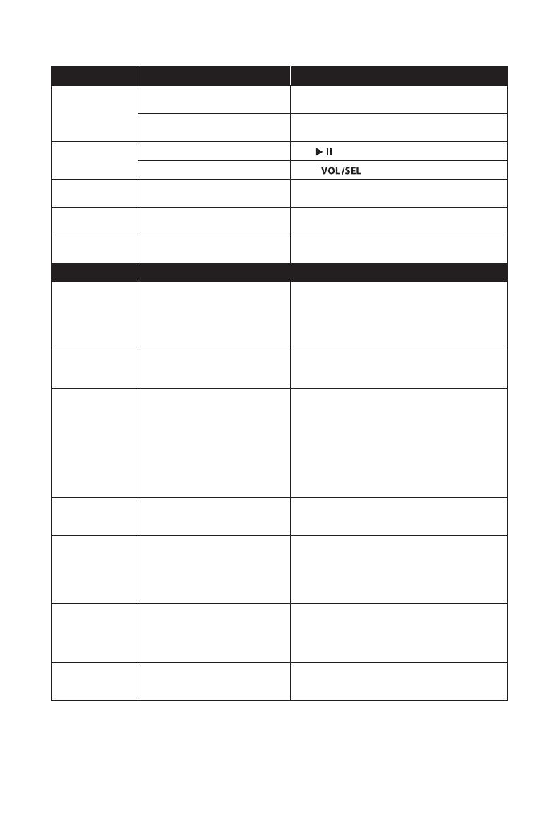
Problem Possible Cause Possible Solution
Unit doesn’t turn on
Faulty fuse
Remove fuse and check with continuity meter. Replace if
necessary.
Poor connection integrity
Check “Ground” and “+12VDC” connections for pinched
wires; ensure tight connections.
No or low sound
Mute is on
Press
to verify that Mute is not on.
Volume is turned down
Rotate
to adjust volume.
Amps not
turning on
Poor connection integrity
Check Amp Turn-On connections for pinched wires;
ensure tight connections.
No or poor
tuner reception
Poor connection integrity
Check antenna cable for pinched wires; ensure tight
connections.
USB connection not
working/charging
Poor connection integrity
Check USB cable for pinched wires; ensure tight connec-
tions.
SiriusXM
Check Antenna
A fault has been detected with the
SiriusXM antenna.
Ensure antenna cable is securely connected to the
SiriusXM Connect Vehicle Tuner.
Inspect the antenna cable for damage and kinks. Replace
the antenna if the cable is damaged. SiriusXM products
are available at your local audio retailer or online at www.
shop.siriusxm.com.
Check SXM Tuner
The radio is having diculty commu-
nicating with the SiriusXM Connect
Vehicle Tuner.
Verify the SiriusXM Connect Tuner cable is securely
connected to the radio.
No Signal
The SiriusXM Connect Tuner is having
diculty receiving the SiriusXM satellite
signal.
Verify that your vehicle is outdoors with a clear view of the
sky. Verify that the SiriusXM antenna is mounted securely
to the outside of the vessel.
Remove obstructions above or next to the SiriusXM
antenna. Inspect antenna cable for damage and kinks.
Consult the SiriusXM Connect Tuner installation manual
for more information on antenna installation. Replace the
antenna if the cable is damaged. SiriusXM products are
available at your local audio retailer or online at www.
shop.siriusxm.com.
Subscription
Updated
The radio has detected a change in your
SiriusXM subscription status. Press the
BACK button to clear the message.
Visit www.siriusxm.com or call 866-635-2349 in the USA or
877-438-9677 in Canada if you have questions about your
subscription.
Channel Not
Available
The channel that you have requested
is not a valid SiriusXM channel or the
channel is no longer available. You may
also see this message briey when rst
connecting a new SiriusXM Connect
Tuner.
Visit www.siriusxm.com for more information about the
SiriusXM channel lineup.
Channel Not Sub-
scribed
The channel that you have requested is
not included in your SiriusXM subscrip-
tion package or the channel that you
were listening to is no longer included
in your SiriusXM subscription package.
Visit www.siriusxm.com or call 866-635-2349 in the USA
or 877-438-9677 in Canada if you have questions about
your subscription package or would like to subscribe to
this channel.
Channel Locked
The channel that you have requested
is Locked by the radio Parental Control
feature.
See page 15 for more information on the Parental Control
feature and how to access locked channels.
Sirius XM Radio Inc. Sirius, XM and all related marks and logos are trademarks of Sirius XM Radio Inc.
The Bluetooth® word mark and logos are registered trademarks owned by Bluetooth SIG, Inc.
The aptX® word mark and logos are registered trademarks owned by CSR.
iPhone® and Lightning are registered trademarks of Apple Inc.
Use of all trademarks by JL Audio is under license.
19
Specifications
Electrical Specications
Operating Voltage 14.4V DC (10V – 15.9V allowable)
Maximum Current Draw 1.5 A
Standby Current Draw 120 mA
Fuse Value 5 A
Remote Turn-on Capacity 40 mA (max)
Operating Temp Range -4 F to +158 F (-20 C to +70 C)
Display
Size / Type 3.5-inch / TFT LCD backlighted
Resolution 320 x 240
Audio Outputs/Inputs
Output Channels 4 stereo pairs of RCA plugs (3 variable + 1 xed level)
Output Zones
1 main zone (variable), 2 assignable zones (variable)
and 1 xed level zone
Maximum Output Voltage 4V RMS (zones 1/2/3), selectable 4V/2V/1V RMS (zone 4)
Output Impedance 250 ohm
Input Channels 1 stereo pair of RCA plugs (2V/1V RMS input sensitivity)
Tuner
FM Tuner with RDS 87.5 MHz to 107.9 MHz (0.2 MHz step)
AM Tuner 530 kHz to 1710 kHz (10 kHz step)
NOAA Weather Band Tuner 162.400 MHz to 162.550 MHz (0.025 MHz step)
Favorites 18 presets across all tuners
Bluetooth®
Prole A2DP v1.2, AVRCP v1.4
Core Specication Version 2.1 + EDR
Codec SBC, aptX®
Connection Range Up to 35 ft / 11 m
USB
Interface USB 2.0 host
Maximum Current Output 1 A
Supported Audio Formats MP3, WAV, WMA
iPhone® Compatibility 5, 5c, 5s, 6, 6+, 6s, 6s+ (all Lightning connector models)
Dimensions
Unit W x H x D 5.94 in. x 3.90 in. x 3.17 in. (151 mm x 99 mm x 80.5 mm)
Mounting Hole W x H 4.70 in. x 3.25 in. (119.50 mm x 82.50 mm)
Limited Warranty – Electronics (USA)
JL Audio warrants this product to be free of defects in materials and workmanship
for a period of two (2) years from the original date of purchase.
This warranty is not transferable and applies only to the original purchaser from an
authorized JL Audio dealer. Should service be necessary under this warranty for any
reason due to manufacturing defect or malfunction, JL Audio will (at its discretion),
repair or replace the defective product with new or remanufactured product at no
charge. Damage caused by the following is not covered under warranty: accident,
misuse, abuse, product modification or neglect, failure to follow installation
instructions, unauthorized repair attempts, misrepresentations by the seller. This
warranty does not cover incidental or consequential damages and does not cover
the cost of removing or reinstalling the unit(s). Cosmetic damage due to accident or
normal wear and tear is not covered under warranty.
Warranty is void if the product’s serial number has been removed or defaced.
Any applicable implied warranties are limited in duration to the period of the express
warranty as provided herein beginning with the date of the original purchase at
retail, and no warranties, whether express or implied, shall apply to this product
thereafter. Some states do not allow limitations on implied warranties, therefore
these exclusions may not apply to you. This warranty gives you specific legal rights,
and you may also have other rights, which vary from state to state.
If you need service on your JL AUDIO product:
All warranty returns should be sent to JL Audio ’s Electronics Service Facility freight-
prepaid through an authorized JL Audio dealer and must be accompanied by proof
of purchase (a copy of the original sales receipt). Direct returns from consumers or
non-authorized dealers will be refused unless specifically authorized by JL Audio
with a valid return authorization number. Warranty expiration on products returned
without proof of purchase will be determined from the manufacturing date code.
Coverage may be invalidated as this date is previous to purchase date. Non-defective
items received will be returned freight-collect. Customer is responsible for shipping
charges and insurance in sending the product to JL Audio. Freight damage on returns
is not covered under warranty.
For Service Information in the U.S.A. please call
JL Audio Customer Service:
(954) 4 43 -1100
9:00 AM – 5:30 PM (Eastern Time Zone)
JL Audio, Inc.
10369 North Commerce Pkwy.
Miramar, FL 33025
(Do not send product for repair to this address)
International Warranties:
Products purchased outside the United States of America are covered only
by that country’s distributor and not by JL Audio, Inc.
MM100s-MAN-032116
  • Page 1 1
  • Page 2 2
  • Page 3 3
  • Page 4 4
  • Page 5 5
  • Page 6 6
  • Page 7 7
  • Page 8 8
  • Page 9 9
  • Page 10 10
  • Page 11 11
  • Page 12 12
  • Page 13 13
  • Page 14 14
  • Page 15 15
  • Page 16 16
  • Page 17 17
  • Page 18 18
  • Page 19 19
  • Page 20 20

JL Audio MediaMaster 100s Owner's manual

Category
Musical Equipment
Type
Owner's manual
This manual is also suitable for

Ask a question and I''ll find the answer in the document

Finding information in a document is now easier with AI