Liebherr MKUv 1613 Owner's manual

Type
Owner's manual

This manual is also suitable for

7085 861-00
Original operating instructions Page 14
Refrigerator
Read the operating instructions before switching on for the rst time
EN
MKUv 1610
MKUv 1613
14
Content
Priority of warnings .................................................................14
Safety instructions and warnings ...........................................14
Symbols on the appliance ...................................................... 15
Intended use ...........................................................................15
Foreseeable incorrect use......................................................15
Declaration of conformity .......................................................15
EPREL database .................................................................... 15
Noise emissions from the appliance ......................................16
Climate rating .........................................................................16
Description of the appliance ...................................................16
Setting up ...............................................................................16
Levelling the appliance ...........................................................16
Appliance dimensions ............................................................16
Electrical connection ..............................................................17
Energy consumption ............................................................. 17
Temperature increase after a power failure ............................17
Power failure alarm .................................................................17
Operating and control elements .............................................17
Interior temperature ................................................................17
Switching the appliance on and o ........................................ 18
Door open alarm .....................................................................18
Setting the delay time for the door open alarm ....................... 18
Audible warning signal settings .............................................. 18
Alarm test ...............................................................................18
Alarm messages ....................................................................19
Calling up stored alarm events and reading the
temperature progression ........................................................ 19
Resetting the stored alarm events HAn ..................................19
Resetting the recorded temperature progression rt .............. 19
Example of an alarm query ....................................................19
Keypad lock ............................................................................ 20
Setting the real time clock ......................................................20
Conversion from summer to winter time ................................. 20
Enabling/disabling automatic conversion from summer to
winter time ..............................................................................21
Changing the network address .............................................21
Resetting the parameters to factory settings .........................21
Safety lock ..............................................................................21
Interior light .............................................................................21
Defrosting ............................................................................... 21
Setting the display indication for the defrost phase ...............21
Activating the defrost function manually ................................21
Cleaning and disinfection ....................................................... 22
Disposal notes ........................................................................ 22
Shutting your appliance down ................................................22
Malfunctions ........................................................................... 23
Possible error messages in the display ..................................23
External alarm ........................................................................24
Installation dimensions (mm) ..................................................24
Changing over door hinges ....................................................25
Priority of warnings
DANGER
identies a situation involving direct
danger which, if not obviated, may result
in death or severe bodily injury.
WARNING
identies a dangerous situation which,
if not obviated, may result in death or
severe bodily injury.
CAUTION
identies a dangerous situation which,
if not obviated, may result in minor or
medium bodily injury.
NOTICE
identies a dangerous situation
which, if not obviated, may result in
damage to property.
Note
identies useful information and tips.
Safety instructions and warnings
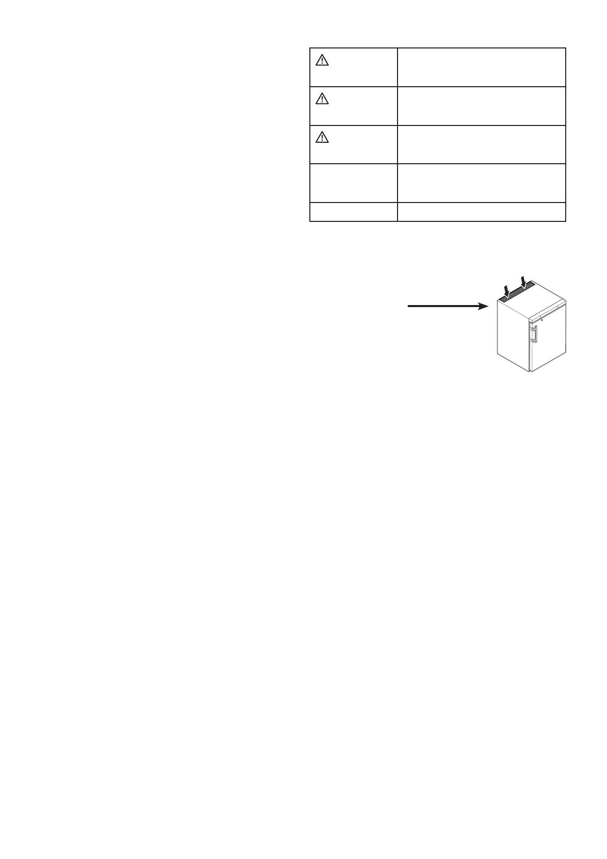
- WARNING: do not seal ventilation
openings on the appliance hous-
ing or enclosure.
- WARNING: only use the mechani-
cal devices or other aids recom-
mended by the manufacturer
to help speed up the defrosting
process.
- WARNING: do not damage the refrigerant circuit.
- WARNING: do not use any electrical devices in the
refrigerator compartment which do not comply with
the design recommended by the manufacturer.
- WARNING: the mains cable must not be dam-
aged while installing the appliance.
- WARNING: multi-sockets or distributor strips
and other electronic devices (such as halogen
transformers) must not be positioned and oper-
ated at the rear of appliances.
- WARNING: danger of injury through electric
shock. There are live parts under the cover. Only
have the interior LED light replaced or repaired
by customer service staff or trained personnel.
- WARNING: risk of injury from the LED lamp. The
light intensity of the LED light complies with laser
class RG 2. If the cover is defective, do not look
directly at the light through optical lenses from
close distance. This may damage your eyes.
- WARNING: this appliance must be secured as
described in the operating instructions to rule
out any potential risks due to its instability.
15
EN
- This appliance can be used by children of 8 years
old and over, and also by persons with restricted
physical, sensory or mental capacity or lack of
experience and knowledge, if they are supervised
or have been instructed on safe use of the appli-
ance and understand the resulting risks. Children
must not be allowed to play with the appliance.
Cleaning and user maintenance must not be
carried out by children without supervision.
- Do not store any explosive substances, such as
aerosol containers with flammable propellant
gas, inside the appliance.
- To prevent injury and damage to property, the
appliance should only be installed by two people.
- After unpacking it, check the appliance for signs
of damage. Contact the supplier if it is damaged.
Do not connect the appliance to the mains power
supply.
- Avoid prolonged skin contact with cold surfaces
(e.g. chilled/frozen products). If necessary, take
safety action (e.g. gloves).
- All repairs and work on the appliance may only
be carried out by customer service personnel
or other trained personnel. The same applies to
changing the mains power cable.
- Only carry out repair and other work on the ap-
pliance when the mains plug has visibly been
disconnected.
- Only install, connect and dispose of the appliance
as described in these operating instructions.
- When disconnecting the appliance from the
mains, pull on the plug. Do not pull on the cable.
- Do not use the interior LED light to light the room.
The interior LED light is only designed to illuminate
the interior of the appliance.
- Do not allow naked ames or ignition sources to
enter the appliance.
Symbols on the appliance
The symbol can be located on the compressor. It
refers to the oil in the compressor and indicates
the following danger: swallowing or inhaling can
be fatal. This is only relevant for recycling. There
is no danger in normal operation.
Warning about inammable substances.
A sticker to this eect may be applied to the rear
of the appliance. It refers to the foampadded
panels in the door and/or the housing. This is
only relevant for recycling. Do not remove the
sticker.
Declaration of conformity
The refrigerant circuit has been tested for leaks. The appliance
complies with the relevant safety regulations and EU Directives
2006/42/EG, 2014/30/EU, 2009/125/EG and 2011/65/EU.
Intended use
This pharmacy refrigerator for professional use is suitable for
storing products at a temperature of +5°C.
Typical products for storage include medication, drugs or other
pharmaceutical products which require refrigeration and must be
kept in a temperature range from +2°C to +8°C.
The appliance complies with DIN 58245 - Refrigerators for drugs.
For the storage of valuable or temperature-sensitive substances
or products the use of an independent, constantly monitoring
alarm system is necessary.
This alarm system must be designed so that each alarm status
is detected immediately by an authorised person who can then
take appropriate action.
Foreseeable incorrect use
Do not use the appliance for the following applications:
Storage and cooling of
- chemically unstable, inflammable or caustic substances
- blood, plasma or other bodily fluids for the purposes of infu-
sion, application or insertion into the human body.
Use in potentially explosive atmospheres.
Use outdoors or in areas where it is exposed to splash water or
damp conditions.
Incorrect use of the appliance will result in damaging or spoiling
the goods stored in it.
EPREL database
As from 1 March 2021, information about energy labelling and
ecodesign requirements will be available in the European product
database (EPREL). You can access the product database using
the following link: https://eprel.ec.europa.eu/. You will be asked
to enter the model identier. You will nd the model identier on
the type plate.
16
Levelling the appliance
Compensate oor unevenness using the
adjustable feet.
NOTICE
The appliance must be aligned horizontally
and vertically. If the appliance is not level, the
main body of the appliance can be deformed
and the door will not close properly.
Setting up
Do not place the appliance in direct sunlight or near radiators
and similar sources of heat.
Standard EN 378 specifies that the room in which you install
your appliance must have a volume of 1 m
3
per 8 g of R 600a
refrigerant used in the appliance, so as to avoid the formation of
inflammable gas/air mixtures in the room where the appliance is
located in the event of a leak in the refrigerant circuit. The quantity
of refrigerant used in your appliance is indicated on the type plate
on the inside of the appliance.
Always install the appliance directly against the wall.
Climate rating
The climate rating indicates at what
room temperature the appliance
may be operated to achieve full cool-
ing capacity and what the maximum
humidity level in the area around the
appliance may be to ensure that no
condensation forms on the exterior
housing.
The climate rating is indicated on the type plate.
Climate rating
Max. room
temperature
Max. relative
humidity
3 25 °C 60%
4 30 °C 55%
5 40 °C 40%
7 35 °C 75%
The minimum room temperature at the place of installation is 10°C.
Description of the appliance
(1) Operating and control elements
(2) Interior light (LED light strip) (MKUv 1613)
(3) Type plate
(4) Drawers
(5) Reference sensor
(6) Adjustable-height feet
NOTICE
The maximum load per drawer shelf is 25 kg.
Noise emissions from the appliance
The noise level while the appliance is operating is below 70 dB(A)
(relative noise level 1 pW).
Other features
- Audible and visual temperature alarm.
- Audible and visual door open alarm.
- Floating contact for connection to a remote monitoring system.
- Serial interface (RS485) for external temperature and alarm
documentation.
- Maximum/minimum interior temperatures are stored.
- Last 3 temperature alarms are saved with time, date and duration
of alarm.
- Last 3 power cuts are saved with time, date and duration of power
cut.
- Safety thermostat to avoid temperatures below +2°C.
It is essential to use these safety facilities to avoid damage
to stored items. These facilities must not be deactivated or
decommissioned!
Appliance dimensions
17
EN
Operating and control elements
On/O button (switching the appliance on and off)
Selection buttons
Defrost button (for manually activating the defrost function)
Keypad lock
Button for calling up stored alarm events
Audible alarm O button
Enter button
Symbols in the display
Compressor is running
LED ashing - refrigeration unit switches on after a delay.
The compressor will start automatically after the pressure
in the refrigerant circuit has equalised.
Fan is running
Appliance is defrosting
Temperature display via reference sensor is activated
LED flashing and appears in the display. The real
time clock must be reset.
The display means that the power supply and interior
temperature of the appliance are recorded.
If ashes in the display, there has either been a power
failure or the temperature in the appliance exceeded the
permissible range.
Alarm function
The appliance has suffered a fault. Contact the customer
service department.
Electrical connection
Only operate the appliance with alternating current (AC).
The permissible voltage and frequency are indicated on the type
plate. The position of the type plate is shown in the section entitled
Description of the appliance.
The socket must be properly earthed and protected by a fuse.
The tripping current of the fuse must be between 10 A and 16 A.
The socket must not be situated behind the appli-
ance and must be easily accessible.
Do not connect the appliance using an exten-
sion cable or extension socket.
Do not use stand-alone inverters (conversion
of direct current to alternating/three-phase
current) or energy-saving plugs. Risk of dam-
age to the electronic control system!
Connect the appliance to the mains - the display reads OFF.
Note
It will take 24 hours for the batteries in the power failure alarm to
become fully charged.
Instructions for decommissioning the appliance
When decommissioning the appliance, it is essential to follow
the instructions in the section entitled "Shutting your appli-
ance down".
Otherwise, the power failure alarm will be activated when the
mains plug is disconnected.
Energy consumption
Temperature increase after a power failure
Model MKUv 1610 MKUv 1613
Energy consumption pursu-
ant to ÖNORM K 2040 and
DIN 58345
0.5 kWh/24h 0.8 kWh/24h
Temperature increase after a
power failure from +5°C to +8°C
pursuant to ÖNORM K 2040
40 minutes 40 minutes
Temperature increase after
a power failure from +5°C to
+10°C pursuant to DIN 58345
60 minutes 40 minutes
Power failure alarm
In the case of a power failure, the audible warning signal will sound
and
will be shown in the display.
If
appears in the refrigerator’s display, the temperature has
risen above the upper alarm limit of + 8°C.
Check the temperature progression as described in the section
entitled
Calling up stored alarm events
and then make a decision on what you wish to do with the items
stored in the refrigerator.
Interior temperature
The temperature inside the appliance is set to +5°C (+/-3K) as
required by DIN 58345 and cannot be changed.
NOTICE
Items must not be stored in the appliance until the
temperature has reached 5°C.
Note
The temperature in the warmest area of the interior may be higher
than the temperature setting.
If the door is left open for a lengthy period, the temperature in the
appliance's compartments may rise dramatically.
18
Alarm test
This test checks the function of the internal and any external
connected alarm device.
The appliance does not stop its refrigerating function during this
test.
Press
+ for 5 seconds.
The display will change to a temperature value of 0.2°C below
the set upper alarm limit.
The temperature value will now rise by 0.1°C every 2 seconds.
When the upper alarm limit is reached,
will appear in the
display. An external alarm unit connected to the floating alarm
output will now be activated.
The temperature value will continue to rise up to 0.2°C above
the upper alarm limit.
The same process will take place automatically for the lower
alarm limit.
will appear in the display.
The LED will be lit during the test.
The electronic control system will switch back to normal operat-
ing mode.
Cancelling the test prematurely
Press
for 5 seconds.
Audible warning signal settings
The audible warning signal will be muted for the current alarm after
the button
has been pressed. Complete the following steps if
you want the audible warning signal to reactivate automatically.
Press
for 5 seconds. Display =
Press until appears in the display.
Press
. Display =
Press
. Display =
Press
. Display =
Automatic reactivation of the audible warning signal is now active.
The time before the audible warning signal sounds again must be set.
Press
. Display =
Press . Display = Setting range = 1 - 120 minutes.
Use button
or to select the desired setting.
Press
. Display =
Press for 5 seconds.
The electronic control system will switch back to normal operat-
ing mode.
Setting the delay time for the door open alarm
The time before the audible warning signal sounds after the door
has been opened can be adjusted.
Press
for 5 seconds. Display =
Press until appears in the display.
Press
. Display = Setting range = 1 - 5 minutes.
Use button
or to select the desired setting.
Press
. Display =
Press
for 5 seconds.
The electronic control system will switch back to normal operat-
ing mode.
Door open alarm
When the door is opened, the LED lights up and the temperature
display begins to ash.
When the door has been left open for more than 60 seconds, the
LED
begins to ash, and and the temperature indication
ash alternately in the display.
The audible warning signal sounds.
If the door has to stay open for longer in order to insert items to be
cooled, cancel the audible warning signal by pressing button
.
Switching the appliance on and o
Connect the appliance to the mains. Display = OFF.
Switching the appliance on
Press for approx. 5 seconds. Display = ON.
No alarm is displayed or sounded when the appliance is switched
on for the rst time.
If the appliance is disconnected from the mains for a long time after
it has been switched on for the rst time and if the temperature
inside the appliance rises above the upper alarm limit, this will be
detected as a fault by the electronic control system (
ashes
in the display).
When the appliance is switched on again, this display must be
reset as shown below.
Press
.
Press
+ for 5 seconds. Display =
The LED will now light up permanently.
Press
for 5 seconds.
The electronic control system will switch back to normal operat-
ing mode.
Switching the appliance o
Press for approx. 5 seconds. Display =
19
EN
Resetting the recorded temperature progres-
sion rt
Press
. Display =
Press the button or until appears in the display.
Press
. Display = -
Press for 5 seconds. Display = .
The values for
and (highest and lowest measured interior
temperature) are then reset to the current interior temperature.
Press
for 5 seconds. The electronic control system will switch
back to normal operating mode.
Resetting the stored alarm events HAn
Press . Display =
Press + for 5 seconds. Display = .
Press
for 5 seconds.
The electronic control system will switch back to normal operat-
ing mode.
Example of an alarm query
Situation: HA/HF/ ashes in the display.
Press
. Display=
Press . Display =
There has not been an alarm status with a too high or too low
temperature. You must switch to display
.
Press
. Display =
Press until appears in the display.
Press
. Display = 1 power failure has occurred.
Press
. Display =
Press . Display =
Last power failure.
Press
. Display = (year)
Press
. Display = (month 1-12)
Press
. Display = (day 1-31)
Press
. Display = (hour 0-23)
Press
. Display = (minute 0-59)
Press
. Display = (period of time in minutes)
Press
+ for 5 seconds. Display =
The LED will now light up permanently.
HA/HF is cancelled in the display.
The electronic control system is now ready for the next alarm.
Press
for 5 seconds. The electronic control system will switch
back to normal operating mode.
Calling up stored alarm events and reading
the temperature progression
Press . Display =
Scroll through the list using or .
Number of temperature alarms
Last temperature alarm
Last temperature alarm but one
Temperature alarm before
Number of power cuts
Last power cut
Last power cut but one
Power cut before
Period in hours in which the maximum and minimum interior
temperatures were measured
Maximum (highest) measured temperature
Lowest measured temperature
Select the required item using the
button. Press this button
again to return to the list.
You can exit the menu at any time by pressing
for 5 seconds.
If no button is pressed within 60 seconds, the electronic control
system switches back automatically.
Alarm messages
1. LED ashes in the display
If
appears in the display, the appliance has a fault. Consult
your nearest customer service point.
2. LED
ashes in the display; the display reads HI or LO
The interior is too warm (HI) or too cold (LO). The audible warn-
ing signal sounds.
Note
The alarm parameters can be adjusted. See Adjusting the
alarm parameters.
3. HA / HF /
flashes in the display
There has been a power cut (HF) of some length or the interior
was too warm or too cold (HA) during a certain period of time.
Up to three alarm events can be stored and called up.
4. LED
ashes in the display; the display reads AFr
The temperature near the reference sensor was too low for a
certain period of time.
Cancel the alarm status AFr.
Press
+ for 5 seconds.
If the message reappears several hours after this cancellation,
refer to the instructions in the section entitled "Malfunctions".
20
Setting the real time clock
The real time clock is preset (CET). For a dierent time zone, the
time must be adjusted manuall.
Press
for 5 seconds. Display =
Press . Display =
Press
. Display = (year)
Press
. Display =
Set the year by pressing the
buttons. Press .
Press
. Display = (month 1-12)
Press
. Display =
Set the month by pressing the
buttons. Press .
Press
. Display = (day 1-31)
Press
. Display =
Set the day by pressing the
buttons. Press .
Press
. Display = (days of the week)
(1 = Monday, 7 = Sunday)
Press
. Display =
Set the day of the week by pressing the
buttons. Press .
Press
. Display = (hour 0-23)
Press
. Display =
Set the hour by pressing the
buttons. Press .
Press
. Display = (minute 0-59)
Press
. Display =
Set the minutes by pressing the
buttons. Press .
Press
for 5 seconds.
The electronic control system will switch back to normal operat-
ing mode.
When
appears in the display, the real time clock must be
reset.
Keypad lock
The keypad lock ensures that no unintentional changes are made
to the electronic control system.
Setting a PIN code for the keypad lock function
Press for 5 seconds. Display =
Press until appears in the display.
Press
. Display =
Use button or to choose a PIN code between 1 and 999.
Press
. Display =
Press for 5 seconds.
The electronic control system will switch back to normal operat-
ing mode.
Activating the keypad lock
Press for 5 seconds. Display =
Use button or to select the PIN code.
Press
. Display =
All buttons except and are locked.
If an incorrect PIN code is entered, the electronic control system
switches back to normal operation without activating the keypad
lock.
Deactivating the keypad lock
Press for 5 seconds. Display =
Use button or to select the PIN code.
Press
. Display =
All functions are enabled.
If an incorrect PIN code is entered, the keypad lock remains active.
Conversion from summer to winter time
Conversion to summer time is carried out automatically by the
electronic control system on the last Sunday in March at 2 o’clock
in the morning.
Conversion to winter time is carried out automatically by the elec-
tronic control system on the last Sunday in October at 2 o’clock
in the morning.
In order to enable the new time, the appliance must be switched
o and on after each of the times specied above.
21
EN
Setting the display indication for the defrost
phase
Press for 5 seconds. Display =
Press . Display =
Use button or to select the desired setting.
0 = Symbol
+ alternating display of and the current tem-
perature in the interior of the appliance.
1 = Symbol
+ temperature before the start of the defrost phase.
2 = Symbol
+ .
Press
. Display =
Press for 5 seconds. The electronic control system will switch
back to normal operating mode.
Safety lock
The lock in the appliance door is
equipped with a safety mecha-
nism.
Locking the appliance
• Insert the key as shown by ar-
row 1.
Turn the key 90°.
To unlock the appliance, the same procedure must be repeated
in the same order.
Activating the defrost function manually
If the door has been left slightly open for a long time, a layer of
ice may form in the interior and on the cooling plate. The defrost
function can then be activated manually.
Press
for 3 seconds. Display = +
The electronic control system will automatically switch back to
normal operating mode.
Display =
Changing the network address
When connecting several appliances via the RS485 interface,
each appliance must have its own network address.
Press
for 5 seconds. Display =
Press until appears in the display.
Press
. Display =
Use button or to change the network address (1-207).
Press
. Display =
Press for 5 seconds.
The electronic control system will switch back to normal operat-
ing mode.
Enabling/disabling automatic conversion from
summer to winter time
Press for 5 seconds. Display =
Press until appears in the display.
Press
. Display =
Use button or to select the desired setting.
0 = deactivated 1 = activated
Press
. Display =
Press for 5 seconds.
The electronic control system will switch back to normal operat-
ing mode.
Switch on switch, the interior light
comes on.
Interior light
(LED light strip)
Defrosting
The appliance defrosts automatically.
Resetting the parameters to factory settings
The alarm limits and sensor calibration values can be reset to the
factory settings using this function.
Press
for 5 seconds. Display = OFF.
Press
+ for 5 seconds..
Display =
.
Wait 10 seconds!
Remove the plug. The display will be switched o.
Keep
pressed and connect the mains plug.
Display =
Press . Display =
The electronic control system will switch back to normal operat-
ing mode.
22
Cleaning and disinfection
WARNING
Before cleaning, always disconnect the appliance
from the mains. Pull out the plug or switch o the
fuse.
CAUTION
Risk of damage to the appliance components and
risk of injury due to hot steam.
Do not use steam cleaning equipment to clean
the appliance.
NOTICE
All surfaces in the appliance must be cleaned at
regular intervals!
Only disinfect the appliance with ethyl alcohol-based products.
• First clean the soiled areas and grid shelves with a damp cotton
cloth.
Clean the interior container, grid shelves and outer walls with
lukewarm water, ethyl alcohol-based cleaning products or water-
based household cleaning products.
Do not use chemical solvents or any cleaning agents containing
sand or acid.
To avoid short-circuits, ensure no cleaning water penetrates into
the electrical components when cleaning the appliance.
Dry all parts well with a cloth.
• The dust should be removed from the refrigeration unit and heat
exchanger - metal grid at the back of the appliance - once a year.
Do not damage or remove the type plate on the inside of the
appliance. It is very important for servicing purposes.
The appliance’s materials are only resistant to the cleaning
products listed above.
Regular cleaning and disinfection prevents severe soiling.
Disposal notes
The appliance contains reusable materials and should
be disposed of properly - not simply with unsorted
household refuse. Appliances which are no longer
needed must be disposed of in a professional and
appropriate way, in accordance with the current local
regulations and laws.
Do not damage the refrigerant circuit of an appliance that is no
longer needed during its disposal.
This appliance contains inammable gases in the refrigerant
circuit and insulation foam.
Your local council or a waste disposal contractor can provide
information about how to dispose of the appliance correctly.
A rechargeable battery is installed in the appliance.
Disposal instructions for batteries
The battery must be removed when you wish to dispose of the
appliance and sent for separate waste treatment for batteries.
Do not damage or short circuit the battery.
Shutting your appliance down
If the appliance is left empty for a lengthy period, it must be
switched o, defrosted, cleaned and dried and the door is to be
left open to prevent mould formation.
If the appliance is to be left switched o for any length of time,
complete the following steps to disconnect the power failure
alarm battery from the electronic control system.
Press
for 5 seconds. Display = OFF.
Press
+ for 5 seconds..
Display =
.
Wait 10 seconds!
Remove the plug.
The display will be switched o.
Note
If the display is not switched off,
press the button on the power sup-
ply unit.
23
EN
Malfunctions
You may be able to rectify the following faults by checking
the possible causes yourself:
Appliance does not function:
Is the appliance switched on?
Is the plug correctly fitted in the mains socket?
Is the fuse intact?
The temperature is not low enough:
Is the ventilation system working properly?
Is the appliance set up too close to a heat source?
The display temperature is significantly lower than the set
temperature. Check the following:
- Are the items located too close to the reference sensor?
The distance between the items and the reference sensor
housing must be at least 5 cm.
- Are the grid shelves fully covered with cartons or drawers?
This would prevent air circulation inside the appliance and result in
a much colder temperature value being measured and displayed.
Contact the customer service department if the displayed tem-
perature is signicantly lower for more than 1 day to ask about
information for an individual adjustment.
If none of the above causes
apply and you cannot rec-
tify the fault yourself, contact
the nearest customer ser-
vice department stating the
type designation
1, service
number
2and appliance
number
3as indicated on the
type plate.
The position of the type plate is shown in the section entitled
Description of the appliance.
Possible error messages in the display
Error
code
Error Action
E0, E1,
E2, rE
Temperature sensor
defective
Contact the customer
service department
EE, EF Electronic control
system error
Contact the customer
service department
dOr Appliance door
open for too long
Close appliance door
HI Temperature inside
appliance too high
(too warm)
Check that the door has
been closed properly. If
the temperature does not
drop, contact the customer
service department.
LO Temperature inside
appliance too low
(too cold)
Contact the customer
service department
Etc Reset the real time clock (see
"Setting the real time clock")
HF, HA There has been a
power cut of some
length or the interior
was too warm or too
cold during a certain
period of time.
See
Calling up stored alarm
events and reading the
temperature progression
AFr Temperature around
the reference sensor
< 0°C
Cancel the message - see
"Alarm messages".
Contact the customer
service department if the
message reappears on a
regular basis.
btE Back-up Battery error Check if the battery is
connected properly. See
Back-up Battery. If the
connection is correct
and the error code is
still displayed, contact
the customer service
department.
btP Power failure alarm It will go out again when
mains voltage is applied.
Make a decision on what
you wish to do with the
items stored in the appli-
ance.
24
Terminating resistor
When connecting several appliances via
the RS485 interface, the terminating re-
sistor must remain on the last appliance.
Remove the terminating resistors
from the appliances in between.
External alarm
There are various connection options at
the back of the appliance.
The appliance may only be connected
to an external alarm device by trained
personnel.
Floating alarm output
Connection to
RS485 interface
Note
The connectors are secured with
screws. To remove the connectors,
undo the left and right screws.
RS485 interface
Rx- / Tx-
Send/Receive data cable
(negative pole)
Rx+ / Tx+ Send/Receive data cable
(positive pole)
GND Earth cable
N.O
Connection for a visual warning light or an
acoustic alarm signal.
N.C
Connection for a control lamp to indicate that
the appliance is in normal mode.
COM
External power supply unit, 42 V/8 A DC maximum, Minimum
current: 150 mA
Floating alarm output
These three contacts can be used to connect the appliance to
an optical or acoustic alarm device. The connection is designed
for a maximum of 42 V/8 A DC from a safety extra-low voltage
(SELV) source (minimum current: 150 mA).
Notice
When supplying mains voltage to the oating alarm contact,
the technical safety requirements of standard EN 60335
will not be satised.
Installation dimensions (mm)
Version 1
A cross-section of min. 200 cm
2
is re quired in the
worktop for ventilation of the rear of the appliance.
Version 2
If no ventilation grille is provided in the worktop, the recess
must be at least 860 mm high to ensure adequate heat
dissipation to the front.
25
EN
Changing over door hinges
1. Unscrew the hinge bracket.
Note
The door mounting has a spring
mechanism enabling the door to
close by itself. The hinge bracket
turns to the left when the screws
are undone.
2. Pull the door out at the bottom
and lift o.
3. Transfer plugs to the other side.
4. Transfer pin on hinge bracket to the opposite side.
5. Transfer upper hinge
components to the op-
posite side.
6. Transfer covers to the opposite side.
7. Mount door on hinge pin and
close.
8. Insert hinge bracket in lower
door mounting. Turn hinge
bracket by 90° - spring is
compressed. Screw on hinge
bracket.
4
5
6
7
8
3
9. Screw on the handle.
10. Push on pressure plates
until they engage.
9
10
*708586100*
Liebherr-Hausgeräte GmbH
Memminger Straße 77-79
88416 Ochsenhausen
Germany
home.liebherr.com
  • Page 1 1
  • Page 2 2
  • Page 3 3
  • Page 4 4
  • Page 5 5
  • Page 6 6
  • Page 7 7
  • Page 8 8
  • Page 9 9
  • Page 10 10
  • Page 11 11
  • Page 12 12
  • Page 13 13
  • Page 14 14
  • Page 15 15
  • Page 16 16

Liebherr MKUv 1613 Owner's manual

Type
Owner's manual
This manual is also suitable for

Ask a question and I''ll find the answer in the document

Finding information in a document is now easier with AI