Billy Goat FM3300 User manual

Category
Garden tools
Type
User manual

This manual is also suitable for

Part No. 520141 Form No. F061604A
33" TRIPLE BLADE MOWER
COMMERCIAL
Page 1 of 20
Operator Owner's Manual
Thank You for Selecting
1
3
Specifi cations
The Powerful Self-Propelled Billy Goat Mower
UNIT SIZE: OVERALL LENGTH - 57"(1.44 m)
OVERALL WIDTH - 43" (1.09 m)
OVERALL HEIGHT - 47" (1.19 m)
FM3300 & FM3300E
FM3300 FM3300E
Engine: HP 13.0 HP (9.7 kW) 13.0 HP (9.7 kW)
Engine:Type B&S INTEK OHV B&S INTEK OHV
ELECTRIC START
Engine: Fuel cap. 3.0 qt. (2.8 L) 3.0 qt. (2.8 L)
Engine: Oil Cap. 1.5 qt. (1.4 L) 1.5 qt. (1.4 L)
Weight: Unit 267 # (121 Kg) 277 # (126 Kg)
Weight: Shipping 410 # (186 Kq) 420 # (191 Kq)
2
Accessories
Mulching Kit
P/N 520144
Reduces lawn clippings to fi ne nutrient-rich par-
ticles that fi lter down to the soil.
Grass Catcher Kit
P/N 520142
Easily convert your mower to bag grass and leaves.
Transaxle Guard Kit
P/N 520155
To protect the transaxle from accidental contact
from concrete curbs or other hazards.
Not for Reproduction
Part No. 520141 Form No. F061604A
because contact may cause burns.
22. DO NOT run engine without air cleaner
or air cleaner cover.
23. DO NOT operate during excessive vibra-
tion!
24. DO NOT leave machine unattended while
in operation.
25. DO NOT park machine on a steep grade
or slope.
WARNING: DO
1. ALWAYS DO remove the wire from the
spark plug when servicing the engine or
equipment TO PREVENT ACCIDENTAL
STARTING.
2. DO keep cylinder ns and governor parts
free of grass and other debris which can
affect engine speed.
3. DO pull starter cord slowly until resistance
is felt. Then pull cord rapidly to avoid kickback
and prevent hand or arm injury.
4. DO examine muf er periodically to be sure
it is functioning effectively. A worn or leaking
muf er should be repaired or replaced as
necessary.
5. DO use fresh gasoline. Stale fuel can gum
carburetor and cause leakage.
6. DO check fuel lines and ttings frequently
for cracks or leaks. Replace if necessary
7. Follow engine manufacturer operating and
maintenance instructions.
8. Inspect machine and work area before
starting unit.
SAFETY INSTRUCTIONS
GENERAL SAFETY
ASSEMBLY
LIT. BAG & CONTROLS
LABELS
OPERATION
MAINTENANCE
PARTS DRAWING & LIST
ACCESSORIES
TROUBLESHOOTING
WARRANTY PROCEDURE
WARNING: DO NOT
1. DO NOT run engine in an enclosed area.
Exhaust gases contain carbon monoxide, an
odorless and deadly poison.
2. DO NOT place hands or feet near moving
or rotating parts.
3. DO NOT store, spill or use gasoline near
an open ame, or devices such as a stove,
furnace, or water heater which use a pilot light
or devices which can create a spark.
4. DO NOT refuel indoors where area is not
well ventilated. Outdoor refueling is recom-
mended.
5. DO NOT fill fuel tank while engine is
running. Allow engine to cool for 2 minutes
before refueling. Store fuel in approved safety
containers.
6. DO NOT remove fuel tank cap while engine
is running.
7. DO NOT operate engine when smell of
gasoline is present or other explosive condi-
tions exist.
8. DO NOT operate engine if gasoline is spilled.
Move machine away from the spill and avoid
creating any ignition until the gasoline has
evaporated.
9. DO NOT transport unit with fuel in tank.
10. DO NOT smoke when lling fuel tank.
11. DO NOT choke carburetor to stop engine.
Whenever possible, gradually reduce engine
speed before stopping.
Page 2 of 20
TABLE OF CONTENTS
10 - 14
20
20
15 - 18
5 - 6
5
4
3
2
VIBRATION
VIBRATION LEVEL 2.65 g
Vibration levels at the operators handles were mea-
sured in the vertical, lateral, and longitudinal directions
using calibrated vibration test equipment. Tests were
performed on 08/19/03 under the conditions listed:
Sound tests were performed on 8/15/2003 under the conditions
listed:
6
8
THIS SYMBOL MEANS WARNING OR CAUTION. DEATH, PERSONAL INJURY AND/OR PROPERTY
DAMAGE MAY OCCUR UNLESS INSTRUCTIONS ARE FOLLOWED CAREFULLY.
BEFORE STARTING ENGINE, READ AND UNDERSTAND THE ENTIRE OPERATOR'S MANUAL &
ENGINE MANUAL.
12. DO NOT run engine at excessive speeds.
This may result in injury & /or damage to unit.
13. DO NOT tamper with governor springs,
governor links or other parts which may change
the governed engine speed.
14. DO NOT tamper with the engine speed
selected by the engine manufacturer.
15. DO NOT check for spark with spark plug
or spark plug wire removed. Use an approved
tester.
16. DO NOT crank engine with spark plug
removed. If engine is ooded, place throttle in
FAST position and crank until engine starts.
17. DO NOT strike ywheel with a hard object
or metal tool as this may cause flywheel to
shatter in operation. Use proper tools to service
engine.
18. DO NOT operate engine without a muf er.
Inspect periodically and replace, if necessary.
If engine is equipped with muffler deflector,
inspect periodically and replace, if necessary,
with correct de ector.
19. DO NOT operate engine with an accumula-
tion of grass, leaves, dirt or other combustible
material in the muf er area.
20. DO NOT use this engine on any forest
covered, brush covered, or grass covered
unimproved land unless a spark arrester is
installed on the muf er. The arrester must be
maintained in effective working order by the
operator. In the State of California the above is
required by law (Section 4442 of the California
Public Resources Code). Other states may
have similar laws. Federal laws apply on federal
lands.
21. DO NOT touch hot muf er, cylinder, or ns
5
IN THE INTEREST OF SAFETY
WARNING: The Engine Exhaust from this product contains chemicals known
to the State of California to cause cancer, birth defects or other reproductive harm.
6 - 9
SOUND
7
WIND SPEED:
WIND DIRECTION:
HUMIDITY:
TEMPERATURE:
BAROMETRIC PRESSURE:
GENERAL CONDITION:
29.9" Hg (759mm Hg)
37%
South East
5.5 MPH (8.9 kmh)
Sunny
99 °F (37.2 °C)
NOTE: Sound power level listed is the highest value for any model in this manual.
Please refer to serial plate on the unit for the sound level
for your model.
SOUND LEVEL 94.8 dBA at operator position
19
WIND SPEED:
WIND DIRECTION:
HUMIDITY:
TEMPERATURE:
BAROMETRIC PRESSURE:
GENERAL CONDITION:
30.2" Hg (767mm Hg)
57%
South
2.4 MPH (3.9 KPH)
Sunny
86 °F (30.0 °C)
Not for Reproduction
Part No. 520141 Form No. F061604A
Page 3 of 20
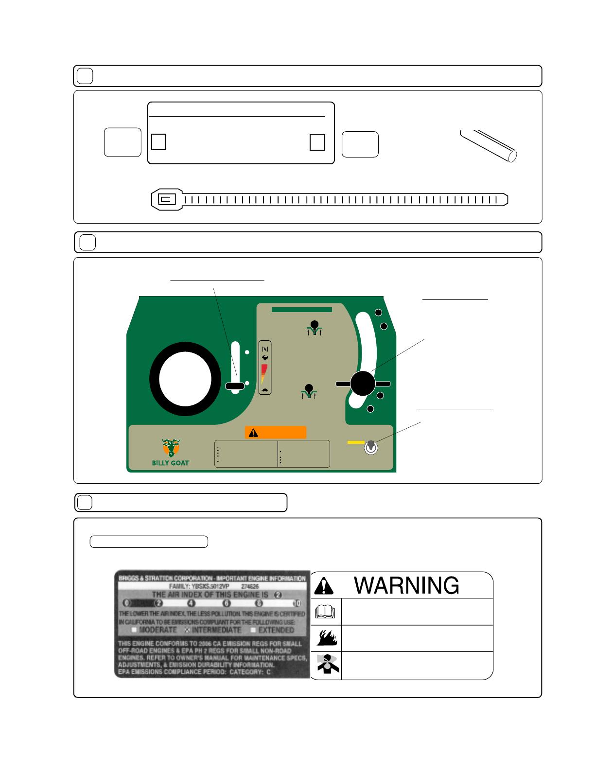
For your safety and the safety of others, these directions should be followed:
Do not operate this machine without fi rst reading
owner's manual and engine manufacturer's manual.
Use of Eye and Breathing protection is recom-
mended when using this machine.
GENERAL SAFETY
9
Use of Ear Protection is recommended while
operating this machine.
This cutting machine is capable of amputating hands and feet and
throwing objects. Failure to observe the following safety instructions
could result in serious injury or death.
I. General Operation
1. Read, understand, and follow all instructions on the machine and
in the manual(s). Be thoroughly familiar with the controls and the
proper use of the mower before starting.
2. Do not put hands or feet near or under rotating parts. Keep clear
of the discharge opening at all times.
3. Only allow responsible individuals, who are familiar with the
instructions, to operate the mower.
4. Clear the area of objects such as rocks, toys, wire, bones, sticks
etc., which could be picked up and thrown by the blade(s).
5. Be sure the area is clear of other people before mowing. Stop
mower if anyone enters the area.
6. Do not operate the mower when barefoot or wearing open
sandals. Always wear substantial foot wear.
7. Do not pull mower backwards unless absolutely necessary. Look
down and behind before and while moving backwards.
8. Do not operate the mower without proper guards, plates, grass
catcher or other safety protective devices in place.
9. See manufacturer’s instructions for proper operation and
installation of accessories. Only use accessories approved by
the manufacturer.
10. Stop the blade(s) when crossing gravel drives, walks, or roads.
11. Stop the engine (motor) whenever you leave the equipment,
before cleaning the mower or unclogging the chute.
12. Shut the engine (motor) off and wait until the blade comes to
complete stop before removing grass catcher.
13. Mow only in daylight or good arti cial light.
14. Do not operate the mower while under the in uence of alcohol
or drugs.
15. Never operate mower in wet grass. Always be sure of your footing;
keep a rm hold on the handle and walk; never run.
16. Disengage the self-propelled mechanism or drive clutch on
mowers so equipped before starting the engine (motor).
17. If the equipment should start to vibrate abnormally, stop the
engine (motor) and check immediately for the cause. Vibration is
generally a warning of trouble.
18. Always wear safety goggles or safety glasses with side shields
when operating mower.
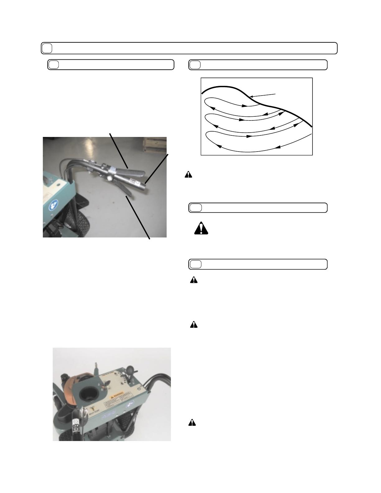
II. Slope Operation
Slopes are a major factor related to slip and fall accidents which can
result in severe injury. All slopes require extra caution. If you feel
uneasy on a slope, do not mow it.
DO:
Mow across the face of slopes; never up and down. Exercise extreme
caution when changing direction on slopes.
Remove objects such as rocks, tree limbs, etc. Watch
for holes, ruts, or bumps. Tall grass can hide obstacles.
DO NOT:
Do not mow near drop-offs, ditches, or embankments. The opera-
tor could lose footing or balance.
Do not mow excessively steep slopes.
Do not mow on wet grass. Reduced footing could cause slipping.
III. Children
Tragic accidents can occur if the operator is not alert to the
presence of children. Children are often attracted to the mower
and the mowing activity. Never assume that children will remain
where you last saw them.
1. Keep children out of the mowing area and under the watchful
care of a responsible adult.
2. Be alert and turn mower off if children enter the area.
3. Before and while moving backwards, look behind and down
for small children.
4. Never allow children to operate the mower.
5. Use extra care when approaching blind comers, shrubs, trees,
or other objects that may obscure vision.
IV. Service
1. Use extra care in handling gasoline and other fuels. They are
ammable and vapors are explosive.
a)Use only an approved container.
b)Never remove gas cap or add fuel with the engine running.
Allow engine to cool before refueling. Do not smoke.
c)Never refuel the machine indoors.
d)Never store the machine or fuel container inside where there
is an open ame, such as a water heater.
2. Never run an engine inside a closed area.
3.Never make adjustments or repairs with the engine (motor)
running. Disconnect the spark plug wire, and keep the wire away
from the plug to prevent accidental starting.
4. Keep all nuts and bolts, especially blade attachment bolts, tight
and keep equipment in good condition.
5. Never tamper with safety devices. Check their proper operation
regularly.
6. Keep mower free of grass, leaves, or other debris build-up.
Clean up oil or fuel spillage. Allow mower to cool before storing.
7. Stop and inspect the equipment if you strike an Object. Repair,
if necessary, before restarting.
8. Never attempt to make wheel height adjustments while the
engine (motor) is running.
9. Always disconnect electric mowers (live operated) before
cleaning, repairing, or adjusting.
10. Grass catcher components are subject to wear, damage, and
deterioration, which could expose moving parts or allow objects
to be thrown. Frequently check components and replace with
manufacturer’s recommended parts, when necessary.”
11. Mower blades are sharp and can cut. Wrap the blade(s) or
wear gloves, and use extra caution when servicing them.
12. Do not change the engine governor setting or overspeed
the engine.
Not for Reproduction
Part No. 520141 Form No. F061604A
11
ASSEMBLY
..
..
PUT OIL IN ENGINE BEFORE STARTING.
Read all safety and operating instructions
before assembling or starting this unit.
Your Billy Goat Mower is shipped from the factory
in one crate, completely assembled except for the
handles and console assembly.
DISCONNECT SPARK PLUG WIRE
BEFORE ASSEMBLING UNIT.
Page 4 of 20
8. Insert one of the handle mounting bolts (Item 102) with Hex. lock washer
(Item 6) through the rear handle mounting hole of the right side handle,
and screw it into the rear handle mounting hole on the right side of engine
base chassis (Item 61). Repeat this
procedure for the left side using the
left handle.
9.On each side of the mower, insert
one of the handle mounting bolts
(Item 102) with Hex. lock washer
(Item 6) through the hole in one
end of the handle brace (Item 32),
the front handle mounting hole of
the handle and screw into the front
handle mounting hole in the engine
base chassis (Figure 11-5).
10.Using one of the bolts and at
washers removed previously (step
8), insert the bolt with washer, from
the outside, through the bottom hole
on the console, through the handle,
through the top hole of the handle
brace, through one of the at wash-
ers removed in step 8 and secure
with lock nut (Item 151). Repeat this
procedure for the bottom hole on
the other side of the console. Make
sure control cables are free and not
damaged while tightening console
mounting bolts (Figure 6).
11.On the left hand side, using
one of the bolts and at washers
removed previously (step 6), insert
the bolt with washer, from the
outside, through the top hole on
the console, through the handle,
through the control cable retainer,
through one of the at washers
removed in step 8 and secure with
lock nut (Item 151). Repeat for right-
hand side except there is no control
cable retainer for this side. Make
sure the control cables are not
damaged while tightening console
mounting bolts (see gure 11-6).
12.Finish mounting handle to
engine base bolts then nish tight-
ening the remaining bolts.
13.Position control cables and use
2 cable ties on each handle to
secure the cables in position. The
top cable tie should be 1 below the
console and the lower tie should be
12 below the console (see gure
11-7)
14.Check the position of the shift rod
guide (Item 69), and if necessary,
snap it in place in the shift bracket
(Item 78) as shown in Figure 11-8.
15.Put shift lever in NEUTRAL,
depress the brake lever (release
the brake) and carefully pull the
machine back off the pallet.
16.Fill with oil and gas to the proper
level and the unit is ready to mow.
(a battery will also have to be
installed on electric models.)
17.Read the operators manual.
1.Cut and remove the nylon retaining straps (see gure 11-1).
2.Pry up and remove the shipping crates top panel.
3.Remove the shipping crates end panel at rear of mower
4.With the console positioned as shown in Figure 11-3, insert the shift
linkage rod (Item 31) into the shift linkage connector (Item 54).
5. To assemble the shift rod (item 31) to the shift linkage (item 54),
use the roll pin in the parts/literature bag. If youll notice on the shift
linkage, the hole is larger on one side than the other.
It will be easier to start the roll pin from the larger side, forcing it
through the shift rod and the hole on the other side of the shift linkage,
using a hammer or large adjustable pliers.
6.Remove and retain for reuse console mounting bolts, washers and
nuts (Items 135, 150 & 151) from left and right handles.
7.Remove and retain for reuse handle mounting bolts and hex lock
washers (Items 102 & 6) located just above the rear wheels on each
side of mower (see gure 11-4).
NOTE: Fasteners should only
be tightened snug tight until
handle and console assembly
is complete.
NOTE: All item numbers called out in the assembly,
operation, and maintenance sections of this manual can
be found on Parts List (pages 15-18).
Figure 11-1
Figure 11-3
Figure 11-4
Figure 11-5
Figure 11-6
Figure 11-7
Figure 11-8
Not for Reproduction
Part No. 520141 Form No. F061604A
Page 5 of 20
CONTROLS
Throttle Control
13
Owner's
Manual
Check
Owner's
Manual
520141
Warranty
Card
Check
Warranty
Card
400972
Literature Checklist
12
LITERATURE ASSY
Electric Start Only
Pull up on the switch
then push forward to
start the engine.
33" TRIPLE BLADE
ELECTRIC START MODEL
Part No: 5200048
33" TRIPLE BLADE 33" TRIPLE BLADE MOWER
Follow all instructions in Owner's Manual.
Go across slopes, not up and down.
Do not mow when children or others are around.
Look down and behind before and while moving
backwards.
Keep safety guards, shields, switches, and etc.
in place and working.
AVOID SERIOUS INJURY OR DEATH. OBJECT THROWN BY BLADE
CAN CAUSE SERIOUS INJURY.
Inspect area and remove debris before
mowing.
Keep children and others away.
Wear eye protection.
Do not operate unless guard is in place.
WARNING
STOP
START
CHOKE
OFF
RUN
START (PULL UP)
R
N
1
3
4
5
TRANSPORT ONLY
LIFT THEN PULL
TO REVERSE
LIFT THEN PULL
TO REVERSE
2
Speed Control
5th gear (Transport-
ing Speed): LIft up on
the lever then push
to engage in the 5th
gear.
Rev: LIft up on the
lever then pull back
for reverse.
P/N 520137
900407
Ty Wrap
Qty 4
ENGINE LABELS
14
Briggs & Stratton
Read and follow Operating
Instructions before running engine.
Gasoline is flammable. Allow engine
to cool at least 2 minutes before fueling.
Engines emit carbon monoxide,
DO NOT run in enclosed area.
520156
Roll Pin 1/4" x 1"
long Qty 1
Not for Reproduction
Part No. 520141 Form No. F061604A
Part No: 520079
33" TRIPLE BLADE MOWER
Follow all instructions in Owner's Manual.
Go across slopes, not up and down.
Do not mow when children or others are around.
Look down and behind before and while moving
backwards.
Keep safety guards, shields, switches, and etc.
in place and working.
AVOID SERIOUS INJURY OR DEATH. OBJECT THROWN BY BLADE
CAN CAUSE SERIOUS INJURY.
Inspect area and remove debris before
mowing.
Keep children and others away.
Wear eye protection.
Do not operate unless guard is in place.
WARNING
STOP
START
CHOKE
R
N
1
3
4
5
TRANSPORT ONLY
LIFT THEN PUSH
TO FOWARD 5TH
LIFT THEN PULL
TO REVERSE
2
33" TRIPLE BLADE
PART: 520079
DESCRIPTION: LABEL CONSOLE FM
PAGE 2 OF 2
INSTRUCTION LABELS
These labels should be included on your Billy Goat Finish Mower. If any of these labels are damaged, replace them before putting
this equipment into operation. Item and part numbers are given to help in ordering replacement labels..
Label Do Not Fill While Engine Is Hot
Item 4 Part No.400268
EXPLOSIVE FUEL
STOP ENGINE AND ALLOW TO
COOL BEFORE REFUELING.
400268
WARNING
15
Label Danger Keep Hands
and Feet Away
Item 5 Part No.400424
WARNING
900327
Label Warning Guards
Item 119 Part No.900327
WARNING
Do not operate unless deflector is in place
TO PREVENT INJURY
Label Warning Mower
Item No. 17 Part No. 510206
Label Push to Release Brake
Item 95 Part No. 520117
890254
DANGER
810736
Label Danger Flying Material
Item No. 2 Part No. 810736
Label Ear Eye Breathing
Item No. 114 Part No. 890254
Part No: 520048
33" TRIPLE BLADE MOWER
ELECTRIC STELECTRIC STARART MODEL MODEL
Follow all instructions in Owner's Manual.
Go across slopes, not up and down.
Do not mow when children or others are around.
Look down and behind before and while moving
backwards.
Keep safety guards, shields, switches, and etc.
in place and working.
AVOID SERIOUS INJURY OR DEATH. OBJECT THROWN BY BLADE
CAN CAUSE SERIOUS INJURY.
Inspect area and remove debris before
mowing.
Keep children and others away.
Wear eye protection.
Do not operate unless guard is in place.
WARNING
STOP
START
CHOKE
OFF
RUN
START (PULL UP)
R
N
1
3
4
5
TRANSPORT ONLY
LIFT THEN PUSH
TO FOWARD 5TH
LIFT THEN PULL
TO REVERSE
2
33" TRIPLE BLADE
PART: 520048
DESCRIPTION: LABEL CONSOLE ELECTRIC START FM
PAGE 2 OF 2
Label FM Electric Console
Item 47 Part No. 520048
Label FM Console
Item 47 Part No. 520079
PUSH TO
RELEASE
BRAKE
Label Read Owner's Manual
Item 52 Part No.890301
500176
500177
Label Clutch Drive
Item No. 10 Part No.
500176
Label Blade Drive
Item No. 11 Part No.
500177
Page 6 of 20
PATENT
PENDING
PART NO. 500183
Label Patent Pending
Item 178 Part No.500183
CUTTING HEIGHT MAY BE ADJUSTED BY PLACING
SPACERS ABOVE OR BELOW CASTER SPINDLES.
LOWEST
CUTTING
HEIGHT
OF 1.5"
HIGHEST
CUTTING
HEIGHT
OF 4.0"
PART NO. 520043
Label Hgt. Guideline
Item No. 7 Part No. 520043
Not for Reproduction
Part No. 520141 Form No. F061604A
Like all mechanical tools, reasonable care must be
used when operating machine. Do not operate unit
in areas where bystanders may be present.
Do not operate if excessive vibration occurs.
If excessive vibration occurs, shut engine off
immediately and check for damaged or worn blade, loose
blade jam nut, loose engine or lodged foreign objects.
Note: See maintenance section for proper blade jam nut
torque speci cations.
ENGINE: See engine manufacturers instructions
for type and amount of oil and gasoline used.
Engine must be level when checking and lling
oil and gasoline.
ENGINE SPEED: Controlled by throttle lever on the
control console plate.
FUEL VALVE: Move fuel valve to "ON" position (when
provided on engine).
CHOKE: Operated with the throttle control by moving the
throttle control to the full start position.
THROTTLE: Move remote throttle control to fast position.
Pull starting rope to start engine.
ELECTRIC START: Choke the engine if necessary. Pull
up then push forward on the toggle switch until engine
starts, then release switch to run.
1. Select desired cutting height before starting engine.
2. Place mower on a sidewalk or driveway where the
mower blade is in an unloaded condition. If it must be
started on the lawn, move mower over previously cut
grass.
3. Be sure drive lever or blade lever are not engaged.
4. Choke if necessary.
5. Pull back on starter rope slowly until resistance is felt.
Then pull cord rapidly to start. Repeat if necessary.
CUTTING OPERATION
PUT OIL IN ENGINE THEN CHECK
THE LEVEL BEFORE STARTING.
OPERATION
16
16.1
STARTING
16.2
INTENDED USE: This unit is mainly designed for cutting
grass. Some overgrown weeds, and taller grass may also
be cut. Be sure to inspect work area and machine before
operating. Make sure that all operators of this equipment
are trained in general machine use and safety.
CAUTION: Use extreme care when operating
the blade. Inspect the work area for foreign
objects that could cause damage to the unit
or injure the operator if struck by the blade.
Never operate the blade with bystanders in
the work area.
Wearing durable gloves, remove clog.
Danger, the clog may contain sharp materials.
Reconnect spark plug wire.
CAUTION: Stop Blade when crossing gravel drives,
walks or roads and under all conditions where thrown
objects might be a hazard.
CLEARING A CLOGGED CUTTING DECK: Turn
engine off and wait for blade to stop completely.
Disconnect spark plug wire.
Page 7 of 20
GENERAL OPERATION: To engage the blade, depress
the operators left hand control lever against operators
handle. The blade is disengaged by releasing this
lever.(See Fig. 1.1) To engage the wheel drive, lift the
operators right hand control lever against operators
handle. The drive is disengaged by releasing this
lever.(See Fig. 1.2) Ground speed can be varied by
shifting gears as described on page 8. To begin cutting,
engage the blade lever, allow the blade to spin up to
speed, and engage the wheel drive to begin moving
forward into the material to be cut.
NOTE: Do not engage blade during transport between
work sites. The blade should remain disengaged at all
times when work is not being performed.
The best performance is achieved when cutting in
dry conditions. If the deck becomes choked with grass
or debris during operation, back unit off of debris allowing
machine to clear itself and continue cutting, or shut the
unit off and clear the clog by hand (See above). A drop
in engine RPM or a noticeable change in engine sound is
usually a good indicator of a clogged discharge or other
interference.
Under most conditions cutting should be done in
second or third gear. Fourth gear should be reserved for
conditions where grass is thinned out or not as tall. The
quality of the cut produced is directly related to the unit's
ground speed during cutting. If the quality of the cut
is not satisfactory (i.e. material left standing) you should
shift into a lower gear during cutting. For improved
control in con ned areas, this machine can be pushed
forward or backward by releasing the drive lever located
at the bottom of the operator's right-hand handle while
depressing the brake release lever.
Not for Reproduction
Part No. 520141 Form No. F061604A
OPERATION continued
16
Page 8 of 20
Figure 16-2
Figure 16-1
16.3
CUTTING HEIGHT ADJUSTMENT
CAUTION: DO NOT make cutting height
adjustment when engine is running.
Figure 16-3
Figure 16-4
16.4
BLADE CLUTCH
The FM mower blade clutch is controlled by an opera-
tor presence control. To engage the blade, depress
the operators left hand control lever against operators
handle. The blade is disengaged by releasing this
lever.(see gure 16-5)
NOTE: The blade clutch must be either fully engaged
for cutting or fully disengaged to bring the blade to
a stop. Do not operate the unit with the blade clutch
partially engaged. Premature belt wear and clutch
failure will result from improper operation of the clutch.
CAUTION: Use extreme care when operating the
blade. Inspect the work area for foreign objects that
could cause damage to the unit or injure the operator
if struck by the blade. Never operate the blade with
bystanders in the work area. Lever operate the blade
without either the discharge de ector chute or the grass
catcher in place.
Fig. 2
Figure 16-5
Blade Clutch-
Lever
Operator's
handle
Cutting height can be adjusted from 1.5" to 4" by placing
spacers above or below caster spindles. For easiest adjust-
ment change the height on one side at a time. To change
cutting height, tilt the unit back, remove lynch pin, remove
all spacers then set if off to the side, remove caster rig, add
or subtract spacers, reinstall caster rig, place remainder
of spacers if any, then reinsert lynch pin (see gure 16-1
through 16-4). Repeat this step on other side.
NOTE: Be sure that the spacers are even on both casters.
Running the deck out of level will result in poor cut quality
and increased belt wear.
LOWEST
CUTTING
HEIGHT
OF 1.5"
HIGHEST
CUTTING
HEIGHT
OF 4.0"
spacers
lynch pin
caster
rig
Not for Reproduction
Part No. 520141 Form No. F061604A
Never store engine indoors or in enclosed poorly
ventilated areas with fuel in tank, where fuel fumes
may reach an open ame, spark or pilot light, as on a
furnace, water heater, clothes dryer or other gas appliance.
If engine is to be unused for 30 days or more, prepare
as follows:
Be sure engine is cool. Do not smoke. Remove all
gasoline from carburetor and fuel tank to prevent gum
deposits from forming on these parts and causing possible
malfunction of engine. Drain fuel outdoors, into an approved
container, away from open ame. Run engine until fuel tank
is empty and engine runs out of gasoline.
Using two people to lift machine is recommended. Lift holding the
handle and front of deck. Secure in place during transport.
NOTE: Fuel stabilizer (such as Sta-Bil) is an acceptable
alternative in minimizing the formation of fuel gum deposits
during storage. Add stabilizer to gasoline in fuel tank or
storage container. Always follow mix ratio found on stabilizer
container. Run engine at least 10 min. after adding stabilizer
to allow it to reach the carburetor.
CAUTION: Wheels must be chocked or blocked
when unit is parked on a slope.
HANDLING & TRANSPORTING:
16.7
STORAGE
16.8
16.6
HILLSIDE MOWING
HILL
WARNING! Never mow on any slope greater than 15 degrees.
Always mow across the face of slopes; never up and down or
diagonally (see gure 16-8). DO NOT attempt sudden starts or stop
when mowing on a slope. Avoid sudden turns and use extreme caution
when changing direction on a slope.
Figure 16-8
Page 9 of 20
GROUND SPEED can be varied by selecting a higher or
lower gear using the gear shift lever on top of the console
(see figure 16-7). Under most conditions cutting should
be done in second or third gear. Fourth gear should be
reserved for conditions where grass is thinned out or not
as tall. The quality of the cut produced is directly related
to the unit's ground speed during cutting. If the quality of
the cut is not satisfactory (i.e. material left standing), you
should shift into a lower gear during cutting. For improved
control in con ned areas, this machine can be pushed
forward or backward by releasing the drive lever located
at the bottom of the operator's right-hand handle while
depressing the brake release lever.
Figure 16-7
16.5
PROPULSION
This unit is self-propelled, and is controlled by an
operator presence control. To engage the wheel drive,
first push down on the BRAKE RELEASE lever on
the right side, then lift the operator's DRIVE lever on
the right side against operator's handle. The drive is
disengaged by releasing the lower lever. (see gure
16-6). Push and hold the Brake lever to free wheel.
Fig. 2
Figure 16-6
drive lever -
up to drive
brake release lever
- down to release
operator's
handle
16
OPERATION continued
CAUTION: ENGINE MUST BE OFF while
handling, lifting, or transporting the unit on
or off the vehicle.
Not for Reproduction
Part No. 520141 Form No. F061604A
Use only a quali ed mechanic for any
adjustments, disassembly or any kind
of repair .
WARNING: TO AVOID PERSONAL INJURY,
ALWAYS TURN MACHINE OFF, MAKE SURE
ALL MOVING PARTS COME TO A COM-
PLETE STOP.
17
MAINTENANCE
RECONNECT SPARK PLUG WIRE,
AND ALL GUARDS BEFORE STARTING
ENGINE.
DISCONNECT SPARK PLUG WIRE
BEFORE SERVICING UNIT.
Note: Blade, blade brake puck, transaxle brake, and drive belts are normal wear items. These should be
inspected on a regular basis and replaced if worn.
Engine (See Engine Manual)
Check for excessive vibration
Inspect for loose parts
Maintenance Operation
Follow these hourly maintenance
intervals.
Maintenance Schedule
Inspect for worn/damaged parts
Every
Use
Every 50
hrs
Every 5 hrs
or (Daily)
Every 25
hrs
Sharpen Blade
Inspect belts for wear
Replace blade and traction belts
MAINTENANCE HISTORY
Service Performed
Date of Service
Every
200-250 hrs
Lubricate caster pivots and
height adjustment spacers
Lubricate pivot points of all
three control levers
Page 10 of 20
ADJUST ALL BELT TENSIONS AFTER FIRST 5 HRS. OF USE TO PROLONG THE LIFE OF BELTS.
Check brake puck
Check parking brake
Check tire pressure
NOTE: in ate to mfr.s speci ca-
tion as shown on tire side-wall
Not for Reproduction
Part No. 520141 Form No. F061604A
CABLE ADJUSTMENTS
17.1
Brake Adjustment
The brake control cable is spring loaded and requires no adjustment; however,
the transaxle brake is adjustable. When the mower is in neutral and can
be pushed by hand without depressing the brake lever, the transaxle brake
needs adjustment.
Using a ½ inch wrench turn the adjusting nut ¼ turn clockwise (see gure
17-1).
With the machine in neutral and:
1. The brake lever not depressed, the brake should be on and inhibit the
machine from being rolled by pushing.
2. The brake lever depressed the brake should be off and the machine should
roll uninhibited by the brake.
Transaxle Drive Control Cable Adjustment
When the transaxle drive belt slips, the drive control cable needs to be
adjusted or the belt needs to be replaced with a new belt.
Cable Adjustment:
1. Using a 3/8 wrench, remove the rear access door (Item 51).
2. Using a ½ open end wrench, turn the inside adjusting screw clockwise
1/8 of a turn and then tighten the outboard adjusting nut against the support
bracket (see gure 17-2).
3. Check for proper operation. If the operation is not correct, repeat step 2.
4. Replace the access door.
The drive control cable adjustment should be the minimum amount required so
the belt does not slip when the drive is engaged.
CAUTION: DO NOT make cable adjustment
when engine is running. Disconnect spark plug
wire before making any adjustments.
Page 11 of 20
MAINTENANCE continued
17
Blade Drive Control Cable Adjustment
When the blade drive control lever is depressed, the blades
should turn and the blade drive belt should not slip. When the
cable is properly adjusted the tension spring on the end of the
control cable will open slightly (only enough for a piece of paper
to slip between the coils). See gure 17-3.
Cable Adjustment:
1. Remove the deck belt cover (Item 81).
2. Observe the tension spring on the end of the cable when the
blade drive lever is depressed. The spring should just break open.
3. If adjustment is required, using a ½” open end wrench, turn the
inboard adjustment nut clockwise 1/8 of a turn (Figure 4). Then
tighten the outboard adjustment nut against the cable support
bracket (Item 49).
4. Check the spring tension with the blade drive lever depressed.
5. Readjust the control cable as needed for proper tension.
6. Replace the deck belt cover.
Note: Too much tension will shorten belt and bearing life and too
little tension will allow the belt to slip.
Figure 17-1
Figure 17-2
Figure 17-3
STARTER SWITCH WIRING
17.2
TO STOP SWITCH TERMINAL ON ENGINE
WHITE CONDUCTOR
TO GROUND
TO BATTERY (BATTERY TERMINAL ON BATTERY)
RED CONDUCTOR
GREEN/YELLOW CONDUCTOR
BLACK CONDUCTOR
TO STARTER SOLENOID
Not for Reproduction
Part No. 520141 Form No. F061604A
Page 12 of 20
NOTE: When sharpening the blade it is a good idea to
check the balance of the blade. A properly balanced blade
will increase life of the bearings and other components.
Tools required: ratchet, 3/4 inch socket, torque wrench, ade-
quate support, block to inhibit blade rotation.
1. Disconnect spark plug wire.
2. Support front of unit to allow access to the blades.
Note: Unit is heavy. Be sure support is adequate to prevent
personal injury.
3. Block the blade to prevent it from rotating during removal
(see gure 17-4).
For Each Spindle:
4. Remove the blade bolt (Item 35), lock washer (33), and
large friction washer (103).
5. Remove the blade (18) and replace or sharpen the blade.
NOTE: Use only B.G.I. Part no. 520001(Standard blade) or
B.G.I. Part no. 520002 ( Mulch blade).
6. Reinstall the blade using all fasteners in the exact order
they were removed (see gure 17-4).
7. Torque blade screw to 60 ft-lbs.
NOTE: Before installing the fasteners inspect them for wear
and replace as necessary.
8. Reconnect spark plug wire.
When replacing one belt the other should be inspected for
wear and replaced if worn. It is good practice to change
both belts when either is worn beyond use. Use only original
equipment belts for replacement. Billy Goat uses only
premium quality, kevlar corded and coated belts in your unit.
Substitute belts do not meet the design and performance
requirements for your unit , and will greatly reduce
machine performance and belt life.
BELT REPLACEMENT
17.5
MAINTENANCE continued
17
Figure 17-6
Figure 17-4
Blade Drive Belt Replacement
Tools required: ratchet, 3/4 inch socket, 10 extension bar
for socket, two ½” wrenches and adequate support for
machine.
1. Disconnect spark plug wire.
2. Remove the deck belt cover.
3. Support front of unit to allow access to underside of the
machine near the engine.
Note: Unit is heavy. Be sure support is adequate to prevent
personal injury.
4. Observe the orientation of the belt ngers (Item 71) under
the engine.
5. Remove the 4 engine mount bolts (Item 48)
6. Remove the left and right belt ngers (These ngers are
interchangeable).
7. Observe the orientation of the belt nger (Item 90) on
idler (Item 91).
8. Loosen but do not remove idler/belt nger retaining nut
(Item 144).
9. Observe belt routing and remove the belt from front
spindle pulley (Item 46).
10. Remove the belt from the idler pulley and from the
engine pulley.
11. Install new belt on engine pulley, idler and front spindle
pulley following the original belt routing.
12. Position the idler belt nger centered on idler bracket
and tighten the retaining nut (Item 144).
13. Reinstall the left and right belt guide ngers under the
engine base using all fasteners in the exact order they were
removed.
NOTE: Before installing the fasteners inspect them for wear
and replace as necessary.
14. Torque the four engine bolts to 40 ft-lbs.
Note: With clutch levers engaged, be sure belt guides do not
touch belts after installation.
50
105
171
24
37
171
23
85
171
22
19
26
Figure 17-5
BLADE REMOVAL / SHARPENING
17.4
Not for Reproduction
Part No. 520141 Form No. F061604A
Page 13 of 20
Spindle Drive Belt
Tools required: 3/8 inch socket, 1/2 inch socket.
1. Disconnect spark plug wire.
2. Follow steps to remove the Blade Drive Belt (on the spindle
pulley side only) from the previous section.
3. Loosen the two idler plate nuts (Item 143).
4. Slide the belt idler to release the belt tension.
5. Observe the belt routing, then remove the old belt and
install the new belt using the original routing.
6. Tension the belt using a long screwdriver or other pry bar
to push the idler pulley against the belt.
Note: Take care not to damage the idler pulley.
7. Tighten the two idler plate nuts just enough to avoid slippage
while checking the belt tension.
8. Check belt de ection. Finger pressure should give 0.5
to 0.75 (see gure 17-8).
9. Increase/decrease belt tension for proper de ection.
10. Finish Tightening the two idler plate nuts.
11. Follow steps to reinstall Blade Drive Belt from the previous
section.
11. Replace cover.
12. Reconnect spark plug wire.
MAINTENANCE continued
17
Transaxle Drive Belt Replacement
Tools required: 1/2 Wrench or ratchet and 1/2 inch socket,
adequate support for machine.
1. Remove the Blade Drive Belt (Steps 1-10: Blade Drive
Belt Replacement Procedure).
2. Assure that spark plug wire is disconnected.
3. Support rear of unit to allow access to underside of the
machine near the rear.
Note: Unit is heavy. Be sure support is adequate to prevent
personal injury.
4. Observe the belt fingers Item 63), position of idler
and belt routing.
5. Remove the belt nger retaining nuts and bolts (Items
126 and 143).
6. Move the belt finger and remove the belt from the
transaxle pulley (Item 48).
7. Remove the belt from the drive idler (Item 105).
8. Remove the belt from the engine drive pulley (Item
85).
9. Install new belt on the top (small) engine pulley, drive
idler and transaxle pulley using the original belt position
and routing.
10. Reposition and secure the belt nger using the original
bolts, washers and nuts.
NOTE: Before installing the fasteners inspect them for
wear and replace as necessary.
11. Reinstall the Blade Drive Belt (Steps 11-16: Blade Drive
Belt Replacement Procedure).
Note: With clutch levers engaged, be sure belt guides do
not touch belts after installation.
12. Replace the cover
13. Reconnect spark plug wire.
14. Start engine and check both belts for proper operation
of blade drive system and mower drive system.
WARNING: If the drive clutch begins to squeal or slip,
do not continue to operate your unit until adequate
adjustment or repair has been performed. Improper
adjustment can cause drive clutch to slip and overheat,
greatly reducing machine performance and transmission
life.
BELT REPLACEMENT
continued
17.5
Figure 17-8
Figure 17-7
13. Reinstall the left and right belt guide ngers under the
engine base using all fasteners in the exact order they were
removed.
NOTE: Before installing the fasteners inspect them for wear
and replace as necessary.
14. Torque the four engine bolts to 40 ft-lbs.
Note: With clutch levers engaged, be sure belt guides do not
touch belts after installation.
15. Observe the idler pulley when the blade drive lever is
lowered and released (see gure 17-7).
NOTE: Idler should tighten the belt when blade drive lever
is pressed and the belt should be slack when the lever is
released. With the lever depressed, the edge of the belt
guide should not rub on the belt.
16. Replace the cover
17. Reconnect spark plug wire.
18. Start engine and check for proper operation of blade
drive system.
Blade Drive Belt Replacement continued
Not for Reproduction
Part No. 520141 Form No. F061604A
Tools Required: 5/32 Allen wrench; 3/8 wrench.
1. Remove the spark plug wire.
2. Remove the belt deck cover.
3. Remove the brake spring (A) and control cable spring (B) (see
gure 17-10).
4. Remove the blade drive belt (C) from the drive pulley (D).
5. Using a 3/8 wrench and 5/32 allen wrench, remove the
nuts from the #10 puck retaining bolts (see gure17-11).
6. Remove the brake puck.
7. Remove the bolts from the puck.
Note: The puck ends are symmetrical and can be interchanged
to use a new braking surface unless both ends are already worn
(Figure 4). When both ends have been used replace the puck with
a new one.
8. Inspect the nylon brake arm spacer (Item 44).
9. Replace the spacer if it shows signs of wear.
10. Reassemble all parts in the same orientation as when
removed.
Note: Before installing fasteners, inspect them for wear and
replace as necessary.
11. Check the operation of the clutch and brake mechanism.
The drive belt should be slack and the brake engaged (center
pulley will not turn easily by hand) when no pressure is exerted
on blade drive lever.
Note: When the blade drive lever is depressed, the brake puck
should not rub on the center pulley, the belt should be under
tension, and not rub on the belt nger (see gure 17-10).
13. Replace the belt cover and connect the spark plug wire.
Start the engine and check the clutch/brake operation under
power.
Note: When the blade clutch control lever is pressed down, the
blades should spin up to speed without belt slippage indicated
by a pronounced belt squealing sound. When the clutch control
lever is released, the blades should stop spinning in 5 seconds
or less.
MAINTENANCE continued
17
BRAKE PUCK REPLACEMENT
17.6
Page 14 of 20
Figure 17-9
Figure 17-10
Figure 17-11
A
B
D
C
Belt nger should not
rub on belt when
drive is engaged.
Not for Reproduction
Part No. 520141 Form No. F061604A
Page 15 of 20
130
175
21
87
179
155
81
178
155
41
174
145
53
139
20
62
126
38
42
1
38
126
127
7
171
33
35
103
18
151
71
144
126
180
151
144
144
151
144
56
119
127
5
147
2
16
17
65
171
5
46
23
173
171
172
167
168
165
164
163
24
168
169
170
166
173
172
ITEM DESCRIPTION FM3300E QTY FM3300 QTY
NO. PART NO. PART NO.
126 BOLT CARRIAGE 3/8-16X1 ZP 8024058 5 8024058 5
127 BOLT CARRIAGE 3/8-X 1 1/4 8024059 16 8024059 16
130 SCREW CAP 1/4 - 20 X 7" 8041023 1 8041023 1
139 SCREW CAP 1/2-13 X 4 1/2 8041107 2 8041107 2
144 NUT 3/8-16 LOCK NYLON 8160003 21 8160003 21
145 NUT 1/2-13 LOCK NYLON 8160005 2 8160005 2
147 NUT 1/4-20 LOCK NYLON 8160001 1 8160001 1
151 WASHER 5/16 FC 8171003 20 8171003 20
155 WASHER 3/4 FC 8172015 4 8172015 4
163 HOUSING SPINDLE 520008-01 3 520008-01 3
164 SHAFT SPINDLE 1215 C. D. S. 520008-02 3 520008-02 3
165 BEARING BALL 6305-25 520008-03 6 520008-03 6
166 WASHER 520008-04 3 520008-04 3
167 SHIELD 520008-05 3 520008-05 3
168 RETAINING RING 520008-06 6 520008-06 6
169 RETAINING RING 520008-07 3 520008-07 3
170 WOODRUFF KEY # 605 520008-08 3 520008-08 3
171 PULLEY 4.75 DIA. 3/4 BORE 520008-09 3 520008-09 3
172 MACHINERY BUSHING 3/4 520008-10 3 520008-10 3
173 NUT 3/4-16 NYLON HEX 520008-11 3 520008-11 3
174 FRONT CASTER ASSY. 520140 2 520140 2
175 BEARING CASTER WHEEL 520124 4 520124 4
178 LABEL BGI BIG CIRCLE 430303 1 430303 1
179 LABEL 33" CUT FM 520115 1 520115 1
180 LABEL MADE IN USA 520116 1 520116 1
ITEM DESCRIPTION FM3300E QTY FM3300 QTY
NO. PART NO. PART NO.
1 BUSHING PIVOT 360183 4 360183 4
2 LABEL DANGER FLY 810736 1 810736 1
5 LABEL WARNING 400424 2 400424 2
7 LABEL HGT. GUIDELINE 520043 1 520043 1
16 SPRING EXHAUST CHUTE 510205 1 510205 1
17 LABEL WARNING MOWER 510206 1 510206 1
18 BLADE 11.88 520001 3 520001 3
20 LYNCH PIN 3/16 X 1 9/16 520004 2 520004 2
21 WHEEL AND TIRE 8 ASSY. 520005 2 520005 2
23 BELT SPINDLE DRIVE 520007 1 520007 1
24 SPINDLE ASSY FM 520008 3 520008 3
33 WASHER 1/2 INNER TOOTH 520025 3 520025 3
35 SCREW CAP 1/2-20X1.25 520028 3 520028 3
38 BUSHING CASTER SPACERS 520034 12 520034 12
41 SPACER FRONT CASTER 520041 2 520041 2
42 EXHAUST CHUTE DEFLECT. 520042 1 520042 1
46 PULLEY DECK FRONT DRIVE 520047 1 520047 1
53 BRKT CASTER ARM FM WA 520067-S 2 520067-S 2
56 DECK WA W/ LABELS 520071-S 1 520071-S 1
62 BRACKET CASTER FM WA 520067-S 2 520067-S 2
65 PLUG 3/8 BUTTON HEAD 520081 2 520081 2
71 WIRE BELT FINGER 520088 1 520088 1
81 GUARD BELT W/ LABELS FM 520100-S 1 520100-S 1
87 KNOB 3 PRONG 1/4 520109 4 520109 4
103 WASHER 1/2 X 2 610308-P 3 610308-P 3
119 LABEL DANGER 900327 1 900327 1
PARTS DRAWING
18
FM3300 & FM3300E
DECK ASSEMBLY
Not for Reproduction
Part No. 520141 Form No. F061604A
II
I
IV
III
I
II
IV
III
148
59
137
147
9
143
144
137
151
187
138
151
29
86
55
151
37
137
151
184
184
104
140
144
36
58
83
36
151
44
50
13
91
89
123
183
not included
Battery is
96
109
106
111
120
49
159
85
92
150
143
144
144
83
125
118
90
181
93
102
6
6
102
51
116
4
40
178
182
151
143
ITEM DESCRIPTION FM3300E QTY FM3300 QTY
NO. PART NO. PART NO.
104 CABLE BATTERY BLACK 10 790133 1 - -
106 SCREWCAP 7/16 X 2 1/4 GR 8 830114 1 830114 1
109 WASHER LOCK 7/16 TWIST 850132 1 850132 1
111 WASHER ENGINE PULLEY 850443 1 850443 1
116 SCREW 1/4 - 20 X 5/8" 890359 2 890359 2
118 SCREWCAP 3/8 1 1/2" TAP 890408 3 890408 4
120 LABEL GUARDS 900327 1 900327 1
123 BOLT CARRIAGE 1/4" X 3/4" 8024039 2 8024039 2
125 BOLT CARRIAGE 5/16" X 1" 8024040 1 8024040 1
137 SCREW CAP 3/8"-16 X 1 HEX 8041050 4 8041050 4
138 SCREW CAP 3/8"-16 X 2 HEX 8041054 1 8041054 1
140 NUT LOCK 1/4"-20 NYLON 8160001 2 8160001 2
143 NUT LOCK 5/16"-18 NYLON 8160002 3 8160002 3
144 NUT LOCK 3/8"-16 NYLON 8160003 6 8160003 5
147 NUTLOCK 3/8"-16 LW TH ZP 8161042 1 8161042 1
148 NUT LOCK #10 8155007 2 8155007 2
150 WASHER 1/4 FC 8171002 1 8171002 1
151 WASHER 5/16 FC 8171003 8 8171003 8
159 KEY 1/4 SQ. X 2.25" LONG 9201123 1 9201123 1
178 LABEL PATENT PENDING 500183 1 500183 1
181 WASHER SPLIT LOCK 5/16" 8177011 1 - -
182 NUT JAM 5/16" 8142002 1 - -
183 POSITIVE CABLE 10" 520123 1 - -
184 WASHER 3/8" FLATCUT 8171004 4 8171004 4
187 WASHER #10 FLATCUT 8171001 2 8171001 2
ITEM DESCRIPTION FM3300E QTY FM3300 QTY
NO. PART NO. PART NO.
4 LABEL DO NOT FILL HOT 400268 1 400268 1
6 WASHER SPLIT LOCK 3/8" 8177012 4 8177012 4
9 WASHER 5/16" TWISTED LK. 430298 2 430298 2
13 BOX BATTERY ASSY 500300 1 - -
29 SCREW SOCKET #10 X 1 520018 2 520018 2
36 BOLT SHOULDER 1/2 X 2 520031 2 520031 2
37 IDLER PLASTIC 4 X 0.375 520032 1 520032 1
40 ENGINE 13 HP B&S 520039 1 520046 1
44 SPACER NYLON BRAKE 520045 1 520045 1
49 BRKT CLUTCH CABLE FM 520052 1 520052 1
50 PULLEY IDLER BLADE DRIVE 520061 1 520061 1
51 PLATE ACCESS DOOR FM 520062 1 520062 1
55 BRKT IDLER DECK BLADE WA 520070 1 520070 1
58 PLATE BLADE CLUTCH IDL. 520073 1 520073 1
59 PLATE BLADE CLUTCH BK 520074 1 520074 1
83 SPRING TENSION WIRE 520103 1 520103 1
85 PULLEY DOUBLE 6 / 3.5 FM 520105 1 520105 1
86 BRAKE PUCK FM 520106 1 520106 1
89 CABLE BATTERY POS 10 520111 1 - -
90 BRACKET BELT FINGER 520112 2 520112 2
91 BRACKET BELT FINGER BK. 520113 1 520113 1
92 SPACER HUB 1 BORE 1.5 520114 1 520114 1
93 SCREWCAP 5/16 -18 x 2" 8041032 1 - -
96 WIRE HARNESS 520118 1 - -
102 SCREWCAP 3/8 - 1.25 8041051 4 8041051 4
PARTS DRAWING
18
FM3300 & FM3300E
ENGINE ASSEMBLY
Page 16 of 20
Not for Reproduction
Part No. 520141 Form No. F061604A
Page 17 of 20
151
136
105
DECK DRIVE PULLEY
SPINDLE PULLEY
ENGINE PULLEY
BELT LAYOUT
BLADE CLUTCH IDLER PULLEY
22
19
48
61
36
129
105
127
108
150
112
150
26
158
162
155
150
132
156
48
155
156
158
162
152
188
186
157
TO CONSOLE
BRAKE CABLE
150
141
39
160
110
143
27
63
132
143
142
124
70
73
101
54
57
25
147
144
176
150
142
70
125
110
160
ITEM DESCRIPTION FM3300E QTY FM3300 QTY
NO. PART NO. PART NO.
127 SCREWCAP 3/8-16 X 1 3/4 8041053 1 8041053 1
129 SCREWCAP 1/4"-20 X 2.75" 8041013 1 8041013 1
132 SCREWCAP 5/16-18 X 1.25" 8041029 1 8041029 1
136 SCREW CAP 5/16 - 18 x 2.75 8041035 4 8041035 4
141 SCREW SELF TAP 5/16 8123128 1 8123128 1
142 NUT LOCK 1/4-20 NYLON 8160001 2 8160001 2
143 NUT LOCK 5/16-18 NYLON 8160002 3 8160002 3
144 NUT LOCK 3/8-16 NYLON 8160003 1 8160003 1
147 NUTLOCK 3/8-16 LW TH ZP 8161042 1 8161042 1
150 WASHER 1/4 FC 8171002 5 8171002 5
151 WASHER 5/16 FC 8171003 1 8171003 1
152 WASHER 1/4 SAE 8172007 1 8172007 1
155 WASHER 3/4 FC 8172015 6 8172015 6
156 WASHER LOCK 5/16 SPLIT 8177011 5 8177011 5
157 WASHER LOCK 1/4 EXT. 8181007 1 8181007 1
158 KEY 3/16 x 2 1/8 9201087 2 9201087 2
160 WASHER 3/4 THIN 850238 2 850238 2
162 WHEEL AND TIRE 13 830177 2 830177 2
176 NUT JAM 1/4-20 8143001 1 8143001 1
186 RING SNAP 5/8 T.A. 850233 1 850233 1
188 WASHER 0.906 OD X 0.656 350280 1 350280 1
ITEM DESCRIPTION FM3300E QTY FM3300 QTY
NO. PART NO. PART NO.
19 BELT TRANS DRIVE FM 520003 1 520003 1
22 BELT BLADE DRIVE FM 520006 1 520006 1
25 SPRING TORSION WIRE 520009 1 520009 1
26 TRANSAXLE 5SPD FM 520010 1 520010 1
27 BRACKET T-AXLE SUPPORT 520016 1 520016 1
36 BOLT SHOULDER 1/2 X 2 520031 1 520031 1
39 SPRING BRAKE 520037 1 520037 1
48 PULLEY 5 OD A SEC. FM 520181 1 520181 1
54 SHIFT LINKGAGE WA FM 520068 1 520068 1
57 BRKT IDLER GRND DRIVE 520072 1 520072 1
61 BASE ENGINE W/INSERTS 520177 1 520177 1
63 BRACKET BELT GUIDE DRV 520078 1 520078 1
70 GROMMET RUBBER 1 520087 2 520087 2
73 GROMMET RUBBER 1.25 520092 1 520092 1
101 ROLL PIN 1/4 X 1.0 IN LONG 520156 1 520156 1
105 PULLEY IDLER TENSION 800260 1 800260 1
108 TUBE PIVOT IDLER VQ 830526 1 830526 1
110 RING SNAP 0.75 850230 2 850230 2
112 SCREW CAP 1/4-28X1/2 GR 5 850408 1 850408 1
124 BOLT CARR. 1/4-20X1.25 8024023 1 8024023 1
125 BOLT CARR. 5/16-18X1 8024058 2 8024058 2
PARTS DRAWING
18
FM3300 & FM3300E
DRIVE ASSEMBLY
Not for Reproduction
Part No. 520141 Form No. F061604A
47
TO TRANS.
30
32
67
121
143
34
150
68
143
75
143
31
154
185
177
78
123
32
69
66
72
143
150
117
150
52
150
77
143
143
77
150
116
123
135
60
28
154
80
135
153
114
144
3
122
82
14
121
11
113
76
97
12
79
113
134
98
150
95
10
3
150
74
99
8
100
ITEM DESCRIPTION FM3300E QTY FM3300 QTY
NO. PART NO. PART NO.
79 GRIP LEVER ORANGE 520098 1 520098 1
80 CONSOLE FM W/ LABELS 520146 1 520145 1
82 CUP HOLDER 520102 1 520102 1
95 LABEL PUSH TO RELEASE 520117 1 520117 1
97 CLEVIS PINS 3/8 - 1.625 520119 1 520119 1
98 CLEVIS PINS 3/8 - 2.125 520120 1 520120 1
99 GRIP LEVER 0.125-1.00-3.75 520121 1 520121 1
100 GRIP LEVER 0.125-0.75X3.75 520122 1 520122 1
113 PLUG TUBE INSERT 1 890132 2 890132 2
114 LABEL EAR-EYE-BREATHE 890254 1 890254 1
116 SCREW 1/4 - 20 X 5/8 890359 2 890359 2
117 PIN CLEVIS 5/16-24 830513 1 830513 1
121 TY-WRAP 900407 4 900407 4
122 PAL NUTS 5/16 360203 1 360203 1
123 BOLT CARRIAGE 5/16-18 X 3/4 8024039 6 8024039 6
134 SCREW CAP 5/16-18 X 2 8041032 1 8041032 1
135 SCREWCAP 5/16-18 x 2 1/4 8041033 4 8041033 4
143 NUT LOCK 5/16-18 NYLON 8160002 9 8160002 9
144 NUT LOCK 3/8-16 NYLON 8160003 2 8160003 2
150 WASHER 1/4 FC 8171002 16 8171002 16
153 WASHER 5/16 SAE 8172008 2 8172008 2
154 WASHER 1/2 SAE ZP 8172011 2 8172011 2
177 LABEL BGI OVAL FM 520110 1 520110 1
185 RETAINING RING EXTERNAL 520176 1 520176 1
ITEM DESCRIPTION FM3300E QTY FM3300 QTY
NO. PART NO. PART NO.
3 PALNUTS 3/8 360218 2 360218 2
8 KNOB 1/2 THREAD 430128 1 430128 1
10 LABEL CLUTCH DRIVE 500176 1 500176 1
11 LABEL BLADE DRIVE 500177 1 500177 1
12 GRIP HANDLE 1 x 7 500267 1 500267 1
14 SWITCH ELECTRIC W/ NUT 500307 1 - -
28 SPRING COMPRESSOR 1/2 520017 1 520017 1
30 CONTROL THROTTLE POS 520019 1 520019 1
31 ROD SHIFT LINKGAGE 520179 1 520179 1
32 BAR HANDLE BRACE FM 520024 2 520024 2
34 HANDLE RH FM 520026-S 1 520026-S 1
47 LABEL CONSOLE 520048 1 520079 1
52 LABEL READ MANUAL 890301 1 890301 1
60 SHIFT LOCK HANDLE FM WA 520075 1 520075 1
66 CABLE CLUTCH BLADE FM 520083 1 520083 1
67 CABLE CLUTCH DRIVE FM 520084-S 1 520084-S 1
68 CABLE CLUTCH BRAKE FM 520085 1 520085 1
69 BUSHING NYL SNAP-LOCK 520086 1 520086 1
72 HANDLE LH FM 520091-S 1 520091-S 1
74 LEVER CONTROL BRAKE FM 520093-S 1 520093-S 1
75 LEVER CONTROL DRIVE FM 520094 1 520094 1
76 LEVER CONTROL BLADE FM 520095 1 520095 1
77 PLATE REV LOCK OUT 520096 2 520096 2
78 BRACKET SHIFT PIVOT FM 520097 1 520097 1
PARTS DRAWING
18
FM3300 & FM3300E
HANDLE ASSEMBLY
Page 18 of 20
Not for Reproduction
Part No. 520141 Form No. F061604A
Page 19 of 20
Item No. Part No. Description Qty
1 520012 GRASS CATCHER BAG 1
2 520038 WIRE FRAME GRASS CATCHER FM 1
3 520069 GRASS CATCHER MOUNT WA FM 1
4 520059 BRACKET GRASS CATHCER LATCH L FM 1
5 520060 BRACKET GRASS CATHCER LATCH R FM 1
6 8041006 SCREWCAP 1/4" - 20 X 1 ZP 1
7 8171002 WASHER 1/4 FC ZP 1
8 8160001 NUTLOCK 1/4" - 20 1
9 520126 WASHER #8 SAE 4
10 520128 SCREW ROUND HEAD #8-32 X 3/4 CLEAR ZINC 4
11 520129 NUTLOCK #8 - 32 4
12 520147 LIT GRASS CATCHER KIT FM 1
Item No. Part No. Description Qty
1 520014 MULCHING PLATE WA FM 1
2 520002 BLADE 11.88 MULCHING 3
3 8161042 NUTLOCK 3/8-16 THIN HGT 2
4 8171003 WASHER 5/16 FC 2
5 520148 LIT MULCHING KIT FM 1
1
2
3
10
9
11
8
6
5
4
7
10
1
3
4
2
2
2
19.1
GRASS CATCHER KIT 520142
19
ACCESSORIES
Purpose: Easily convert your mower to bag grass and leaves.
19.2
MULCHING KIT 520144
Purpose: Reduces lawn clippings to ne nutrient-rich particles that lter
down to the soil.
Item No. Part No. Description Qty
1 520151 BRACKET GUARD TRANSAXLE FM 1
2 8041028 SCREWCAP 5/16-18X1 4
3 8171002 WASHER 1/4 FC 2
4 8160002 NUTLOCK 5/16 - 18 4
19.3
TRANSAXLE GUARD KIT 520155
Purpose: To protect the transaxle from accidental contact from
concrete curbs or other hazards.
Not for Reproduction
Part No. 520141 Form No. F061604A
Page 20 of 20
Purchased
from
Purchase
Date
Engine Service and Warranty
Contact your nearest engine manufacturer's authorized
servicing dealer.
22.1
21
Serial Plate
Record your machine model, serial number and
date-of-purchase and where purchased
22
R
BILLY GOAT INDUSTRIES INC.
PO BOX 308 LEE'S SUMMIT, MO 64063-0308 / USA
PHONE: 816-524-9666 FAX: 816-524-6983 www.billygoat.com
WARRANTY PROCEDURE
Should a Billy Goat Machine fail due to a defect in material and / or workmanship,
the owner should make a warranty claim as follows:
SolutionProblem Possible Cause
Will not cut or has poor cut-
ting performance.
1. Sharpen blade or replace blade (see page 10).
2. Unclog deck (see page 6).
3. Check engine RPM (refer to engine manual).
4. Do not mow when grass is wet; wait until later to cut.
5. Mow once at a high cuting height then mow again at desired
height or make a narrower cutting path.
1. Dull or bent Blade.
2. Clogged deck.
3. Engine running at too low RPM.
4. Wet grass.
5. Excessively high grass.
Belt slips or smokes.
1. Not set to gear.
2. Out of adjustment clutch cable.
3. Broken clutch cable.
4. Worn or broken belt.
1. Belt tension too low.
2. Belt worn or stretched.
3. Pulleys worn or damaged.
4. Control Cable is out of adjustment.
Uneven cut
1. Height adjust is not set correctly.
2. Dull or bent blade.
1. Be sure height adjust is set the same on both sides (see page 7).
2. Sharpen blade or replace blade (see page 10).
1. Increase tension at idler(see page 10-11).
2. Replace belt.
3. Replace pulleys.
4. Adjust Control Cable (see page 9).
1. Shift lever in desired gear
2. Adjust clutch cable (see page 9).
3. Replace with new cable.
4. Replace belt (see page 11).
TROUBLESHOOTING
Before Requesting Service Review These Suggestions
20
1803 S.W. Jefferson
Lee's Summit,
MO 64082 / USA
Tel (816) 524-9666
Fax (816) 524-6983
Model Serial No.
Unit(Weight)
Engine Power
lbs. kg
kW rpm
1. Remove debris (see page 6 ).
2. Refer to your engine owner's manual.
3. Replace control cable.
1. Adjust clutch cable (see page 11).
2. Replace Drive Clutch Lever.
Self propelled drive will not
release .
1. Clutch cable out of adjustment.
2. Damaged Drive Clutch Lever.
Engine is locked, will not pull
over.
1. Debris locked against blade.
2. Damaged engine.
3. Broken control cable
No self propelling.
The engine will not stop
The engine will not start
1. Damaged control cable.
2. The Harness Wire is disconnected or damaged (electric start model)
3. Damaged ignition switch (electric start model).
1. Engine not properly primed.
2. Out of gasoline or bad or old gasoline.
3. Spark plug wire disconnected.
4. Dirty air cleaner.
5. Blade Clutch is engaged.
1. Replace control cable.
2. Recconect the Harness Wire or replace if damaged.
3. Replace switch.
1. Prime to choke.
2. Check gasoline.
3. Check for spark with an approved tester.
4. Clean or replace air cleaner.
5. Disengage the Blade Clutch Lever.
Engine runs poorly 1. Sharpen or replace blade (see page 8).
2. Check engine RPM.(refer to engine manual).
3. Adjust carburetor (refer to engine manual).
4. Drain or siphon then replace with fresh gasoline.
5. Reset gap or replace spark plug (refer to engine manual).
1. Spark plug wire loose.
2. Engine RPM set too low.
3. Carburetor out of adjustment.
4. Water or dirt in fuel system.
5. Spark plug fouled, faulty or wrong gap.
Abnormal vibration.
1. Loose or out of balance blade.
2. Bent blade.
3. Loose engine.
1. Check blade mount and balance or replace if required.
2. Replace with the new blade (see page 10).
3. Check Engine mount.
NOTE: For repairs beyond the minor adjustments listed below, contact your nearest authorized service dealer.
95
dBA
-The Machine must be taken to the dealer from whom it was purchased or to an
authorized Servicing Billy Goat Dealer.
-The owner must present the remaining half of the Warranty Registration Card,
or, if this is not available, the invoice or receipt.
-The Warranty Claim will be completed by the authorized Billy Goat Dealer and
submitted to their respective Billy Goat Distributor for their territory. Attention:
Service Manager. Any parts replaced under warranty must be tagged and
retained for 90 days.
-The distributor service manager will sign off on the claim and submit it to Billy
Goat for consideration.
-The Technical Service Department at Billy Goat will study the claim and may
request parts to be returned for examination. Billy Goat will notify their conclu-
sions to the distributor service manager from whom the claim was received.
-The decision by the Quality / Service department at Billy Goat to approve or
reject a Warranty claim is nal and binding.
Note: To process a Warranty Claim, it is necessary to quote the Model & Serial Number
which are printed on the Billy Goat Serial Plate (See owners manual).
ENGINE
When servicing engine refer to speci c manufacturers engine owner's manual. All engine warranty is covered by the speci c engine manufacturer.
If your engine requires warranty or other repair work contact your local servicing engine dealer. When contacting a dealer for service it is a good
idea to have your engine model number available for reference(See table page 11). If you can not locate a servicing dealer in your area you can
contact the manufacturers national service organization.
To reach: Briggs & Stratton: 800-233-3723
at the operator's
position.
Not for Reproduction
  • Page 1 1
  • Page 2 2
  • Page 3 3
  • Page 4 4
  • Page 5 5
  • Page 6 6
  • Page 7 7
  • Page 8 8
  • Page 9 9
  • Page 10 10
  • Page 11 11
  • Page 12 12
  • Page 13 13
  • Page 14 14
  • Page 15 15
  • Page 16 16
  • Page 17 17
  • Page 18 18
  • Page 19 19
  • Page 20 20

Billy Goat FM3300 User manual

Category
Garden tools
Type
User manual
This manual is also suitable for

Ask a question and I''ll find the answer in the document

Finding information in a document is now easier with AI