Cerwin-Vega CVP-1152 User manual
- Category
- Soundbar speakers
- Type
- User manual
This manual is also suitable for

OPERATION
CVP-2153 & CVP-1152 Loudspeaker Systems

2
Cerwin-Vega! CVP-2153 & CVP-1152 Loudspeaker Systems
Contents
1. Welcome to the Cerwin-Vega! Family ................................................................................................ 3
2. Overview - The Cerwin-Vega! CVP-2153 and CVP-1152 Features ................................................... 3
3. Before You Begin: Safety and Care for your CVP Loudspeakers ................................................... 4
4. Set Up and Use of the CVP-2153 and the CVP-1152 ........................................................................ 6
5. Connecting and Daisy Chaining Speakers ....................................................................................... 9
6. High Frequency Fast Reaction Protection Circuit .......................................................................... 10
7. Rotatable Horn ................................................................................................................................... 10
8. Using the CVP-1152 as a Floor Monitor ........................................................................................... 10
9. Warning About Suspending Loudspeakers .................................................................................... 10
10. Suspension of the CVP Series ....................................................................................................... 11
11. Specifications .................................................................................................................................. 11
- SPANISH version (page 14)
- FRENCH version (page 27)

3
Cerwin-Vega! CVP-2153 & CVP-1152 Loudspeaker Systems
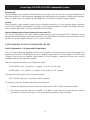
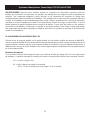
1. WELCOME TO THE CERWIN-VEGA! FAMILY
Congratulations! Welcome to the Cerwin-Vega! family. You’ve joined a growing group of audio professionals
who’ve turned to Cerwin-Vega! for the most advanced audio reproduction systems available. All Cerwin-Vega!
systems are thoroughly tested to insure that they meet or exceed our performance specifications. Backed by the
best service in the industry, Cerwin-Vega! is dedicated to quality and reliability. For a complete overview of
Cerwin-Vega! products and services, log onto www.cerwin-vega.com.
2. OVERVIEW – THE CERWIN-VEGA! CVP-2153 AND CVP-1152 FEATURES
Introducing the CVP Series high performance passive speaker systems from Cerwin-Vega! Professional. The
CVP-1152 (single 15” two-way system) and the CVP-2153 (double 15” three-way system) deliver extreme high
performance, legendary Cerwin-Vega! low frequency reproduction, and excellent sonic quality. Designed to
provide accurate sound reproduction at very high SPL levels, the CVP top box series is performance matched to
stand tough with all of our subwoofer systems, including our folded horns and passive and active direct fire subs.
• New High Performance 15” Driver – We started with a new high performance Cerwin-Vega! 15”
Low/Mid driver in a die cast frame using a 3” voice coil designed to deliver punchy low end and clean,
accurate midrange for high decibel, low distortion performance.
• Mylar Compression Driver for Smooth High End – We integrated a deep drawn high
performance Mylar compression driver that provides low distortion with a smooth high frequency
response and a fast attack transient response. This all means silky high end that has serious throw
capabilities.
• Rugged and Attractive Die Cast Grill for a Clean Cerwin-Vega! System Look – We didn’t stop with the
performance matching either. These full range cabinets also look the part with matched rugged,
die-cast aluminum grills. There will be no doubt that the audience is being entertained by a
full Cerwin-Vega! matched system from looks to performance!
• Rotatable Horn for Concise Pattern Control – The 60 x 40 degree rotatable horn provides flexible
pattern control for install application (or monitor functionality for the CVP-1152).
• Monitor Use for CVP-1152 – The additional 60 degree angle of the CVP-1152 cabinet provides the
ability to lay it on its side for use as a stage monitor. Rotate the horn for better coverage – you can even
rotate the grill so the Cerwin-Vega! logo is oriented correctly! How cool is that!
• Fly Points – We are serious about flexibility and the CVP Full Range Loudspeaker Series delivers.
Twelve Integrated M10 fly points for permanent installations or sound reinforcement applications
requiring overhead suspension are provided.
• Bi Amp Functionality – Use the precise internal cabinet crossover or drive the HF and LF signals
separately with an active crossover and dedicated amplifiers for amazing control and discrete rock
solid high decibel performance.
• High Frequency Driver Protection – A new Cerwin-Vega! designed High Frequency fast reacting relay
circuit suppression limiter provides high-quality protection for the high frequency system.

4
Cerwin-Vega! CVP-2153 & CVP-1152 Loudspeaker Systems
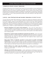
3. BEFORE YOU BEGIN: SAFETY AND CARE FOR YOUR CVP LOUDSPEAKERS
Positioning
High and upper mid frequencies are a crucial part of the audio spectrum, and have much to do with how we
perceive clarity and intelligibility. Whereas these frequencies are the most easily located, they are also the first
to be acoustically blocked. Taking the coverage angles of the models used into consideration, be sure to set up
your speakers so that the MF and HF drivers are free from obstructions and the higher frequencies can reach the
entire audience (e.g. slightly above the heads of the audience). This will ensure optimal dispersion of
higher-frequency content and thus improved speech intelligibility and clarity.
Avoiding Feedback
Always place the "front-of-house” speakers (the enclosures facing the audience) in front of the microphones,
(e.g. towards the front edge of the stage). Use professional floor wedges (e.g. CVP-1152) or other dependable
monitoring systems to ensure that the performers on stage can hear themselves. Whenever possible, position
monitor speakers so that they point only to the back side of microphones.
Avoiding Feedback When Using Turntables (e.g. DJ Applications)
Turntables often produce low-end feedback: low frequencies are fed back to the pickup arm and cartridge and
reproduced again by the speakers. Common causes of low-end feedback are speakers positioned too close to
the turntable or on wooden floors or stage elements prone to vibration. To avoid this, position the speakers as far
from the turntable as possible. Placing them on a solid, non-resonating support will also help. If you are using the
CVP-1152 model speakers, try mounting them on stands. This will minimize direct contact between floor and
speakers and reduce vibration.
Protecting Your Speakers
Next to following common-sense rules like exercising caution while setting levels to avoid overdriving your power
amps, and understanding and respecting the physical limits of your system, there are a couple reliable methods
of protectingyour speakers– and your entire system – usingadditional equipment.Using a high pass filter to avoid
excessive low frequencies, low-frequency rumble or extreme low frequencies can lead to an excessive
displacement of the speaker diaphragm and in turn to permanent damage. Using an equalizer or a low-cut/high
pass filter to eliminate the low frequencies below the response curve of the speaker can effectively prevent this.
Most consoles and outboardequalizers, as well as many other outboard signal processors and of course speaker
management systems provide a high pass filter. The use of a high pass filter in the signal path is especially
recommended when using turntables and/or CD players as signal sources. CD players often produce extremely
low frequencies, which can lead to excessive diaphragm displacement. Using a limiter to limit the output level,
Insert the limiter between the mixing console output and your power amp. Many types of outboard signal
processors and most speaker management systems include limiters for this application. Used properly, they can
eliminate overdriving of your audio signals and effectively suppress dangerous signal peaks, which can not only
degrade the sound quality, but also cause permanent damage to your speakers and other system components.
Power Amplifier Selection
Choosing the right power amplifier has a major effect on the performance of your speakers. The amplifier should
always provide at least as much power as the speaker system is capable of handling. In order to ensure precise
reproduction of brief, high-power transients, the amp should provide about twice as much power as the
speakers can handle.The minimum recommended input power ratings for CVP-1152 and CVP-2153 systems are
displayed in the Specifications Table.

5
Cerwin-Vega! CVP-2153 & CVP-1152 Loudspeaker Systems
Cable Selection
The quality and characteristics of the speaker cables used also greatly effect speaker performance. Always use
high-quality cables made with professional-grade wire and connectors that are correctly and carefully fitted.
Selection of the appropriate wire gauge is especially important to system operation. A cable that is too light or
low-gauge will result in amplifier power being wasted due to the series resistance of the cable and in loss of
low-frequency performance due to degraded damping factor. The ideal gauge is determined by two factors: the
length of the cable and the load or impedance. For cable runs up to 50 feet (15m) with an 8-Ohm load, we
recommend using at least 14-gauge wire – 12-gauge is minimum for a 4-Ohm load. For runs between 50 and 100
feet (15-30m), use at least 12-gauge for 8-Ohm loads and 10-gauge for 4 Ohms. At 200 feet (60m), you should
use 10-gauge and 8-gauge, respectively, and so on.
Using Poles, Tripod Mounts, and Speaker Movement Due to Vibrations
The Cerwin-Vega! CVP speakers covered by this manual are designed for portable applications in which the
speakers will be stacked directly on the floor, stage, a solid stable platform, mounted on a tripod stand or
pole-mount. (Pole and tripod mounting only applies to the CVP-1152). The CVP Series also may be suspended
using industry standard, forged M10 eye bolts. Please refer to the suspension warnings and instructions further
in this document.
THESE SPEAKERS ARE HEAVY!
Please use common sense and adhere to the manufacturer’s hardware ratings when placing speakers on stands
or poles. Never exceed the rated safety limit of a pole or speaker stand. Never place a speaker on a pole or
tripod that is leaning at an angle as the speaker may tip over.
Cerwin-Vega! Professional speakers can generate considerable energy. When placed on a slippery surface such
as polished wood or linoleum, the speaker may move due to vibration caused by its acoustical energy output.
Precautions should be taken to assure that the speaker does not fall off a stage or platform on which it is placed.
The Cerwin-Vega! CVP-1152 speaker model includes a receptacle cup to allow mounting on tripod stands
or poles. When using stands or poles, be sure to observe the following precautions:
• Check the stand specification to be certain it is designed to support the weight of the speaker.
• Observe all safety precautions specified by the stand manufacturer.
• Always verify that the stand is placed on a flat, level, and stable surface and be sure to fully extend the
legs of tripod type stands. Position the stand so that the legs do not present a trip hazard.
• Route cables so that performers, production crew, and audience will not trip over them pulling the speaker
over.
• Do not attempt to place more than one speaker on a stand designed for a single speaker.
• Always be cautious in windy, outdoor conditions. It may be necessary to place additional weight
(i.e. sandbags) on the base of the stand to improve stability.
• Unless you are confident that you can handle the weight of the speaker, ask another person to help
you lift it onto the tripod stand or pole.
Moisture
Moisture can damage the speaker cone and surround and cause corrosion of electrical contacts. Avoid
exposing the speakers to direct moisture. Keep speakers out of extended or intense direct sunlight. The driver
suspension will prematurely dry out and finished surfaces may be degraded by long-term exposure to intense
ultra-violet (UV) light.

6
Cerwin-Vega! CVP-2153 & CVP-1152 Loudspeaker Systems
Powering Up
To avoid damage to your speaker and other parts of your system, when you turn On your system, always turn On
the power amp last! This will avoid loud, damaging pops that will annoy your audience, and blow your speakers.
When you power down, the amplifier should always be turned Off first to avoid the same problems.
Polarity
When using two or more speaker systems, be sure to match the polarity (+/-) of the speaker system connectors
to those of the amplifier. If polarities do not match, the sounds produced by the speaker will interfere with each
other, making it impossible to achieve a well-balanced sound field.
Hearing damage and prolonged exposure to excessive SPL
CVP Series loudspeakers are easily capable of generating sound pressure levels (SPL) sufficient to cause
permanent hearing damage to performers, production crew, and audience members. Proper precautions should
be taken to avoid prolonged exposure to SPL in excess of 85 dB.
4. SET UP AND USE OF THE CVP-2153 AND THE CVP-1152
Input Configurations / Full Range and Bi Amp Modes
The CVP Series models are equipped with both a 4-pin Speakon connector and two 1/4” phone jack inputs. The
speakers provide FULL RANGE mode where one amplifier signal powers the entire speaker or BI AMP mode
(Speakon only) where one amplifier signal powers the high frequency compression driver and a second
amplifier powers the low frequency driver(s).
The 4-pin Speakon connectors are configured as follows:
- FULL RANGE mode: 1+ positive / 1- negative. (2+ and 2- are not used)
- BI AMP mode: 1+ LF positive / 1- negative, 2+ HF positive / 2- HF negative.
The quarter inch phone jacks are configured as follows:
- FULL RANGE mode only: Tip positive / Sleeve negative.
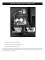
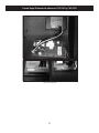
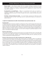
To change the system to Bi Amp mode follow these directions:
1. Remove the grill (twelve screws) and woofer (eight screws) NOTE: Woofer connection polarity.
2. Move the wire harness from “FULL RANGE” to “BI AMP” on the input circuit board and the crossover
circuit board. Please check (Figure 1, Full Range Mode), displayed on the next page.

7
Cerwin-Vega! CVP-2153 & CVP-1152 Loudspeaker Systems
3. Ensure the connector is seated properly.
4. Reconnect the woofer and tighten all eight screws.
5. Reinstall the grill with all twelve screws.
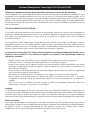
To change the system back to Full Range mode see steps 1-5 above, but move the wire harness from “BI AMP”
to “FULL RANGE” on the input circuit board and the crossover circuit board. Please check (Figure 2, Bi Amp
Mode), displayed on the next page.
Figure 1, Full Range Mode

8
Cerwin-Vega! CVP-2153 & CVP-1152 Loudspeaker Systems
Figure 2, Bi Amp Mode

9
Cerwin-Vega! CVP-2153 & CVP-1152 Loudspeaker Systems
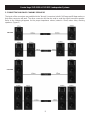
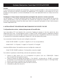
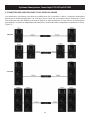
5. CONNECTING AND DAISY CHAINING SPEAKERS
The inputs of the connectors are paralleled to the “through” connectors in both Full Range and Bi Amp modes so
that either connector will work. The other connector can then be used to send the signal to another speaker.
Refer to the following diagrams for the proper impedance values (stated in Ohms) when daisy chaining
speakers. (Figure 3)
Figure 3
CVP-1152
CVP-2153

10
Cerwin-Vega! CVP-2153 & CVP-1152 Loudspeaker Systems
6. HIGH FREQUENCY FAST REACTION PROTECTION CIRCUIT
Your CVP speakers offer a fast reacting suppression limiter that senses input voltage and reduces potentially
damaging voltage levels that would otherwise reach your high frequency drivers.
7. ROTATABLE HORN
The high frequency horn in the CVP series is installed in a 60 degree horizontal and a 40 degree vertical
orientation. The horn can be rotated to provide 40 degrees vertically and 60 degrees horizontally for an
alternative high frequency dispersion pattern which is useful in certain install situations or when using the
CVP-1152 as a floor monitor.
Remove the screws, then rotate the horn 45 degrees, and replace the screws being careful not to apply too much
torque pressure.
8. USING THE CVP-1152 AS A FLOOR MONITOR
The CVP-1152 can be used as a floor monitor. Typically, you will want more high frequency coverage from left to
right across your stage or performance area. Follow the instructions earlier in this document to rotate the horn.
Note that you can even rotate the grill to orient the Cerwin-Vega! logo in the correct position! How cool is that?
To rotate the grill, first remove the grill screws. Pull the grill out and turn it 90 degrees. Replace the screws being
careful with the torque pressure applied.
9. WARNING ABOUT SUSPENDING LOUDSPEAKERS
The CVP Series uses forged M10 eye bolts.
Only use eye bolts that are professionally certified for the proper 10x load requirements.
Suspending loudspeakers is serious business! Injury or death can occur if loudspeaker systems are not
suspended correctly! Read and follow these instructions carefully!
Speaker suspension must take place in accordance with instructions provided by Cerwin-Vega! and under the
supervision of a licensed, professional sound/rigging engineer or structural engineer. Only use attachments,
mounts, accessories, or brackets specified by Cerwin-Vega! or only specified products rated for overhead
suspension. Refer all servicing to qualified personnel. Servicing is required when the apparatus has been
damaged in any way.
WARNING! Before placing, installing, rigging, or suspending any speaker product, inspect all hardware, suspension, cabinets,
transducers, brackets and associated equipment for damage. Any missing, corroded, deformed or non-load rated component
could significantly reduce the strength of the suspension, placement, or array. Any such condition severely reduces the safety
of the suspension and should be immediately corrected. Use only hardware which is rated for the loading conditions of the
suspension and any possible short-term unexpected overloading. Never exceed the rating of the hardware or equipment.
Consult a licensed, professional engineer when any doubt or questions arise regarding a physical equipment installation.
Cerwin-Vega! is not responsible for damage or liability for improperly installed or maintained mounting and/or rigging systems.

11
Cerwin-Vega! CVP-2153 & CVP-1152 Loudspeaker Systems
10. SUSPENSION OF THE CVP SERIES
Remove the fly bracket screws in the fly points where you want to install M10 eye bolts. Screw in the M10 eye
bolts being careful not to strip the fly bracket screw insert point. Do not remove fly bracket screws from areas
where you will not install eye bolts – insure that either an eye bolt or a fly bracket screw is installed in all fly
bracket screw insert locations.
De-rating
Using the mounting points at an angle will de-rate the WLL (Working Load Limit) for each mounting point. Each
point mounted at an angle should be de-rated according to the following formula.
- WLL = cosine (angle) x 500
- Where: angle = degrees form vertical pull
500 = WLL for each CVP mounting point @ vertical pull
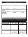
11. SPECIFICATIONS
Cerwin-Vega! Loudspeaker Systems
CVP-1152 CVP-2153
Frequency Range -10 dB 50 Hz - 20 kHz 37 Hz - 20 kHz
Frequency Response -3 dB 59 Hz - 18.5 kHz 48 Hz - 18.5 kHz
Sensitivity @ 1w / 1 Meter 99 dB 101 dB
Power Capacity RMS / PK 500 / 1000 w 1000 / 2000 w
Recommend Amplifier Power 750 w - 1000 w 1500 w - 2000 w
Maximum SPL 130 dB 134 dB
Coverage Pattern 60 x 40 rotatable 60 x 40 rotatable
HF Diaphragm Size 1.75” 1.75”
Weight 66.5 lbs 112.5 lbs
Fly Points Yes Yes
Bi Amp use Yes Yes
Rotatable Horn Yes Yes
HF Protection Fast Reacting Suppression Limiter
Woofer Ceramic 3” VC
Construction Multi-ply Hardwood
Finish Polyurethane Paint

12
Cerwin-Vega! CVP-2153 & CVP-1152 Loudspeaker Systems
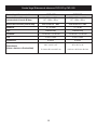
Cerwin-Vega! Loudspeaker Systems
CVP-1152 CVP-2153
Recommended Amplifier Power in
Bi Amp Mode
LF - 750wto 1000 w
HF - 100w-150 w
LF/MF - 1500wto 2000 w
HF - 100w-150 w
Bi Amp Crossover Settings
CVP-1152 LPF/HPF CVP-2153 LPF / HPF
Gain 0 / -12.5 dB 0 / -10 dB
Type Linkwitz-Riley Linkwitz-Riley
Slope -12 dB Oct / -12 dB Oct -12 dB Oct / -12 dB Oct
Freq 2 kHz/2 kHz 2 kHz / 2 kHz
Impedance 8 Ohms 4 Ohms
Dimensions (HxW x D)
28.1”x18.2”x16”
71.4 cmx46.2 cmx40.7 cm
45”x18.2”x19”
114.3 cmx46.2 cmx48.3 cm

13
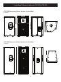
Cerwin-Vega! CVP-2153 & CVP-1152 Loudspeaker Systems
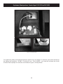
28.1” (71.4cm)
18.2” (46.2cm)
16” (40.7cm)
CVP-1152 Dimensions (H x W x D)
(Figure 4)
CVP-2153 Dimensions (H x W x D)
(Figure 5)
19” (48.3cm)
45” (114.3cm)
18.2” (46.2cm)
Figure 4
Figure 5
Page is loading ...
Page is loading ...
Page is loading ...
Page is loading ...
Page is loading ...
Page is loading ...
Page is loading ...
Page is loading ...
Page is loading ...
Page is loading ...
Page is loading ...
Page is loading ...
Page is loading ...
Page is loading ...
Page is loading ...
Page is loading ...
Page is loading ...
Page is loading ...
Page is loading ...
Page is loading ...
Page is loading ...
Page is loading ...
Page is loading ...
Page is loading ...
Page is loading ...
Page is loading ...

LITP00045 REV-B 8/28/2012
Phone: 1-800-4GIBSON (1-800-444-2766)
Cerwin-Vega! A member of the Gibson family of brands
www.cerwin-vega.com
Cerwin-Vega! reserves the right to make changes to product specification and design at any time.
© Copyright 2012 Cerwin-Vega!
-
 1
1
-
 2
2
-
 3
3
-
 4
4
-
 5
5
-
 6
6
-
 7
7
-
 8
8
-
 9
9
-
 10
10
-
 11
11
-
 12
12
-
 13
13
-
 14
14
-
 15
15
-
 16
16
-
 17
17
-
 18
18
-
 19
19
-
 20
20
-
 21
21
-
 22
22
-
 23
23
-
 24
24
-
 25
25
-
 26
26
-
 27
27
-
 28
28
-
 29
29
-
 30
30
-
 31
31
-
 32
32
-
 33
33
-
 34
34
-
 35
35
-
 36
36
-
 37
37
-
 38
38
-
 39
39
-
 40
40


Cerwin-Vega CVP-1152 User manual
- Category
- Soundbar speakers
- Type
- User manual
- This manual is also suitable for
Ask a question and I''ll find the answer in the document
Finding information in a document is now easier with AI
in other languages
- français: Cerwin-Vega CVP-1152 Manuel utilisateur
- español: Cerwin-Vega CVP-1152 Manual de usuario
Related papers
-
Cerwin-Vega CVP-1152 User manual
-
Cerwin-Vega CVI Series User manual
-
Cerwin-Vega EL36 User manual
-
Cerwin-Vega P1500X User manual
-
-
-
-
-
-
Other documents
-
Yamaha NS-IW360C User manual
-
cerwin vega CERWIN-VEGA VIS-153 Professional Loudspeaker Systems Owner's manual
-
AUDAC VEXO110-B User manual
-
Optimus PJ-100 User manual
-
Premier BB-1869 User manual
-
3M MA240MB User manual
-
 Audibax PR42T Owner's manual
-
 Snell Advanced Media Vega 200 Installation guide
-
Yamaha S15e User manual
-
Work-pro MINO 12 User manual

