Carrera 23613 GENTLEMEN RACE Owner's manual

Category
Toy vehicles
Type
Owner's manual

This manual is also suitable for

23613 GENTLEMEN RACE
Montage- und Betriebsanleitung
Assembly and operating instructions
Instructions de montage et d’utilisation
SET
CHANNEL
SET
CHANNEL
SET
CHANNEL
2
1x
1x
1x
96x
6x
1x 90°/100 cm/39.37 inch
Q
1x 150 cm/59.05 inch
R
3x 240°/232 cm/91.34 inch
S
300x
8x
G
7x
L
7x
M
12x
N
12x
O
6x
H
6x
I
6x
K
12x
F
3x
1x
A
1x
B
7x
E
8x
C
1x
3x
D
1x
AU
Special
1x
PT
1x 1x
1x
SET
CHANNEL
3x
3
,7
V
1
5
0
m
h
A
2x
6x
6x
2x 44 cm/17.32 inch
P
1x1x
S
S
S
P
P
Q
R
A
B
C
C
C
C
C
G
N
N
N
N
N
N
N
N
N
N
N
N
G
G
G
G
G
G
G
C
C
D
D D
F
F F
F
F
F
F
E
F
F
F
F
E
E
E
F
E
E
E
C
AU
PT
K
K
O
O
O
O O
O
O
O
O
O
O
O
K K H H
H
K
K
I
M
M
M
L
L
L
L
M
M
M
M
I
I
L
L
L
I
I H H
H
I
AU AU
PT PT
Alternative Aufbauvorschläge · Extension proposal · Suggestion d‘extension
Verpackungsinhalt · Contents of package · Contenu du carton
23613 GENTLEMEN RACING
Hergestellt mit der Zustimmung der
Dr. Ing. h.c.F. Porsche AG.
Produced under license of Ferrari Spa. FERRARI,
the PRANCING HORSE device, all associated
logos and distinctive designs are property of
Ferrari Spa. The body designs of the Ferrari cars
are protected as Ferrari property under design,
trademark and trade dress regulations.
“Aston Martin”, “Aston Martin Racing” and
related logos and other trademarks are
owned, licensed and/or used by Aston Martin
and Aston Martin Racing. These trademarks
may not be used, amended and/or reproduced
without permission. All rights are reserved.
OFFICIAL
LICENSED
PRODUCT
4
11
18
Montage- und Betriebsanleitung · Technische und designbedingte Änderungen vorbehalten
Assembly and operating instructions · Subject to technical and design-related changes
Instructions de montage et d’utilisation · Sous réserve de modifications techniques ou de design
SET
CHANNEL
7
8
1
56
3
9
2
4
9
11
Table of contents
Safety instructions 11
Declaration of Conformity 11
Contents of package 11
Technical advice for assembly 11
Important Information 12
Description 12
Before first use 12
Care of the battery 12
Assembly instructions 12
Guard Rails and Supports 12
Electrical connection 12
Car components 12
Connections Control Unit 13
Connecting the receiver 13
Connecting the charging unit 13
Connecting the Position Tower 13
Displays 13
Charging the speed controllers 13
Binding process 13
Control elements Control Unit 14
Encoding/programming
of cars to the according speed controllers 14
Preparation of start 14
Points function 14
Light function on/off 14
Encoding/programming of Autonomous Car 14
Encoding/programming Pace Car 14
Display of position Autonomous and Pace Car 15
Setting of the cars´ basic speed 15
Setting of cars´ braking performance 15
Setting fuel tank capacity 15
Extended Pit Lane function 16
Sound ON/OFF 16
Reset function 16
Energy-saving mode 16
Replacement of double sliding contact and guide keel 16
Height adjustment car chassis 16
Changing the light board 16
Maintenance and care 17
Troubleshooting/Driving tips 17
Technical specifications 17
Requirement for FCC Part 15 17
Warnings 17
Welcome
Welcome to the Team Carrera!
These operating instructions contain important information regarding
the assembly and operation of your Carrera DIGITAL 124 racetrack.
Please read them carefully and keep them in a safe place afterwards.
If you have any queries, please do not hesitate to contact our dis-
tributor or visit our websites: carrera-toys.com · carreraclub.com
Please check the contents for completeness and possible transport
damage. The packaging contains important information and should
also be retained. We hope you will derive a lot of pleasure from your
new Carrera DIGITAL 124 track.
Safety instructions
WARNING! Not suitable for children under 36 months. Danger of
suffocation due to small parts which may be swallowed. Caution: risk
of pinching caused by function.
WARNING!
This toy contains magnets or magnetic components. Magnets at-
tracting each other or a metallic object inside the human body may
cause serious or fatal injuries. Seek medical attention immediately if
magnets are swallowed or inhaled.
The transformer is not a toy! Do not short-circuit the transformer’s
connections! Note to parents: Regularly inspect the transformer for
damage to the cable, plug or housing! Only operate the toy with rec-
ommended transformers! The transformer may no longer be used
if it is damaged! Only operate the racetrack with a transformer! If
play is interrupted for longer periods, it is recommended to separate
the transformer from the power supply. Do not open transformer or
speed controller housings!
Important note to parents:
Transformers and power supply units are not suitable to be used as
toys. The use of such products needs to be constantly supervised
by the parents.
Regularly check the track and cars for damage to cables, plugs
and housings! Replace defective parts.
The car racetrack is not suitable for outdoor operation or operation
in wet locations! Keep away from liquids.
Do not place any metal parts onto the track to avoid short-circuits.
Do not place the track in the immediate vicinity of delicate objects, as
these could be damaged by cars hurled from the track.
Pull the plug before cleaning the racetrack! Only use a damp cloth
for cleaning, no solvents or chemicals. When it is not in use, store
the track in a dry and dust-protected location, preferably in the origi-
nal cardboard box.
Do not operate race track at face- or eye-level risk of injury due
to cars being catapulted off the track.
Misuse of transformer can cause electrical shock.
The toy is only to be connected to Class II equipment
bearing the following symbol.
The toy must only be used with a transformer for toys.
Note:
The vehicle may only be operated again in a completely assembled
condition. Assembly may only be carried out by an adult.
This appliance is not intended for use by persons (including children)
with reduced physical, sensory or mental capabilities, or lack of ex-
perience and knowledge, unless they have been given supervision
or instruction concerning use of the appliance by a person responsi-
ble for their safety. Children should be supervised to ensure that they
do not play with the appliance.
Instruct the child not to try and recharge non-rechargeable batteries
because of the danger of explosion.
Declaration of Conformity
The company Stadlbauer Marketing + Vertrieb GmbH, hereby con-
firms that the product „2.4 GHz WIRELESS+“ complies with the fun-
damental requirements of Guideline 1999/5/EC (R&TTE).
The Declaration of Conformity can be called up from the following
address: www.carrera-toys.com
Contents of package
1 Porsche GT3 RSR “BMS Scuderia Italia, No.97”, 2010
1 Aston Martin DBR9 “Team Modena, No.59”
1 Ferrari 599XX, Ferrari Racing Days “No.88”
8 Standard straights
3 1/3 straights
1 Control Unit
1 Position Tower
1 Adapter Unit
1 Carrera DIGITAL 124 double lane change section (2 track parts)
1 Carrera DIGITAL 124 lane change section, right (2 track parts)
7 Curves 1/60°
12 Curves 3/30°
3 WIRELESS+ Speed controllers
1 WIRELESS+ Receiver
1 WIRELESS+ Twin charging station
1 WIRELESS+ Single charging station
Technical advice for assembly
1
Connecting track + Control Unit
2
WIRELESS+ Receiver
3
WIRELESS+ Twin charging station
4
WIRELESS+ Single charging station
5
Double lane change section input
6
Double lane change section output
7
Lane change section right input
8
Lane change section right output
9
Infrared sensor:
The infrared sensor MUST be located on the switch that
functions as the entry rail (dark diode).
12
3 LiPo rechargeable battery for speed controller
1 Transformer
1 Special track
1 Grid Girls
1 Golden plated winners cup
Outside shoulders for curves
Inside shoulders for curves
Shoulder end sections
Guard rails
Track section bolts
Replacement contacts
Instructions
Track length: 39.37 ft./ 12,0 m
Dimensions when assembled: 14.27 x 10.99 ft./ 435 x 335 cm
Important Information
Carrera DIGITAL 124EXCLUSIV
Carrera DIGITAL 124 EXCLUSIV
Please note that Exclusiv (analog system) and Carrera DIGITAL
124/132 (digital system) involve two separate and completely inde-
pendent systems. We hereby expressly indicate that both systems
must be kept separate when setting up the track, i.e. no connecting
rail from Exclusiv may be used together with the connecting rail and
Black Box of the Carrera DIGITAL 124/132, even if only one of the
two connecting rails (Exclusiv connecting rail or Carrera DIGITAL
124/132 connecting rail and Black Box) is attached to the current
supply. Furthermore, no other Carrera DIGITAL 124/132 compo-
nents (switches, electronic lap counter, pit stop) may be built into an
Exclusiv course, i.e. via analog operation.
Non-compliance with the above information may result in damage or
destruction of the respective Carrera DIGITAL 124/132 components.
In this case no warranty may be claimed.
Description
WIRELESS+ is the latest new cordless racetrack delight for Carrera
DIGITAL124 and Carrera DIGITAL 132. The 2.4 GHz radio technolo-
gy with frequency-hopping is free of interference and offers a range
of up to 15 metres. Thanks to powerful lithium polymer rechargeable
battery, continuous play for up to eight hours is possible and stand-
by operation for over 80 days. WIRELESS+ offers cordless freedom
for up to six drivers at the racetrack.
Before first use
Before first using the speed controller, the rechargeable battery
supplied
2
must be inserted in the controller. Unscrew the battery
compartment
1
on the underside of the speed controller.
Connect the battery plug into the socket in the speed controller and
put the battery in place in the compartment. Finally screw down the
cover of the battery compartment again. The battery is part-loaded
at the factory, but it should be charged completely before being
used for the first time.
3
,7
V
1
5
0
m
h
A
2
1
1
Care of the battery
To make sure the battery performs well for as long as possible, the
following points should be observed regarding its care and storage.
Before first using them, new batteries should always be charged
fully.
With a fully-charged battery, continuous play is possible for up
to eight hours. When the battery power is falling off, range of the
speed controller will diminish. As soon as you notice this, the battery
should be fully recharged.
If it is not to be used for an extended period, remove the battery
and store the controller at room temperature (16-18 °C) in a dry
place. To prevent a deep discharge of the battery, the stored battery
should be charged every 2 to 3 months.
Assembly instructions
1 4
2 3
1
+
2
+
3
Before assembling please insert the connecting clips
in the track as shown in figure
1
. Stick tracks together on a flat
base. Move the connecting clips according to figure
2
in direction
of the arrow until they audibly snap in. The connecting clip may also
be inserted later. The connecting clips can be removed into both
directions by simply pressing down the clamped nose (see fig.
3
).
4
Fastening: To fasten the track sections on a board, it is neces-
sary to use the track section fasteners (Item no. 85209, not con-
tained in the package).
Note:
Carpeting is not a suitable foundation on which to build the track be-
cause of static charging, formation of fluff and ready inflammability.
Guard Rails and Supports
1 2
3 4
1
Guard rails: Guard rail mounts are fitted by tilting them upwards
onto the verge of the track.
2
+
3
Supporting raised sections: The shank of the ball pivot is
to be inserted into the square slots provided on the underside of the
track. The supports can be made higher by using the extensions.
The pedestal of the supports can be screwed to a base if required
(screws not included).
4
Supporting steep curves:
Slanting supports of the right height are provided to support steep
curves. Fix the nonadjustable supports at the beginning and end of
the curves. Insert the heads of the supports in the round slots of the
underside of the track.
Electrical connection
1
1
Connect the transformer plug with the Control Unit.
Note: To avoid short-circuits and electrocution, the toy may not be
connected using foreign devices, plugs, cables or other objects for-
eign to this toy. The Carrera DIGITAL 124 car racetrack only works
properly with an original Carrera DIGITAL 124 transformer.
The PC interface (PC Unit) may only be operated together with the
original Carrera PC Unit.
Car components
3
6
5
3
12
13
11
3
4
15
14
2
3
7
10
8
9
1
1
Body
2
Engine block
3
Tyres
4
Rear axle
5
Rear axle receptacle
including spacer plate
6
Front axle
7
Front axle mounting
8
Board
9
Central magnet
10
Rear magnet
11
Chassis
12
Rocker arm including spring
13
Guide keel with double sliding contact
14
Center magnet retainer
15
Fastening plate
Note: vehicle construction depends on the model.
The designation of the individual parts may not be used as
order numbers.
13
Connections (from left to right):
1
Connection for Lap Counter 30342
2
Connection for PC-unit or Lap Counter 30355
3
Connector 1 for speed controller, speed controller extension set
or WIRELESS+ receiver
4
Connector 2 for WIRELESS Tower 10108
5
Connector 3 for speed controller
6
Connector 4 for speed controller
7
Connection for DIGITAL 124 / DIGITAL 132 power supply
General information on connectors 1-4:
When a WIRELESS+ receiver is used, it must be plugged into con-
nector 1. Optionally a WIRELESS Tower 10108 can be plugged into
connector 2. When only the WIRELESS+ receiver is used, connec-
tor 2 is to be left empty.
Additional wired speed controllers may be plugged into connectors
3 and 4. Please note that these will use address 5 and 6 then.
Using the speed controller extension set 30348 it has to be plugged
into connector 1. The cars´ addresses will be allocated as follows:
Speed controller extension set = address 1, 3 and 4
connector 2 = address 2
connector 3 = address 5
connector 4 = address 6
Note:
a combination of WIRELESS and speed controller extension set is
not possible!
Connections Control Unit
1 52 63 74
Connecting the receiver
Connect the receiver according to the symbol to either of the two
sockets on the control unit which are marked Tower 1 and Tower 2.
For operating six WIRELESS+ speed controllers only one 2.4 GHz
receiver is required.
Symbols
SET
C
H
A
N
N
E
L
Connecting the charging unit
The charging unit is connected at the rear of the control unit. To site
the charging unit at any other place on the track, an adapter unit
30360 will be needed.
Rear view of the
control unit
Connecting the Position Tower
AU
PT
The Position Tower
is suitably connected to the Adapter Unit
; the latter can be positioned at any place within the racetrack.
Displays
21
1 a
1 b
1
Two-digit LED-segment display to indicate the number of laps
1
a
Display 100 laps
1
b
Display 200 laps
2
One-digit LED-segment display to indicate race position of 6
cars maximum
Charging the speed controllers
Before first being used, the WIRELESS+ speed controllers should
be fully charged. Place the speed controllers in the charging station
and switch on the control unit. While the unit is charging, the LEDs
1
on the speed controllers will flash. When charging is completed,
the LEDs
1
will light up continuously.
When using a lithium polymer rechargeable battery, it is possible to
top up the speed controller at any time.
1 1
Binding process
2
SET
CHANNEL
1
2
3
1
SET
CHANNEL
1
4
2
1
3
SET
CHANNEL
1
2
3
Before the speed controller can be used to control the cars, it must
be “bound” to the receiver.
To do this, switch on the control unit.
1
The receiver indicates it is ready for operation by a revolving light
signal in the segment display
1
.
2
Push the “SET” button
2
once until the figure 1 appears in the seg-
ment display
1
. The number shown is then the address of the car.
Switch to the next address by further pressing the button.
Now press the binding button
3
on the top of the speed controller.
The speed controller signals a successful binding process with
flashing of the LED, while the receiver indicates it by revolving lights
in the segments. The binding process is now complete and the
speed controller is ready for use.
3
To bind the second speed controller, follow the same procedure.
Press the “SET” button
2
on the receiver twice, until the figure
2 appears
1
. Then press the binding button
3
on the second
speed controller.
4
To display the address set for the speed controller, press once on
the binding button
2
on the top of the speed controller.
The LED
1
will then flash, according to the address set.
If the speed controller is not actuated, it switches automatically after
about 20 seconds into energy-saving mode. The speed controller
can be reactivated by pressing the tappet or the lane-change button.
14
Control elements Control Unit
1
8
2
7
3
6
4
5
1
On/off switch
2
Switch for fuelling function
3
Button to start the race / acknowledge programming
4
Button for Pace Car / termination of programming
5
Button for setting basic speed
6
Button for setting braking performance
7
Button for setting fuel tank capacity
8
Programming button for cars
General operating information
Some buttons are assigned with different tasks. In order to set a
function you need to use key combinations. Any programming steps
can be cancelled with button
4
“ESC/PACE CAR″. You will find
further details in the course of this manual.
Encoding/programming
of cars to the according
speed controllers
1
8
2
7
3
6
4
5
1 2
1x
3 4
To encode a car place it on the track and swich on the Control Unit.
Press “Code” button once
8
, fig.
1
; the first LED starts to light,
fig.
2
. Then push lane-change-button once on the relevant speed
controller, fig.
3
. In case the car is equipped with lights they will
start to flash and the Control Unit´s LEDs 2-4 will light successively.
Once encoding has been carried out the middle LED lights perma-
nently (fig.
4
) and the car is allocated to the speed controller.
Note: This kind of encoding requires to only have the car on the
racetrack which shall be encoded.
Preparation of start
1 2
This Carrera DIGITAL 132 vehicle ideally matches the Carrera track
system scale 1:24.
1
+
2
Optimally setting up the grinders:
To ensure proper and continuous driving, slightly fan out the ends
of the contact brushes
1
and bend them towards the track as per
fig.
2
. Only the end of the contact brush should have contact to the
track and may be cut off slightly in case of wear. Dust and abrasion
should be removed from track material and sliding contacts from
time to time.
During operation small car parts as spoilers or mirrors may get off or
brake due to being original detailed parts of the car model. To avoid
this it is possible to remove them before operation.
Points function
2
1
1
Make sure that the car’s guide keel is located inside the track
slot and that the double sliding contact is in contact with the current
carrying track.
Place the cars onto the connecting track.
2
When changing lanes, you must keep the button on the
speed controller depressed until the car has passed the point.
Light function on/off
3 sec.
STOP
The car programmed to the speed controller will have to come to a
stop for at least 3 seconds before the light can be switched on or off
by the push of the lane-change-button.
Note:
applies only to models fitted with lighting
Encoding/programming
of Autonomous Car
1
8
2
7
3
6
4
5
1 2
2x
3 4
300
150
250
200
0
100
50
SPEED
+
CLICK
5
Switch on the Control Unit, place the car to be encoded on the
track and press „Code“
8
twice, fig.
1
. The first two LEDs at the
Control Unit start to light, fig.
2
. Now push the lane-change but-
ton at the speed controller, fig.
3
; LEDs 3-5 will light successively.
Wait until the middle LED lights again, fig.
4
. Activate the speed
controller´s tappet until the car has reached the desired speed. Now
push lane-change button again, fig.
5
.
Autonomous Car´s encoding is completed now.
Note: This kind of encoding requires having only the car on the
track which is to be encoded. The programming of the Autono-
mous Car will be maintained unless the car is not being recoded.
The Autonomous Car is always displayed with address 7 in combi-
nation with the Position Tower.
Encoding/programming
Pace Car
Pit Lane 30356
1
8
2
7
3
6
4
5
2
3x
1
3 4
300
150
250
200
0
100
50
SPEED
+
CLICK
5
(only in combination with Pit Stop Lane #30356)
Switch on the Control Unit, place the car to be encoded on the track
and press “Code″
8
three times, fig.
1
. The first three LEDs at
the Control Unit start to light, fig.
2
. Now push the lane-change but-
ton at the speed controller, fig.
3
; LEDs 2-5 will light successively.
Wait until the middle LED lights again, fig.
4
. Activate the speed
controller´s tappet until the car has reached the desired speed. Now
push lane-change button again, fig.
5
. The Pace Car´s encoding is
completed now and the car enters the Pit Stop Lane.
Note: This kind of encoding requires having only the car on the
track which is to be encoded. The programming of the Pace Car
will be maintained unless the car is not being recoded. The Pace
Car is always displayed with address 8 in combination with the Posi-
tion Tower.
Extended Pace Car function
After the Pace Car´s encoding has been completed it will auto-
matically enter the Pit Lane during the first laps. In order to start the
Pace Car please push the button “Pace Car”
4
once. The LEDs
2 and 3 at the Control Unit will light and the Pace Car will leave the
Pit Lane. The Pace Car will now drive as long as the button „Pace
Car“ is pushed again. LED 2 stops lighting and the car automatically
enters the Pit Lane within the current lap.
15
Display of position
Autonomous and Pace Car
1
8
2
7
3
6
4
5
1
Position
Tower
30357
1
8
2
7
3
6
4
5
3
1
8
2
7
6
4
5
2
(only in combination with Position Tower #30357)
The position of the Autonomous Car (address 7) and of the Pace
Car (address 8) can be displayed at the Position Tower. This func-
tion can be activated at the Control Unit. Therefore switch off the
Control Unit and keep the “BRAKE” button
6
pushed, fig.
2
,
switch on the racetrack and release the “BRAKE” button again. By
pushing the button again the function may be changed:
1 LED lights = no display
2 LEDs light = display at the Position Tower
Set the function requested and confirm your choice via “START/
ENTER”.
Setting of the
cars´ basic speed
1 – 10 1 – 10
1 2
1
8
2
7
3
6
5
4
1
8
2
7
3
6
4
5
3
6
1
8
2
7
3
6
4
5
5
The setting of the basic speed can be effected individually for one
and/or several cars. The cars which are to be adjusted have to be
positioned on the track. The setting can be carried out on 10 levels
with the 5 LEDs indicating the different levels by flashing or perma-
nent lighting.
1
1 LED lights = low speed
2
5 LEDs light = high speed
Switch on the Control Unit, place the cars to be adjusted on the
track and press “SPEED”
5
once. A certain number of LEDs will
now light, showing the speed level last used. Push the “SPEED”
button
5
as many times until you have reached the speed desired.
Confirm by pressing “ENTER/START”
3
. A short running light and
the lighting of the middle LED confirms completion of the setting,
fig.
6
.
Setting of cars´
braking performance
1 – 10
1 – 10
1 2
1
8
2
7
3
6
5
4
1
8
2
7
3
6
4
5
3
6
1
8
2
7
3
6
4
5
5
(only for cars operated with speed controllers)
The setting of the braking performance can be effected individually
for one and/or several cars. The cars which are to be adjusted have
to be positioned on the track. The setting can be carried out on 10
levels with the 5 LEDs indicating the different levels by flashing or
permanent lighting.
1
1 LED lights = low braking effect
2
5 LEDs light = high braking effect
Switch on the Control Unit, place the cars to be adjusted on the
track and press “BRAKE”
6
once. A certain number of LEDs will
now light, showing the brake step last used. Push the “BRAKE” but-
ton
6
as many times until you have reached the braking perfor-
mance desired. Confirm by pressing “ENTER/START”
3
. A short
running light and the lighting of the middle LED confirms completion
of the setting, fig.
6
.
Setting fuel tank capacity
1 – 10
1 – 10
1 2
1
8
2
7
3
65
4
1
8
2
7
3
6
4
5
3
6
1
8
2
7
3
6
4
5
5
(only for cars operated with speed controllers)
The setting of the fuel tank capacity in combination with the Pit Lane
(30356) is effected for all cars simultaneously. The setting can be
carried out on 10 levels with the 5 LEDs indicating the different lev-
els by flashing or permanent lighting.
1
1 LED lights = low fuel capacity
2
5 LEDs light = full tank
Switch on the Control Unit, place the cars to be adjusted on the
track and activate the fuelling function by means of the slide switch
2
, fig.
3
. Press the “FUEL” button
7
once. A certain number of
LEDs will now light, showing the fuel capacity last used. Push the
“FUELbutton
7
as many times until you have reached the fuel
capacity desired. Confirm by pressing “ENTER/START”
3
. A short
running light and the lighting of the middle LED confirms completion
of the setting, fig
6
.
Extended fuelling function
You can choose between 3 modes via the sliding switch
2
,
fig.
3
:
OFF = cars don´t consume any “petrol”
ON = cars consume “petrol”
REAL = maximum speed depending on fuel tank capacity / cars
consume “petrol”) (only in combination with Pit Lane 30356 or Pit
Stop Lane 30346 and Pit Stop Adapter Unit 30361)
When driving in “REAL-mode” the car with a full tank is “heavier”,
drives slowlier and shows a lower braking effect; a car with an empty
tank is “lighter”, drives faster and shows a higher braking effect. The
current fuel tank capacity and the “fuel consumption” can only be
displayed in combination with the Driver Display 30353 and Pit Stop
30356.
Refuelling of cars with Pit Lane 30356
and Driver Display 30353
Pit Lane 30356 Driver Display 30353
87
9 10
The car´s present tank capacity can be read via the bar display with
5 green and 2 red LEDs at the Driver Display. For refuelling drive
your car into the Pit Lane across the refuelling sensor fig.
7
. The
bar display now starts to flash, fig.
8
, and the car can be refuelled
by keeping the lane-change button pushed. fig.
9
. The number of
refuellings are indicated by flashing or lighting of the yellow LEDs,
fig.
10
(also see Driver Display).
Note: cars with an empty tank are disregarded for lap-counting
in combination with Position Tower 30357.
Setting of tank capacity at the start of the race
Pit Lane 30356 Driver Display 30353
1
8
2
7
3
6
4
5
11 12
1413
(only in combination with Pit Lane 30356 and Driver Display 30353)
Irrespective of the basic setting of the tank capacity it is possible
to individually set the tank capacity for one or several cars at the
race´s start for the number of laps till the first pit stop. Push “START/
ENTER” once
3
; the 5 LEDs at the Control Unit will light perma-
nently, fig.
12
, and the Driver Display´s bar display will flash, fig.
13
.
Clicking the lane-change button at the corresponding speed control-
ler enables you to change the fill level, fig.
14
.
16
Extended Pit Lane function
Pit Lane 30356
1
8
2
7
3
6
5
2
1
8
2
7
3
6
4
5
1
1
8
2
7
3
6
5
4
1
8
2
7
3
6
4
5
3
1
8
2
7
3
6
4
5
65
(only in combination with Pit Lane 30356)
It is possible to activate/deactivate the lap counting function in the
Pit Lane 30356 or Pit Stop Lane 30346 with the Pit Stop Adapter
Unit 30361. Switch off the Control Unit, keep “SPEED” button
5
)
pushed, switch on Control Unit and release “SPEED” button
5
.
By pushing the button again, 1 or 2 LEDs will light depending on
the setting.
LED 1 = lap counting function deactivated
LED 1 + 2 = lap counting function activated
Select the desired setting and push or drive a car across the Pit
Lane Sensor, fig.
5
. The settings will now be adopted. Push
“START/ENTER”
3
for leaving the settings again.
Sound ON/OFF
1
8
2
7
3
6
4
5
2
1
8
2
7
3
6
4
5
1
1
8
2
7
3
6
4
5
3
The confirmation sound when crossing the sensors and the key
sound can be switched off. Switch off the Control Unit and keep the
“START/ENTER” button
3
pushed, switch on the racetrack and
release “START/ENTER”
3
again. The acknowledgement sound
for switching on the Control Unit cannot be switched off however.
Reset function
1
8
2
7
3
6
4
5
2
1
8
2
7
3
6
4
5
1
1
8
2
7
3
6
4
5
3
To restore the Control Unit to factory settings the Control Unit offers
a reset function.
Switch off the Control Unit and keep the “ESC/PACE CAR”
4
but-
ton pushed; switch on the ractrack and release the button again. All
previous settings for speed, braking performance, tank fuel capac-
ity, sound and lap counting will be restored to factory settings. The
cars´ settings will remain unaffected by this measure unless they are
placed on the racetrack.
Factory settings:
speed = 10
braking performance = 10
tank capacity = 7
sound = ON
display of position for Autonomous and Pace Car = OFF
Energy-saving mode
After 20 minutes of non-usage the Control Unit switches to energy-
saving mode and all displays such as Position Tower, Driver Dis-
plays and Startlight are turned off. To reactivate shortly press any
speed controller´s tappet or push lane-change button at the speed
controller or control key at the Control Unit. All settings will be kept.
Replacement of double
contact brushes and guide keel
1 2
43
In case the car is lifted, the rocker bar folds up slightly (fig.
1
).
For changing the guide keel or the double contact brushes the
rocker bar can be folded up widely according to fig.
2
.
3
For changing the guide keel and the double contact brushes the
guide keel should be removed first.
4
Afterwards both double contact brushes can be removed and
changed. Please take care that in stage one the upper contact
brush
4
a
is only pulled out partly and in stage two the double
contact brush is pulled out completely with the contact brush
4
b
For inserting please proceed the same way.
Height adjustment
car chassis
1 2
3 4
Before you can begin adjusting the chassis and the magnets it is
necessary to detach the car body from the vehicle. Remove the
mounting screws on the underside of the car and lift off the car body.
Adjusting the height of the front axle
1
Remove the two screws from the front axle mounting and detach
the entire front axle including the mounting from the chassis.
2
Detach the mounting from the axle, turn it through 180 degrees
3
and insert the axle back into the mounting
4
. Now you can return
the front axle and mounting unit to the chassis.
1 2
3 4
5
Adjusting the height of the rear axle
To simplify the procedure, carefully detach the plug connection bet-
ween the motor and the circuit board
1
. Remove the two screws
from the motor block unit and detach the magnet retainer from the
chassis. Now remove the two rear screws and detach the entire
motor block
2
.
Turn the motor block around and remove the two screws from the
rear axle mounting. Remove the spacer plates and the rear axle unit
including the mounting
3
. To adjust the height, place the spacer
plate in the motor block
4
and tighten the screws of the rear axle
unit.
5
.
1
2 3
Adjusting the central magnet
If required, the central magnet can also be adjusted. Remove the
magnet unit from the chassis in its entirety
1
, turn it horizontally by
180 degrees
2
and return it to the chassis. Then mount the magnet
retainer
3
and restore all plug connections.
Changing the light board
1 32
17
4 65
7
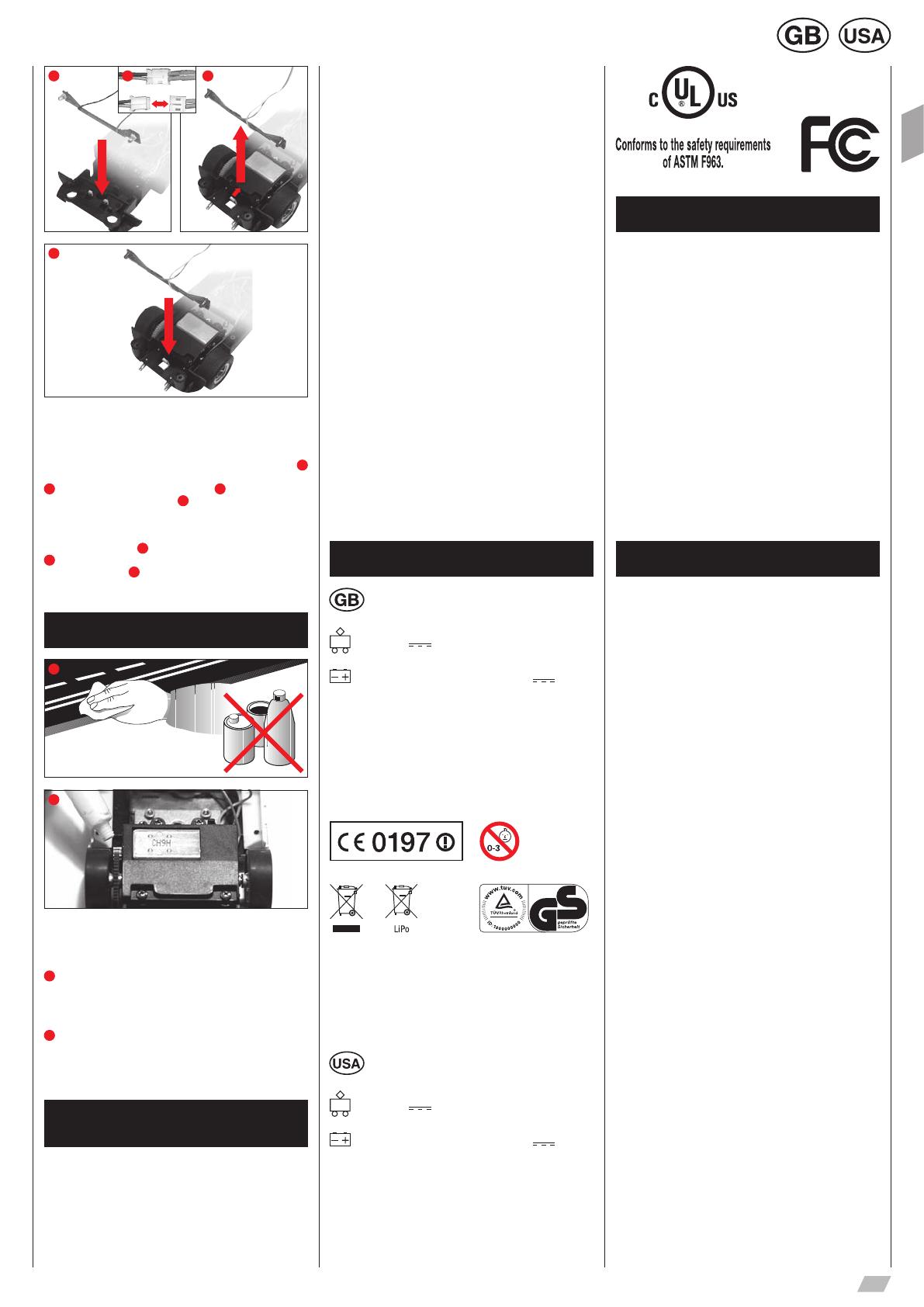
ATTENTION! Depending on the model, the light boards might be
screwed tight.
Front light: To change the light boards unscrew the car’s upper
part from the chassis. Unscrew the front axle according to fig.
1
and remove the cables between the front light and the car board (fig.
2
). Slightly bend down the catch hook (fig.
3
) and pull up the light
board. Insert the light board (fig.
4
), until the catch hook latches
in. Screw in the front axle and fit the cables together according to
their colours.
Rear light: Remove the cables between the rear light and the car
board according to fig.
5
Slightly bend down the catch hook (fig.
6
) and pull up the light board. Insert the light board until the catch
hook latches in (fig.
7
) and fit the cables together according to
their colours.
Maintenance and care
1
2
To ensure a proper operation of the motor-racing circuit, all race-
track components should be regularly cleaned. Pull the plug prior to
cleaning.
1
Racetrack: Keep the track surface and track slots clean with a
dry cloth. Do not use any solvents or chemicals for cleaning. When
it is not in use, store the racetrack in a clean and dust-protected
location, preferably in the original cardboard box.
2
Car check: Clean axle and wheel bearings, pinion gears, gear-
wheels and bearings and lubricate using a resin- and acid-free
grease. You can use a toothpick or similar as aid. Regularly check
the condition of sliding contacts and tyres..
Troubleshooting
Driving tips
Troubleshooting:
In case of any malfunctions, please check the following:
Has the connection to the power supply been established cor-
rectly?
Have transformer and speed controllers been connected correctly?
Are the track connections faultless?
Are the racetrack and track slots clean and free of any foreign
objects?
Are the sliding contacts in order and do they make contact with
the track slot?
Are the cars correctly coded to the according speed controller?
The track‘s current feed will be switched off automatically for 5
seconds, if there is an electrical short circuit: this will be notified by
audible and visual signals.
Are the cars placed on the track in running direction? In case of
non-functioning push the running direction switch which is on the
car´s bottom.
Is the adapter unit correctly installed facing the direction of travel?
Is the speed controller battery properly connected?
Is the battery fully charged?
Does the LED on the controller flash while charging?
Is the speed controller bound to the receiver?
Has the speed controller got a duplicate address assignment?
Note:
During operation small car parts as spoilers or mirrors may get off or
brake due to being original detailed parts of the car model. To avoid
this it is possible to remove them before operation.
Driving technique:
You can drive fast along the straight track but you should brake
before the curve and then accelerate again when coming out of the
curve.
Do not fasten or block the vehicles when the motor is running:
overheating or damage to the motor could result otherwise.
Note: When using track systems which are not manufactured by
Carrera the existing guide keel has to be replaced by the special
guide keel (#85309). While using the Carrera crossing (#20587) or
high banked curve 1/30° (#20574) slight driving noise might occur
which is due to the full-scale genuineness and does not affect flaw-
less operation.
All Carrera spare parts are available in the webshop:
carrera-toys.com
Delivery exclusively to Germany, Austria, Netherlands, Belgium and
Luxembourg.
Technical specifications
Output voltage: Toy transformer
18 V 54 VA
Lithium polymer rechargeable battery: 3,7 150mAh
Electricity modes:
1.) Operating mode = cars are operated via speed controllers
2.) Idle mode = speed controllers not activated, no game
3.) Stand-by mode = after approx. 20 minutes idle mode the
connecting section switches to stand-by mode. LED flashes at
long intervals. CURRENT CONSUMPTION < 0.5 watt / 0.5w
By operating the speed controller the stand-by mode is finished,
the racetrack returns to idle-mode again.
4.) Off-state = power supply unit disconnected from mains supply
This device is marked by “selective sort throught” symbol related to
sort through domestic, electric and electronic, waste. This means
the product must be treated by a specialized “sorting/collecting” sys-
tem in accordance with European directive 2002/96/CE, to reduce
the impact upon environment. For more precise information, please
contact your local administration. Electronical product which are
not going through special collecting, are potentially dangerous for
environment and human health, because of dangerous substance.
Output voltage: Toy transformer
18 V 54 VA
Lithium polymer rechargeable battery: 3,7 150mAh
Electricity modes:
1.) Operating mode = cars are operated via speed controllers
2.) Idle mode = speed controllers not activated, no game
3.) Stand-by mode = after approx. 20 minutes idle mode the
connecting section switches to stand-by mode. LED flashes at
long intervals. CURRENT CONSUMPTION < 1 watt / 1w
By operating the speed controller the stand-by mode is finished,
the racetrack returns to idle-mode again.
4.) Off-state = power supply unit disconnected from mains supply
Requirement for FCC Part 15
Warning: Changes or modifications not expressly approved
by the party responsible for compliance could void the user’s
authority to operate the equipment.
Note: This equipment has been tested and found to comply with the
limits for a Class B digital device, pursuant to Part 15 of the FCC
Rules. These limits are designed to provide reasonable protection
against harmful interference in a residential installation.
This equipment generates, uses and can radiate radio frequency
energy and, if not installed and used in accordance with the instruc-
tions, may cause harmful interference to radio communications.
However, there is no guarantee that interference will not occur in
a particular installation.
If this equipment does cause harmful interference to radio or televi-
sion reception, which can be determined by turning the equipment
off and on, the user is encouraged to try to correct the interference
by one or more of the following measures:
Reorient or relocate the receiving antenna.
Increase the separation between the equipment and receiver,
Connect the equipment into an outlet on a circuit different
from that to which the receiver is connected.
Consult the dealer or an experienced radio/TV technician for
help.
Warnings
Guidelines and warnings about using the LiPo battery/
batteries:
LiPo rechargeable batteries are much more sensitive than the
traditional alkaline or NiMh rechargeables. For this reason all in-
structions and warnings must be scrupulously observed. Incorrect
treatment of LiPo rechargeable batteries may cause a fire. In han-
dling, charging and using the LiPo battery/batteries supplied, you
take over all responsibility for the risks attached to lithium batteries.
Non-rechargeable batteries must not be recharged!
For recharging batteries, only the charging cradle supplied may be
used. If this instruction is disregarded, there is a risk of fire which
may endanger your health and/or cause damage to property.
NEVER use any other charging unit!
Rechargeable batteries may only be recharged under adult super-
vision. When charging, never leave the battery unattended.
When you recharge the battery, you should always be in the vicinity
to keep watch on the process so that you can react to any possible
problem.
If the battery swells or deforms during either discharge or charging
process, stop the process immediately. Remove the battery as fast
and as carefully as possible and place it on a safe and open area
away from any flammable materials, and keep it under observation
for at least 15 minutes. If you continue to charge or discharge a bat-
tery which has already started to swell or deform, there is danger of
fire! Even at the slightest sign of swelling or deforming, the battery
must be taken out of service.
The battery supplied must be charged in a safe place away from
flammable materials.
Store the battery at room temperature (16 - 18 °C) in a dry place.
Do not expose the battery to direct sunlight or any other sources of
heat. Temperatures over 50 °C are generally to be avoided.
Always recharge the battery after use to avoid the possibility of its
becoming deep discharged. When it is not in use, recharge the bat-
tery from time to time, say every 2-3 months. Failure to observe the
methods of handling described above may lead to defects.
When changing batteries do not use any sharp or pointed objects
or tools. Avoid damaging the protective foil around the battery at
all costs.
When replacing defective batteries, only the recommended battery
types may be used. Damaged or unusable batteries are hazardous
waste, and must be disposed of accordingly.
Never throw batteries, rechargeable or otherwise, on the fire or
expose them to high temperatures. This may cause a fire or an
explosion.
The electrolyte and electrolyte vapour in the LiPo batteries are
hazardous to health. Always avoid direct contact with electrolyte.
If electrolyte makes contact with skin, eyes or other parts of the
body, it must immediately be washed out or off with plenty of fresh
water and a doctor must be consulted.
Rechargeable batteries are not toys and must not fall into the
hands of children. Keep batteries inaccessible to children.
The connector clips / battery connections must never be short-
circuited!
The toy is only to be operated with a transformer or power pack
designed for use with toys!
The transformer / the power pack is not a toy!
  • Page 1 1
  • Page 2 2
  • Page 3 3
  • Page 4 4
  • Page 5 5
  • Page 6 6
  • Page 7 7
  • Page 8 8
  • Page 9 9
  • Page 10 10
  • Page 11 11
  • Page 12 12
  • Page 13 13
  • Page 14 14
  • Page 15 15
  • Page 16 16
  • Page 17 17
  • Page 18 18
  • Page 19 19
  • Page 20 20
  • Page 21 21
  • Page 22 22
  • Page 23 23
  • Page 24 24
  • Page 25 25
  • Page 26 26

Carrera 23613 GENTLEMEN RACE Owner's manual

Category
Toy vehicles
Type
Owner's manual
This manual is also suitable for

Ask a question and I''ll find the answer in the document

Finding information in a document is now easier with AI