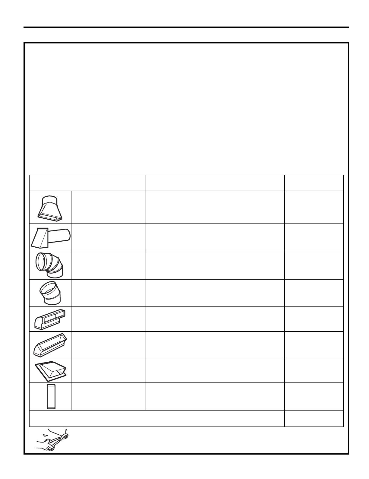
EQUIVALENT NUMBER EQUIVALENT
DUCT PIECES LENGTH x USED = LENGTH
Rectangular-to-Round 5 Ft. (1.5 m) x ( ) = Ft. or m
Transition Adaptor*
Wall Cap 40 Ft. (12.2 m) x ( ) = Ft. or m
90° Elbow 10 Ft. (3 m) x ( ) = Ft. or m
45° Elbow 5 Ft. (1.5 m) x ( ) = Ft. or m
90° Elbow 25 Ft. (7.6 m) x ( ) = Ft. or m
45° Elbow 5 Ft. (1.5 m) x ( ) = Ft. or m
Roof Cap 24 Ft. (7.3 m) x ( ) = Ft. or m
Straight Duct 6“ (15.2 cm) 1 Ft. (0.3 m) x ( ) = Ft. or m
Round or 3
1
⁄4“ x 10“
(8.2 x 25.4 cm Rectangular)
Total Ductwork = Ft. or m
Equivalent lengths of duct pieces are based on actual tests
and reflect requirements for good venting performance with
any vent hood.
* IMPORTANT: If a rectangular-to-round transition
adaptor is used, the bottom corners of the damper
will have to be cut to fit, using the tin snips, in order
to allow free movement of the damper
.
NOTE: If you need to install ducts, note that the total
duct length of 3
1
⁄4” x 10” (8.2 x 25.4 cm) rectangular or
” (15.2 cm) diameter round duct
Outside ventilation requires an EXTERNAL EXHAUST
NOTE: It is important that venting be installed using
the most direct route and with as few elbows as possible.
This ensures clear venting of exhaust and helps prevent
blockages. Also, make sure dampers swing freely and
nothing is blocking the ducts.
Exhaust connection:
The exhaust adaptor has been designed to mate with
a standard 3
1
⁄4” x 10” (8.2 x 25.4 cm) rectangular duct.
If a round duct is required, a rectangular-to-round
Maximum duct length:
For satisfactory air movement, the total duct length of
3
1
⁄4” x 10” (8.2 x 25.4 cm) rectangular or
6”(15.2 cm)
diameter round duct should not
exceed 120 equivalent
feet (36.5 m).
Elbows, transitions, wall and roof caps,
etc.,
present additional resistance to airflow and are
equivalent to a section of straight duct which is longer
than their actual physical size. When calculating the total
duct length, add the equivalent lengths of all transitions
and adaptors plus the length of all straight duct sections.
The chart below shows you how to calculate total
equivalent ductwork length using the approximate feet
of equivalent length of some typical ducts.
Installation Instructions
INSTALLATION INSTRUCTIONS FOR EXTERNAL EXHAUST DUCTING
DUCT.Read the following carefully.
(12.5”
should not exceed 120 equivalent feet (36.5 m).
diameter/ 6
(12.5”
diameter/
7 cm)
7 cm)
transition adaptor must be used.
diameter duct is acceptable to use.
"
A 5"""''''' " (12.7cm)/ 6" (15.2cm)
"