Simer Pumps 2.81E+01 User manual
- Category
- Water pumps
- Type
- User manual
This manual is also suitable for

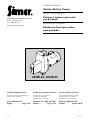
OWNER’S MANUAL
Shallow Well Jet Pumps
NOTICE D’UTILISATION
Pompes à éjecteur pour puits
peuprofonds
MANUAL DEL USUARIO
Bombas de chorro para pozos
poco profundos
293 Wright Street, Delavan, WI 53115
Phone: 1-800-468-7867
Fax: 1-800-390-5351
Web Site: SimerPump.com
Installation/Operation/Parts
For further operating, installation, or
maintenance assistance:
Call 1-800-468-7867
English. . . . . . . . . . . Pages 2-10
Installation/Fonctionnement/Pièces
Pour plus de renseignements
concernant l’utilisation,
l’installation ou l’entretien,
Composer le 1 (800) 468-7867
Français. . . . . . . . . Pages 11-19
Instalación/Operación/Piezas
Para mayor información sobre el
funcionamiento, instalación o
mantenimiento de la bomba:
Llame al 1-800-468-7867
Español . . . . . . . Paginas 20-28
© 2011 SIM929 (4/7/11)
2805E-02, 2810E-02

Important Safety Instructions
SAVE THESE INSTRUCTIONS - This manual contains
important instructions that should be followed during
installation, operation, and maintenance of the product.
Save this manual for future reference.
This is the safety alert symbol. When you see this
symbol on your pump or in this manual, look for one of
the following signal words and be alert to the potential
for personal injury!
indicates a hazard which, if not avoided, will
result in death or serious injury.
indicates a hazard which, if not avoided,
could result in death or serious injury.
indicates a hazard which, if not avoided,
could result in minor or moderate injury.
NOTICE
addresses practices not related to personal injury.
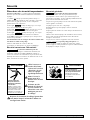
Carefully read and follow all safety instructions in this
manual and on pump.
Keep safety labels in good condition.
Replace missing or damaged safety labels.
Electrical Safety
Capacitor voltage may be hazardous.
To discharge motor capacitor, hold insulated handle
screwdriver BY THE HANDLE and short capacitor
terminals together. Do not touch metal screwdriver blade
or capacitor terminals. If in doubt, consult a qualified
electrician.
General Safety
Do not touch an operating motor. Modern
motors are designed to operate at high temperatures. To
avoid burns when servicing pump, allow it to cool for
20minutes after shut-down before handling.
Do not allow pump or any system component to freeze.
To do so will void warranty.
Pump water only with this pump.
Periodically inspect pump and system components.
Wear safety glasses at all times when working on pumps.
Keep work area clean, uncluttered and properly lighted;
store properly all unused tools and equipment.
Keep visitors at a safe distance from the work areas.
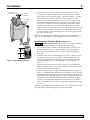
Pump body may explode if used as a
booster pump unless relief valve capable of passing full
pump flow at 75 psi is installed.
Safety 2
For parts or assistance, call Simer Customer Service at 1-800-468-7867
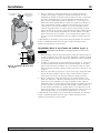
WARNING
Hazardous pressure!
Install pressure relief
valve in discharge pipe.
Release all pressure on
system before working on
any component.
WARNING
Hazardous voltage.
Can shock, burn, or
cause death.
Ground pump before
connecting to power
supply. Disconnect power
before working on pump,
motor or tank.
Wire motor for correct
voltage. See “Electrical”
section of this manual
and motor nameplate.
Ground motor before
connecting to power
supply.
Meet National Electrical
Code, Canadian
Electrical Code, and
local codes for all
wiring.
Follow wiring
instructions in this
manual when
connecting motor to
power lines.

Warranty 3
Retain Original Receipt For Your Records
Limited Warranty
SIMER warrants to the original consumer purchaser (“Purchaser” or “You”) of its products that they are free from defects in material and workmanship
for a period of twelve (12) months from the date of the original consumer purchase.
If, within twelve (12) months from the original consumer purchase, any such product shall prove to be defective, it shall be repaired or replaced at
SIMER’s option, subject to the terms and conditions set forth below. The original purchase receipt and product warranty information label are required
to determine warranty eligibility. Eligibility is based on purchase date of original product – not the date of replacement under warranty. The warranty is
limited to repair or replacement of product only – Purchaser pays all removal, installation, labor, shipping, and incidental charges.
For parts or troubleshooting assistance, DO NOT return product to your retail store. Contact SIMER Customer Service at 1-800-468-7867.
Claims made under this warranty shall be made by returning the product (except sewage pumps, see below) to the retail outlet where it was purchased
immediately after the discovery of any alleged defect. SIMER will subsequently take corrective action as promptly as reasonably possible. No requests
for service will be accepted if received more than 30 days after the warranty expires.
Warranty does not apply to products used in commercial/rental applications.
Sewage Pumps
DO NOT return a sewage pump (that has been installed) to your retail store. Contact SIMER Customer Service. Sewage pumps that have seen service
and been removed carry a contamination hazard with them.
If your sewage pump has failed:
• Wearrubbergloveswhenhandlingthepump;
• Forwarrantypurposes,returnthepump’scordtagandoriginalreceiptofpurchasetotheretailstore;
• Disposeofthepumpaccordingtolocaldisposalordinances.
Exceptions to the Twelve (12) Month Limited Warranty
General Terms and Conditions
You must pay all labor and shipping charges necessary to replace product covered by this warranty. This warranty does not apply to the following: (1)
actsofGod;(2)productswhich,inSIMER’ssolejudgement,havebeensubjecttonegligence,abuse,accident,misapplication,tampering,oralteration;
(3)failuresduetoimproperinstallation,operation,maintenanceorstorage;(4)atypicalorunapprovedapplication,useorservice;(5)failurescaused
by corrosion, rust or other foreign materials in the system, or operation at pressures in excess of recommended maximums.
This warranty sets forth SIMER’s sole obligation and purchaser’s exclusive remedy for defective products.
SIMER SHALL NOT BE LIABLE FOR ANY CONSEQUENTIAL, INCIDENTAL, OR CONTINGENT DAMAGES WHATSOEVER.
THE FOREGOING WARRANTIES ARE EXCLUSIVE AND IN LIEU OF ALL OTHER EXPRESS AND IMPLIED WARRANTIES, INCLUDING BUT NOT LIMITED
TO THE IMPLIED WARRANTIES OF MERCHANTABILITY AND FITNESS FOR A PARTICULAR PURPOSE. THE FOREGOING WARRANTIES SHALL NOT
EXTEND BEYOND THE DURATION PROVIDED HEREIN.
Some states do not allow the exclusion or limitation of incidental or consequential damages or limitations on how long an implied warranty lasts, so
the above limitations or exclusions may not apply to You. This warranty gives You specific legal rights and You may also have other rights which vary
from state to state.
SIMER • 293 Wright Street • Delavan, WI U.S.A. 53115
Phone: 1-800-468-7867 • Fax: 1-800-390-5351 • Web Site: simerpump.com
Product Warranty Period
BW85P,CM10,CMK,M40,M40P 90 days
2300,2310,2330,2520ULST,2943,2955,2956,2957,2960,5023SS,A5500 2 Years
4”SubmersibleWellPumps,2945,2958,2975PC,2985,3075SS,3983,3984 3 Years
Pre-ChargeWaterSystemTank,3985,3986,3988,3989 5Years
3963,3995,3997 Lifetime

Installation 4
For parts or assistance, call Simer Customer Service at 1-800-468-7867
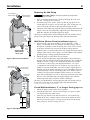
Replacing An Old Pump
Hazardous voltage. Disconnect power to pump before
working on pump or motor.
1. Drain and remove the old pump. Check the old pipe for scale, lime,
rust, etc., and replace it if necessary.
2. Install the pump in the system. Make sure that all pipe joints in the
suction pipe are air-tight as well as water tight. If the suction pipe can
suck air, the pump will not be able to pull water from the well.
3. Adjust the pump mounting height so that the plumbing connections do
not put a strain on the pump body. Support the pipe so that the pump
body does not take the weight of piping or fittings.
You have just completed the well plumbing for your new shallow well jet
pump. Please go to Page 6 for discharge pipe and tank connections.
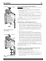
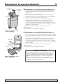
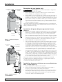
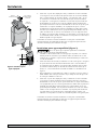
Well Point (Driven Point) Installation (Figure 1)
1. Drive the well, using “drive couplings” and a “drive cap”. “Drive
fittings” are threaded all the way through and allow the pipe ends to
butt against each other so that the driving force of the maul is carried
by the pipe and not by the threads. The ordinary fittings found in
hardware stores are not threaded all the way through the fitting and can
collapse under impact. “Drive fittings” are also smoother than standard
plumbing fittings, making ground penetration easier.
2. Mount the pump as close to the well as possible.
3. Use the fewest possible fittings (especially elbows) when connecting
the pipe from the well point to the pump suction port. The suction pipe
should be at least as large as the suction port on the pump (include
a check valve if your pump is not equipped with one – see Figure
1). Support the pipe so that there are no dips or sags in the pipe, so
it doesn’t strain the pump body, and so that it slopes slightly upward
from the well to the pump (high spots can cause air pockets which can
air lock the pump). Seal the suction pipe joints with
1
Teflon™ tape or
a Teflon™ based pipe joint compound. Joints must be air- and water-
tight. If the suction pipe can suck air, the pump cannot pull water from
the well. If one well point does not supply enough water, consider
connecting two or three well points to one suction pipe.
You have just completed the suction piping for your new shallow well jet
pump. Please go to Page 6 for discharge pipe and tank connections.
1
E. I. DuPont de Demours and Company Corporation, Delware
Cased Well Installation, 2” or Larger Casing (Figure2)
1. Mount the pump as close to the well as possible.
2. Assemble the foot valve, strainer, and well pipe (see Figure 2). Make
sure that the foot valve works freely.
3. Lower the pipe into the well until the strainer is five feet above the
bottom of the well. It should also be at least 10 feet below the well’s
water level while the pump is running in order to prevent the pump
from sucking air. Install a sanitary well seal.
To Household
Water System
Pump Priming
Tee and Plug
ca e
Drive
Coupling
Drive
Point
Priming
Tee and
Plug
Drive point
below water
level
Check
Valve
To Household
Water System
Pump Priming
Tee and Plug
10'
Min.
5–10'
Suction Pipe
From Well
Foot
Valve
Priming
Tee and
Plug
Sanitary
Well Seal
Figure 1: Driven Point Installation
Figure 2: Cased Well Installation
Typical pump
shown herein
not to scale

Installation 5
For parts or assistance, call Simer Customer Service at 1-800-468-7867
4. Install a priming tee, priming plug, and suction pipe to the pump
(see Figure 2). Connect the pipe from the well to the pump suction
port, using the fewest possible fittings – especially elbows – as fittings
increase friction in the pipe (however, include a foot valve – see
Figure2). The suction pipe should be at least as large as the suction
port on the pump. Support the pipe so that there are no dips or sags
in the pipe, so it doesn’t strain the pump body, and so that it slopes
slightly upward from the well to the pump (high spots can cause air
pockets which can air lock the pump). Seal the suction pipe joints with
Teflon™ tape or a Teflon™ based pipe joint compound. Joints must be
air- and water-tight. If the suction pipe can suck air, the pump cannot
pull water from the well.
You have just completed the suction piping for your new shallow well jet
pump. Please go to Page 6 for discharge pipe and tank connections.
Installation for Surface Water (Figure 3)
Possible contamination. Do not use surface water for drinking.
The installation shown could be used for sprinkler applications.
1. The pump should be installed as close to the water as possible, with
the fewest possible fittings (especially elbows) in the suction pipe.
The suction pipe should be at least as large as the suction port on
thepump.
2. Assemble a foot valve and suction pipe (see Figure 3). Make sure that
the foot valve works freely. Use Teflon™ tape or a Teflon™-based
pipe joint compound on threaded pipe joints. Protect the foot valve
assembly from fish, trash, etc, by installing a screen around it (see
Figure 3).
3. Lower the pipe into the water until the strainer is five feet above the
bottom. It should also be at least 10 feet below the water level in order
to prevent the pump from sucking air.
4. Install a priming tee, priming plug, and suction pipe to the pump (see
Figure 3). Support the pipe so that there are no dips or sags in the pipe,
so it doesn’t strain the pump body, and so that it slopes slightly upward
from the well to the pump (high spots can cause air pockets which can
air lock the pump). Seal the suction pipe joints with Teflon™ tape or
a Teflon™ based pipe joint compound. Joints must be air- and water-
tight. If the suction pipe can suck air, the pump cannot pull water from
thewell.
You have just completed the plumbing for your new shallow well jet pump.
Please go to Page 6 for discharge pipe and tank connections.
Suction Pipe
From Well
10'
Min.
5–10'
Foot
Valve
Screen
To Household
Water System
Pump Priming
Tee and Plug
Figure 3: Surface Water Installation

Discharge Pipe and Pressure Tank Connections 6
For parts or assistance, call Simer Customer Service at 1-800-468-7867
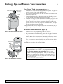
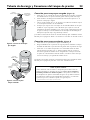
Pre-Charge Tank Connection (Figure 4)
1. Install two tees in the pump discharge port (see Figure 4). The pipe size
must be at least as large as the discharge port.
2. Run a pipe or reinforced hose from one arm of the first tee to the port
on the pre-charged tank.
3. Connect the other end of the discharge tee to your plumbing system.
Cap the tee with a threaded plug or a pressure gauge.
4. Check the pre-charge of air in the tank with an ordinary tire gauge. The
pre-charge should be 2 PSI less than the cut-in setting of the pump’s
pressure switch. The pre-charge is measured when there is no water
pressure in the tank. Your new pump has a 30/50 PSI switch, so adjust
the tank pre-charge pressure to 28 PSI.
Congratulations! You have just completed the tank connection for your jet
pump. Please go to Page 7 for electrical hookup.
Standard Tank Connection (Figure 5)
1. Install one tee in the pump discharge port (see Figure 5).
2. Run a pipe from the pump discharge port to the inlet port of your tank.
The pipe size must be at least as large as the discharge port.
3. Install a tee in the suction pipe near the pump. Install a reducer
bushing down to 1/8” NPT in the tee. Run tubing from the tee to the
port on the AVC mounted on the tank. Seal all joints with Teflon™
tape. See instructions provided with the tank and the AVC for details.
Congratulations! You have just completed the tank connection for your jet
pump. Please go to Page 7 for electrical hookup.
From
Well
To Household
Water System
Pump Priming
Tee and Plug
Pressure
Switch
To Household
Water System
Pressure
Switch
From
Well
Air Volume
Control
Air Volume
Control Tube
Pump
Priming Tee
and Plug
Figure 4: Pre-charged Tank Connections
Figure 5: Standard Tank Connections
Sealing Pipe Joints
Use only
1
Teflon™ tape or Teflon™ based joint compounds for
making all threaded connections to the pump itself. Do not
use pipe joint compounds on plastic pumps: they can react
with the plastic in pump components. Make sure that all pipe
joints in the suction pipe are air tight as well as water tight. If
the suction pipe can suck air, the pump will not be able to pull
water from the well.
1
E. I. DuPont de Demours and Company Corporation, Delware

For parts or assistance, call Simer Customer Service at 1-800-468-7867
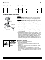
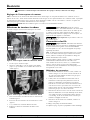
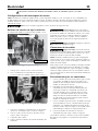
Dial Type Voltage Selector
Voltage is set to 230 volts. To change to 115 volts:
1. Make sure power is off.
2. Turn the dial counter-clockwise until 115 shows in
the dial window as shown in Figure 7.
3. Attach the incoming power leads to the two outer
screws on the pressure switch as shown in Figure 6.
4. Attach the ground wire to the grounding connections
as shown in Figure 6.
5. If there are other wires, they should be capped.
6. Reinstall the pressure switch and motor end covers.
Hazardous voltage. Can shock, burn, or
kill. Connect ground wire before connecting power
supply wires. Use the wire size (including the ground
wire) specified in the wiring chart. If possible, connect
the pump to a separate branch circuit with no other
appliances on it.
Explosion hazard. Do not ground to a gas
supply line.
Wiring Connections
Fire hazard. Incorrect voltage can cause
a fire or seriously damage the motor and voids the
warranty. The supply voltage must be within ±10% of the
motor nameplate voltage.
NOTICE: Dual-voltage motors may be set for 115V
or 230V. If necessary, reset the motor to the desired
voltage, as shown. Do not alter the wiring in single
voltagemotors.
Install, ground, wire, and maintain your pump in
compliance with the National Electrical Code (NEC) or
the Canadian Electrical Code (CEC), as applicable, and
with all local codes and ordinances that apply. Consult
your local building inspector for code information.
Connection Procedure:
1. Connect the ground wire first as shown in Figure 6.
The ground wire must be a solid copper wire at least
as large as the power supply wires.
2. There must be a solid metal connection between the
pressure switch and the motor for motor grounding
protection. If the pressure switch is not connected
to the motor, connect the green ground screw in the
switch to the green ground screw under the motor
end cover. Use a solid copper wire at least as large
as the power supply wires.
3. Connect the ground wire to a grounded lead in a
service panel, to a metal underground water pipe, to
a metal well casing at least ten feet (3m) long, or to
a ground electrode provided by the power company
or the hydro authority.
4. Connect the power supply wires to the pressure
switch as shown in Figure 6.
You have just completed the wiring for your pump.
Please go to Page 8 for startup preparations.
Figure 6: Voltage set to 230 volts, Dial Type
Ground Wire Connection
Power Supply Connections
Voltage
Change
Dial
Pressure Switch
Figure 7: Voltage set to 115 volts, Dial Type
Electrical 7
Disconnect power before working on pump, motor, pressure switch, or wiring.
Motor Switch Settings
NOTICE: 1/2 HP motors are dual voltage and are factory set to 115V. 3/4 & 1 HP motors are also dual voltage, but are
factory set to 230V. Motor terminal board (located under the motor end cover) should look like that shown below. Use
the instructions to set your motor to match your power source.
Never connect a motor set to 115V to a 230V power source.

Electrical 8
For parts or assistance, call Simer Customer Service at 1-800-468-7867
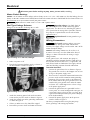
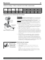
Fill pump
and piping
through
priming tee.
Can fill downpipe
separately through
2nd priming tee.
Priming
Explosion hazard. Never run pump against closed discharge.
To do so can boil water inside pump, causing hazardous pressure in unit,
risk of explosion and possibly scalding persons handling pump.
Never run pump dry. Running pump without water may cause
pump to overheat, damaging seal and possibly causing burns to persons
handling pump. Fill pump with water before starting.
1. Remove the priming plug from the pump and fill the pump, fill all
piping between the pump and the well, and make sure that all piping
in the well is full. If you have also installed a priming tee in the suction
piping, remove the plug from the tee and fill the suction piping.
2. Replace all fill plugs.
3. Power on! Start the pump. If you don’t have water after 2 or 3 minutes,
stop the pump and remove the fill plugs. Refill the pump and piping.
You may have to repeat this several times in order to get all the trapped
air out of the piping. A pump lifting water 25’ may take as long as
15minutes to prime.
4. After the pump has built up pressure in the system and shut off, check
the pressure switch operation by opening a faucet or two and running
enough water out to bleed off pressure until the pump starts. The pump
should start when pressure drops to 30 PSI and stop when pressure
reaches 50 PSI. Run the pump through one or two complete cycles to
verify correct operation. This will also help clean the system of dirt and
scale dislodged during installation.
Winterizing the Pump
To prepare the pump for freezing temperatures:
1. Shut off power to the pump.
2. Relieve system pressure. Open a faucet and let it drain until water
stops flowing.
3. Drain the pump. Your pump may have a separate drain plug. Remove
this plug and let it drain.
Your pump may only have a plug or connection on the side of the
pump. Remove this and let the pump drain. Some water will remain in
the pump. A small amount of water left in the pump will not harm it if
it freezes.
Figure 8: Prime the Pump
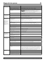
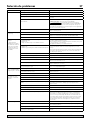
Model Motor HP Volts
Max. Load
Amp
Branch Fuse
Rating Amp
DISTANCE IN FEET FROM MOTOR TO SUPPLY
0 - 100 101 - 200 201 - 300 301 - 400 401 - 500
AWG WIRE SIZE (mm
2
)
2805E-02 1/2 115/230 9.9/4.95 15/15 14/14(2/2) 14/14(2/2) 12/14(3/2) 10/14(5.5/2) 10/12(5.5/3)
2810E-02 3/4 115/230 12.4/6.2 20/15 12/14(3/2) 10/14(5.5/2) 8/14(8.4/2) 6/12(14/3) 6/12(14/3)
Wiring Chart – Recommended Wire and Fuse Sizes
Preparing to Start the Pump

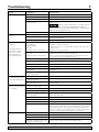
Symptom Possible Cause(s) Corrective Action
Motor will not run Disconnect switch is off Be sure switch is on.
Fuse is blown or circuit breaker tripped Replace fuse or reset circuit breaker.
Starting switch is defective DISCONNECT POWER; Replace starting switch.
Wires at motor are loose, disconnected, or
wired incorrectly
Refer to instructions on wiring (Page 9). DISCONNECT POWER; check and
tighten all wiring.
Capacitor voltage may be hazardous. To discharge capacitor,
hold insulated handle screwdriver BY THE HANDLE and short capacitor
terminals together. Do not touch metal screwdriver blade or capacitor terminals.
If in doubt, consult a qualified electrician.
Pressure switch contacts are dirty DISCONNECT POWER and file contacts with emery board or nail file.
Motor runs hot and overload
kicks off
Motor is wired incorrectly Refer to instructions on wiring.
Voltage is too low Check with power company. Install heavier wiring if wire size is too small (See
Electrical / Wiring Chart).
Pump cycles too frequently See section below on too frequent cycling.
Motor runs but no water is
delivered*
Pump in new installation did not pick up
prime through:
1. Improper priming
2. Air leaks
3. Leaking foot valve or check valve
In new installation:
1. Re-prime according to instructions.
2. Check all connections on suction line, AVC, and ejector with soapy water or
shaving cream.
3. Replace foot valve or check valve.
Pump has lost prime through:
1. Air leaks
2. Water level below suction pipe inlet
In installation already in use:
1. Check all connections on suction line and shaft seal.
2. Lower suction line into water and re-prime. If receding water level in well
exceeds 25’ (7.6M), a deep well pump is needed.
Foot valve or strainer is plugged Clean foot valve or strainer.
Ejector or impeller is plugged Clean ejector or impeller.
Check valve or foot valve is stuck shut Replace check valve or foot valve.
Pipes are frozen Thaw pipes. Bury pipes below frost line. Heat pit or pump house.
Foot valve and/or strainer are buried in
sand or mud
Raise foot valve and/or strainer above bottom of water source. Clean foot valve
and strainer.
Water level is too low for shallow well
setup to deliver water
A deep well jet will be needed if your well is more than 25’ (7.6M) depth to
water.
Pump does not deliver water
to full capacity (Also check
point 3 immediately above)
Water level in well is lower than estimated A new nozzle and venturi combination may be needed.
Steel piping (if used) is corroded or limed,
causing excess friction
Replace with plastic pipe where possible, otherwise with new steel pipe.
Piping is too small in size Use larger piping.
Pump delivers water but does
not shut off or pump cycles
too frequently
Pressure switch is out of adjustment or
contacts are welded together
DISCONNECT POWER; adjust or replace pressure switch.
Faucets have been left open Close faucets.
Venturi, nozzle or impeller is clogged Clean venturi, nozzle or impeller.
Standard pressure tank is waterlogged and
has no air cushion
Drain tank to air volume control port. Check AVC for defects. Check all
connections for air leaks.
Pipes leak Check connections.
Foot valve leaks Replace foot valve.
Pressure switch is out of adjustment Adjust or replace pressure switch.
Air charge too low in pre-charged tank
DISCONNECT POWER and open faucets until all pressure is relieved. Using
tire pressure gauge, check air pressure in tank at valve stem located on the tank.
If less than pressure switch cut-in setting (30-50 PSI), pump air into tank from
outside source until air pressure is 2 PSI less than cut-in setting of switch. Check
air valve for leaks (use soapy solution) and replace core if necessary.
Air spurts from faucets Pump is picking up prime When pump has picked up prime, it should pump solid water with no air.
Leak in suction side of pump Suction pipe is sucking air. Check joints for leaks with soapy water.
Well is gaseous Consult factory about installing a sleeve in the well.
Intermittent over-pumping of well. (Water
drawn down below foot valve.)
Lower foot valve if possible, otherwise restrict pump discharge.
Troubleshooting 9
* Stop pump; then check
prime before looking for
other causes. Unscrew
priming plug and see if
water is in priming hole.
For parts or assistance, call Simer Customer Service at 1-800-468-7867

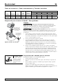
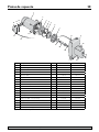
Repair Parts 10
For parts or assistance, call Simer Customer Service at 1-800-468-7867
1
2
3
4
5
6
7
8
9A
11
9
10
10
10
9B
16
13
12
17
14
15
2331 0296
Item Description Qty. 2810E-02 2805E-02
1 Motor (-L) 1 J218-590PKG J218-582A-115PKG
2 Water Slinger 1 17351-0009 17351-0009
3 Seal Plate Assembly 1 N3-9 N3-9
4 Gasket, Seal Plate 1 N20-35 N20-35
5 Shaft Seal 1 U109-6A U109-6A
6 Impeller 1 J105-42P J105-40P
7 Volute Diffuser 1 L1-25P L1-25P
8 Gasket, Diffuser 1 N20-34 N20-34
9 Pump Body Assembly 1 N176-38F N176-38
9A Venturi (1) N32P-75 N32P-66
9B Nozzle (1) N34P-21 (#47) N34P-17 (#43)
10 Pipe Plug, 1/4” NPT Hex Hd. 3 § §
11 Barbed Fitting, 1/4” NPT 1 U111-211T U111-211T
12 Barbed Elbow, 1/4” NPT 1 U111-212T –
13 Tube, 1/4”x14-1/2” 1 U37-672P U37-672P
14 Pressure Switch 1 U217-1202 U217-1202
15 Locknut, 1/2” 1 U36-112ZP U36-112ZP
16 Connector 1 L43-5C L43-5C
17 Capscrew 3/8-16x1-1/4” Lg. Hex Hd. 4 § §
§ Standard hardware item; purchase locally.
Page is loading ...
Page is loading ...
Page is loading ...
Page is loading ...
Page is loading ...
Page is loading ...
Page is loading ...
Page is loading ...
Page is loading ...
Page is loading ...
Page is loading ...
Page is loading ...
Page is loading ...
Page is loading ...
Page is loading ...
Page is loading ...
Page is loading ...
Page is loading ...
-
 1
1
-
 2
2
-
 3
3
-
 4
4
-
 5
5
-
 6
6
-
 7
7
-
 8
8
-
 9
9
-
 10
10
-
 11
11
-
 12
12
-
 13
13
-
 14
14
-
 15
15
-
 16
16
-
 17
17
-
 18
18
-
 19
19
-
 20
20
-
 21
21
-
 22
22
-
 23
23
-
 24
24
-
 25
25
-
 26
26
-
 27
27
-
 28
28


Simer Pumps 2.81E+01 User manual
- Category
- Water pumps
- Type
- User manual
- This manual is also suitable for
Ask a question and I''ll find the answer in the document
Finding information in a document is now easier with AI
in other languages
- français: Simer Pumps 2.81E+01 Manuel utilisateur
- español: Simer Pumps 2.81E+01 Manual de usuario
Related papers
Other documents
-
Simer 3305P Owner's manual
-
Simer 220515H Owner's manual
-
Simer 3110P Owner's manual
-
-
-
-
-
Pentair BW85 Series Owner's manual
-
-