Page is loading ...

United States
qS!
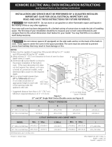
iNSTALLATiONAND SERVICEMUST BEPERFORMEDBYA QUALIFIED INSTALLER.
IMPORTANT: SAVE FOR LOCAL ELECTRICAL INSPECTOR'S USE.
READ AND SAVE THESE INSTRUCTIONS FOR FUTURE REFERENCE.
FOR YOUR SAFETY:Do not store or use gasoilne or other
flammable vapors and liquids in the vicinity of this or any other appliance.
Canada
Your new wall oven has been designed to fit a limited variety of cutout sizes to make the job of installing easier. The
first step of your installation should be to measure your current cutout dimensions and compare them to the cutout
dimensions chart below for your model. You may find little or no cabinet work being necessary.
Do not remove
spacers (if equipped) on the
side walls and/or an the back of
1½" (3.8 crn)
Min.
- o1--
NOTES:
1. Base must be capable of supporting 350 pounds (159 kg).
2. Allow at least 21" (53.3 cm) clearance in front of oven for
door depth when it is open.
3. Dimension G (cutout depth) is critical to the proper
installation of the built-in oven. If the oven decorative
trim does not butt against the cabinet, or if noise is heard
on convection models, verify dimension G to assure it is
according to the required dimension.
Needed (see note 4)
Electrical
Junction Box
Figure 1
_4. For a cutout height (H) between 441/2" (113cm) and
451/8'' (114.6cm) add a 2" (5 cm) ,,vide wood shim of
appropriate height to each side of the opening under the
appliance side rails. Lifting the unit wilt allow you to hide
the cutout openings showing above the unit. The bottom
trim of the unit wilt hide the shims at the bottom.
_'5. For a cutout height (H) between 451/8" (114.6cm) and
467/8" (118.1cm) you can order a larger bottom trim
through your Service Center.
PRO DUCT DIME NSION S
MODEL I A I I C I
27" (68.6 cm) Walt Oven 27 (68.6) 45 9/T6(115.7) 24 5/8 (62.5) 24_/2 (62.2)
30" (76.2cm) Wall Oven 30 (76.2) 45 9/_6(115.7) 28_/4 (71.8) 241/2 (62.2)
f CUTOUT DIMENSIONS AND CABINET WIDTH
27" (68.6cm) Walt Oven 258/8 (65.1)
30" (76.2cm) Walt Oven 281/2(72.4)
All dimensionsare in inches (cm).
Printedin United States
257/8 (65.7)
29 (73.7)
23_/2 (59.7)
23_/2 (59.7)
44_/4 (112.4) 44_/2 (113)
44_/4 (112.4) 44_/2 (113)
27i/8 (68.9) Min
30i/8 (76.5) Min
P/N 318201546 (1011)Rev.A
English- pages 1-6
Espa_ol -paginas 7-12

ImportantNotesto the Installer
1. Read aii instructions contained in these installation
instructions before installing the combination oven.
2. Remove all packing material from the oven compartments
before connecting the electrical supply to the wail oven.
3. Observe all governing codes and ordinances.
4. Be sure to leave these instructions with the consumen
5. Oven door may be removed to facilitate installation.
6. THIS COMBINATION OVEN IS NOT APPROVED
FOR STACKABLE OR SIDE=BY=SIDE INSTALLATION.
Important Note to the Consumer
Keep these instructions with your Owner's Guide for future
reference. Do not discard oven removal tools found in the
literature bag.
IMPORTANT SAFETY
INSTRUCTIONS
* Be sure your combination oven is installed and
grounded properly by a quallfied installer or service
technician.
* This wall oven must be elecfrlcaily grounded in
accordance with local codes or, in their absence,
with the Natlonal Elecfrlcal Code ANSi/NFPA No.70=
latest edition in United Sates, or wlth CSA Standard
C22.1, Canadian Electrlcal Code, Part 1, in Canada.
Stepping, leaning or sitting on the door
of thls wall oven can result in serious injuries and can
also cause damage to the wall oven.
* Never use your wall oven for warming or heating
the room. Prolonged use of the wail oven without
adequate ventilation can be dangerous.
The electrlcal power to the oven must be
shut off while llne connections are being made. Failure
to do so could result in serious injury or death.
1. Carpentry
Refer to figure 1for the dimensions applicable to your
appliance, and the space necessary to receive the
combination oven. The oven support surface may be solid
plywood or similar material, however the surface must be
leveled from side to side and from front to rear.
2. Electrical Requirements
This appliance must be supplied with the proper voltage and
frequency, and connected to an individual, properly grounded
branch circuit, protected by a circuit breaker or fuse. To
know the circuit breaker or fuse required by your model, see
the serial plate to find the wattage consumption and refer to
table A to get the circuit breaker or fuse amperage.
Appliance I I
Protection App !ance Pr0tect_0n
Rating Watt s Circuit Circuit
24OV Recommended Recommended
Lessthan 4800W 20A 20A
4800W - 7200W 30A 30A
7200W - 9600W 40A 40A
9600W and + 50A 50A
Rating Watts
208V
Lessthan 4100W
4100W - 6200W
6200W - 8300W
8300Wand+
TabJe A
Observe all governing codes and local ordinances
I A 3wire or 4wire single phase 120/240 or 120/208 Volt,
60 Hz AC only electrical supply is required on a separate
circuit fused on both sides of the line (red and black wires).
A time-delay fuse or circuit breaker is recommended. DO
NOT fuse neutral (white wire).
NOTE: Wire sizes and connections must conform with the
fuse size and rating of the appliance in accordance with the
American National Electrical Code ANSI/NFPA No. 70-{atest
edition, or with Canadian CSA Standard C22.1, Canadian
Electrical Code, Part 1,and local codes and ordinances.
An extension cord should not be used
wlfh this appliance. Such use may result in a fire,
electrlcal shock, or other personal injury. If you need a
longer power cord you can purchase a 10' (3 m) power cord
kit by calling the Service Center.
.
These appliances should be connected to the fused
disconnect (or circuit breaker) box through flexible
armored or nonmetallic sheathed cable. The flexible
armored cable extending from the appliance should be
connected directly to the junction box. The junction box
should be located as shown in Figure 1and with as much
slack as possible remaining in the cable between the box
and the appliance, so it can be moved if servicing is ever
necessary.
3. A suitable strain relief must be provided to attach the
flexible armored cable to the junction box.
In cold weather shipping and storage
conditions, make sure that oven is in final location at least
three (3) hours before switching on power. Switching on
power while oven is still cold may damage the oven contro{s.

Electrical Shock Hazard
* Electrical ground is required on this appliance.
* Do not connect to the electrical supply until
appliance is permanently grounded.
* Disconnect power to the junction box before making
the electrical connection.
* This appliance must be connected to a grounded,
metallic, permanent wiring system, or a grounding
connector should be connected to the grounding
terminal or wire lead on the appliance.
* Do not use a gas supply line for grounding the
appliance.
Failure to do any of the above could result in a fire,
personal injury or electrical shock.
3. Electrical connection
If is the responsibility and obligation of the consumer to
contact a qualified installer to assure that the electrical
installation is adequate and is in conformance with the
National Electrical Code ANSI/NFPA No. 70-latest edition,
or with CSA Standard C22.1, Canadian Electrical Code, Part 1,
and local codes and ordinances.
Risk of electrical shock (Failure to
heed this warning may result in electrocution or
other serious injury.) This appliance is equipped with
copper lead wire. If connection is made to aluminum
house wiring, use only connectors that are approved
for joining copper and aluminum wire in accordance
with the National Electrical Code and local code and
ordinances. When instafflng connectors having screws
which bear directly on the steel and/or aluminum
flexible conduit, do no tighten screws sufflclently to
damage the flexible conduit. Do not over bend or
excessively distort flexible conduit to avoid separation
of convolutions en exposure of internal wires.
DO NOT ground to a gas supply pipe. DO NOT connect
to electrical power supply until appliance is permanently
grounded. Connect the ground wire before turning on the
power.
(if your appliance is equipped with a
white neutral conductor.)
This appffance is manufactured with a white neutral
power supply and a frame connected copper wire.
The frame is grounded by connection of grounding
lead to neutral lead at the termination of the conduit,
if used in USA, in a new branch circuit installation
(1996 NEC), mobile home, recreational vehicles, where
local code do not permit grounding trough the neutral
(white) wire or in Canada, disconnect the white and
green lead from each other and use ground lead to
ground unit in accordance with local codes, connect
neutral lead to branch clrcult-neutral conductor in
usual manner see Figure 3. If your appliance is to
be connected to a 3 wire grounded junction box
(US only), where local code permit connecting the
appllance-groundlng conductor to the neutral (white)
see Figure 2.
NOTE TO ELI:CTRICJAN: The armored cable leads
supplied with the appliance are UL-recognized for connection
to larger gauge household wiring. The insulation of the leads
is rated at temperatures much higher than temperature
rating of household wiring. The current carrying capacity of
the conductor is governed by the temperature rating of the
insulation around the wire, rather than the wire gauge alone.
Where local codes permit connecting the appffance-
grounding conductor to the neutral (whffe) wire (US
Only) (see figure 2):
1. Disconnect the power supply.
2. In the junction box:
Connect appliance and power supply cable wires as
shown in Figure 2.
Cable from Power Supply
White Wire
(Neutral) _ :::::.;::___
Wires IT Y-J_/\'_
Ground Wire _/ _-_{_
(Bare or Green Wire) _- "
..:.- unction
i "I,,. BoX
.....i J \White Wire
(Neutral)
U.L-Listed Conduit
Connector (or CSA listed)
Cable from appliance
Figure 2
3-WIRE GROUNDED JUNCTION BOX

If oven is used in a new branch circuit installation
(1996 NEC), mobile home, recreallonal vehicle, or
where local codes DO NOT permit grounding through
the neutral (white) wire, the appliance frame MUST
NOT be connected to the neutral wire of the 4-wire
electrical system. (see figure 3):
1. Disconnect the power supply.
2. Separate the green (or bare copper) and white appliance
cable wires.
3. In the junction box:
Connect appliance and power supply cable ,,vires as
shown in Figure 3.
Cable from Power Supply
Ground Wie--_ _-_
"X,[_.L_L>.I _ --'_-"---_ ,-White Wire
Wires--_' ,,'_ _
Ground Wire ' _/, Wire
(Bare or Oreen---_ _ i_
Wire) _ _ L_:_White Wire
/ L]
Junction Box i _]_,' U"_.L.-ListedConduit
_r4_ Connector (or CSA listed)
Cable from appliance
Figure 3
4-WIRE GROUNDED JUNCTION BOX
Model and Serial Number Location
The serial plate is located along the interior side trim of the
oven and visible when the door is opened.
When ordering parts for or making inquires about your oven,
always be sure to include the model and serial numbers and a
lot number or letter from the serial plate on your oven.
4. Cabinet Installation
Do not llft the oven by the door handle.
Heavy Weight Hazard
* Use 2 or more people to move and install wall oven.
* Failure to follow this instructlon can resuff in injury or
damage to the unff.
Unpack the wall Remove the bottom trim and the
oven.
center trim taped on the oven side panel.
O Remove the lower oven door to reduce the weight the
of
appliance and to facilitate its handling and its installation.
To Remove Oven Door.
1. Open oven door completely (horizontal with floor- See
Figure 4A).
2. Pullthe door hinge locks on both left and right door hinges
down from the oven frame completely towards the oven
door (See Figure 4B). A tool such as a small fiat-blade
screwdriver may be required.
3. Firmly grasp both sides of oven door along the door sides
(Do not use the oven door handle- See Figure 4C).
4. Close the door to the broil stop position (the oven door ,,viii
stop into this position iust before fully closing).
5. With the oven door in the broil stop position, lift the oven
door hinge arms over the roller pins located on each side of
the oven frame (See Figure 4D).
6. Proceed in reverse to replace the oven door. Make sure the
hinge supports are fully engaged before unlocking the hinge
levers.
NOTE: The oven door is very heavy. Be sure to have a firm grip
before lifting the oven door off the hinges. Use caution once
the door is removed. Do not lay door on its handle. This could
cause dents or scratches.
Door Hinge
locations
wffh oven
door fully
open
Figure 4B
4

Oven
door-
J
Roller
pin
Remove atl packaging inside the ovens and remove the
lower oven racks and their supports (see owner's guide
for further instructions).
O ind the 2 mounting screws included in the literature
package.
Insert the unit into the cabinet opening. Slide unit inward
leaving 11/t``(3.8 cm) clearance between the unit and
front of cabinet (see Figure S).
Install the bottom trim the with
now using suppliedscrews
the unit (Figure 6).
Screws
supplied
Figure 6
Install now the center trim using the screws supplied with
the unit, on both sides (Figure 7).
Figure 5
I
0
Figure 7
O Pull the armored cable the hote for it in the
through
cabinet and toward the junction box while moving the
appliance inward.
S

Install the Anti-tip Mounting Screws
The wall oven can tlp when the door is
open. The antl-tip mounting screws supplied with the
wall oven must be installed to prevent tipping of the wall
oven and injury to persons.
A. The mounting holes in the side trims may be used as a
template to locate the appliance mounting screw holes (see
figure 8).
B. Use the two screws supplied to fix the appliance to the
cabinet.
Figure 8
6. Checking Operation
Your model is equipped with an Electronic Oven Control
Each of the functions has been factory checked before
shipping. However, it is suggested that you verify the
operation of the electronic oven controls once more. Refer to
the Use and Care Guide for operation.
.
2.
3_
Remove all items from the inside of the oven.
Turn on the power to the oven (Refer to your Use & Care
Guide.)
Verify the operation of the electronic oven controls:
Bake- Verify that this function makes the oven hot. 20
seconds after turning oven on, open the door and you
should feel heat coming from the oven.
Broil- When the oven is set to BROIL,the upper element in
the oven should become red.
Convection (some models)-When the oven is set for
a convection baking or roasting, both elements cycle on
and oF alternately and the convection fan will run. The
convection fan wilt stop running when the oven door is
opened.
Before You Call for Service
Read the "Before You Calt for Service Checklist" and the
"Operating Instructions" in your Use and Care Guide. It
may save you time and expense. The list includes common
occurrences that are not the result of defective workmanship
or materials in this appliance.
Refer to your Use and Care Guide for service phone
numbers.
5. Leveling the Wall Oven
1. Install an oven rack in the
center of the lower oven
(see Figure 9).
9. Place a level on the rack.
Take 2 readings with the
level placed diagonally
in one direction and
then the other. Use
wood shims under the
,,vail oven to level if
necessary.
Figure 9
iMPORTANT NOTE
A coollng fan inside the upper rear part above
the oven (some models) provides cooling of the
oven electrical and eJectronlc components. If the
oven has been operating at high temperatures,
the fan will continue to run after the oven is
turned off.
/