Electrolux EFG540G/A User manual
- Category
- Cooker hoods
- Type
- User manual

User manual
Gebrauchsanleitung
Manuel d’utilisation
Gebruiksaanwijzing
Manual de uso
Livro de instruções para
utilização
Libretto di uso
Användningshandbok
Bruksveiledning
Käyttöohjeet
Brugsvejledning
Руководство по
Эксплуатации
Kasutusjuhend
Lietošanas pamācība
Naudotojo vadovas
Інструкція з експлуатації
Használati útmutató
Návod k použití
Návod na používanie
Manual de folosire
Instrukcja użytkowania
Knjižica s uputama
Navodilo za uporabo
Οδηγίες χρήσης
Kullanim kitapçiği
Ръководство на
Потребителя
ПайдаланушыНұсқаулығы
Упатство за корисник
Udhëzues për përdorimin
Корисничко упутство
ﻡﺪﺨﺘﺴﻤﻟﺍ ﻞﻴﻟﺩ
EN
DE
FR
NL
ES
PT
IT
SV
NO
FI
DA
RU
ET
LV
LT
UK
HU
CS
SK
RO
PL
HR
SL
EL
TR
BG
KK
MK
SQ
SR
AR
EFG 540
EN User manual

2
Contents
Safety warnings 3
For the installer 3
For the user 4
Description of the Appliance 5
Extractor version 5
Recirculation Version 5
Control Panel 5
Correct ventilation 5
Maintenance and Care 6
Cleaning the hood 6
Grease filter 6
Opening the grid 6
Removing the metal grease filters 6
Removing the synthetic grease filter 6
Charcoal filter 7
Changing the light bulb 7
Something Not Working 8
Service and Spare Parts 9
Guarantee Conditions 10
Technical Specifications 11
Installation 11
Unpacking 11
Fitting 11
Electrical connection 11
Mounting accessories included 11
Fixing the hood into a cabinet 12
UK
Before installing or using this appliance please read this instruction book carefully paying particular attention to
the safety warnings on the following page.
If you have any queries regarding this appliance please contact Customer Care for advice.
Please keep this instruction book for future reference and pass it on to any future owner of the appliance.

3
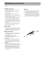
Safety warnings
For the installer
• When used as an extractor unit, the hood must
be fitted with a 120mm diameter duct.
Attention: The duct is not supplied and
must be purchased separately.
• When installing the hood, make sure you
respect the following minimum distance
from the top edge of the cooking hob/ring
surfaces:
electric cookers 650 mm
gas cookers 700 mm
The hood can be installed above these heights
but for optimum performance it should be
installed at the distance quoted for the
appropriate heat source.
• The national Standard on fuel-burning systems
specifies a maximum depression of 0.04 mbar
in such rooms.
• The air outlet must not be connected to
chimney flues or combustion gas ducts. The air
outlet must under no circumstances be
connected to ventilation ducts for rooms in
which fuel-burning appliances are installed.
• The air outlet installation must comply with the
regulations laid down by the relevant
authorities.
• When the unit is used in its extractor version, a
sufficiently large ventilation hole must be
provided, with dimensions that are approxi-
mately the same as the outlet hole.
• National and regional building regulations
impose a number of restrictions on using hoods
and fuel-burning appliances connected to a
chimney, such as coal or oil room-heaters and
gas fires, in the same room.
• Hoods can only be used safely with appliances
connected to a chimney if the room and/or flat
(air/environment combination) is ventilated
from outside using a suitable ventilation hole
approximately 500-600 cm
2
large to avoid the
possibility of a depression being created during
operation of the hood.
• If you have any doubts, contact the relevant
controlling authority or building inspector’s
office.
• Since the rule for rooms with fuel burning
appliances is “outlet hole of the same size as
the ventilation hole”, a hole of 500-600 cm
2
,
which is to say a larger hole, could reduce the
performance of the extractor hood.
• If the hood is used in its filtering function, it will
operate simply and safely in the above
conditions without the need for any of the
aforementioned measures.
• When the hood is used in its extractor function,
the following rules must be followed to obtain
optimal operation:
— short and straight outlet ducting
— keep bends in outlet ducting to a minimum
— never install the ducts with an acute angle,
they must always follow a gentle curve.
— keep the duct as large as possible
(preferably the same diameter as the
outlet hole).
• Failure to observe these basic instructions will
drastically reduce the performance and increase
the noise levels of the extractor hood.

4
For the user
• The cooker hood is designed to extract
unpleasant odours from the kitchen, it will
not extract steam.
• Always cover lighted elements, to prevent
excess heat from damaging the appliance. In
the case of oil, gas and coal fired cookers it is
essential to avoid open flames.
• Also, when frying, keep the deep frying pan on
the cooker top/cooker under careful control.
• The hot oil in the frying pan might ignite due to
overheating.
• The risk of self-ignition increases when the oil
being used is dirty.
• It is extremely important to note that
overheating can cause a fire.
• Never carry out any flambé cooking under
the hood.
• Always disconnect the unit from the power
supply before carrying out any work on the
hood, including replacing the light bulb.
• It is very important to clean the hood and
to perform maintenance and care of filters
at the recommended intervals. Failure to
do so could cause grease deposits to build
up, resulting in a fire hazard.
• The appliance is not intended for use by young
children or infirm persons without supervision.
• Young children should be supervised to ensure
that they do not play with the appliance.
• WARNING - Ensure that the appliance is
switched off before replacing the lamp to avoid
the possibility of electric shock.
This appliance is marked according to the
European directive 2002/96/EC on Waste Electrical
and Electronic Equipment (WEEE).
By ensuring this product is disposed of correctly,
you will help prevent potential negative
consequences for the environment and human
health, which could otherwise be caused by
inappropriate waste handling of this product.
The symbol
on the product, or on the
documents accompanying the product, indicates
that this appliance may not be treated as household
waste. Instead it shall be handed over to the
applicable collection point for the recycling of
electrical and electronic equipment.
Disposal must be carried out in accordance with
local environmental regulations for waste disposal.
For more detailed information about treatment,
recovery and recycling of this product, please
contact your local city office, your household waste
disposal service or the shop where you purchased
the product.

5
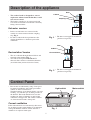
Description of the appliance
• The cooker hood is designed to extract
unpleasant odours from the kitchen, it will
not extract steam.
• The hood is supplied as an extractor unit and
can also be used with a recirculation version by
fitting a charcoal filter.
Extractor version
• In this version fumes are extracted to the
outside via a duct connected to the coupling
ring. Fig. 1.
• In order to obtain the best performance the
ducting should have a diameter equal to the
outlet hole.
Fig. 1
Recirculation Version
• The air is filtered through charcoal filters and
returned to the kitchen. Fig. 2.
• You will need original ELECTROLUX
charcoal filters for the recirculation function.
(Available from your local Service Centre)
Fig. 2
Coupling ring
Duct*
* The duct is not supplied and must be
purchased separately.
Cabinet
Charcoal filters
Duct*
Cabinet
* The duct is not supplied and must be
purchased separately.
Control Panel
• Best results are obtained by using a low speed
for normal conditions and a high speed when
odours are more concentrated.
Turn the hood on a few minutes before you start
cooking, you will then get an under pressure in
the kitchen. The hood should be left on after
cooking for about 15 minutes or until all the
odours have disappeared. The control switches
are located on the hood’s front panel:
Correct ventilation
If the cooker hood is to work correctly there must
be an under pressure in the kitchen. It is important
to keep the kitchen windows closed and have a
window in an adjacent room open.
Light switch
Motor switch
Fig. 3

6
• The hood must always be disconnected from the electricity supply before beginning any maintenance
work.
Cleaning the hood
• Clean the outside of the hood using a damp
cloth and a mild detergent.
• Never use corrosive, abrasive or flammable
cleaning products.
• Never insert pointed objects in the motor’s
protective grid.
• Wash the outside surfaces using a delicate
detergent solution. Never use caustic detergents
or abrasive brushes or powders.
• Only ever clean the control panel and filter grille
using a damp cloth and delicate detergents.
• It is very important to clean the hood and to
perform maintenance and care of filters at the
recommended intervals. Failure to do so could
cause grease deposits to build up, resulting in a
fire hazard.
• Clean the inner housing using a hot detergent
solution only (never use caustic detergents,
abrasive powders or brushes).
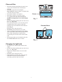
Grease filter
• The purpose of the grease filters is to absorb
grease particles which form during cooking and
it must always be used, either in the external
extraction or internal recycling function.
Metal grease filter
The metal grease filters must be removed and
washed, either by hand or in the dishwasher,
every four weeks.
Removing the metal grease filter
• Pull the handle rearwards. Then extract the
filter downwards. Fig. 4.
Hand washing
Soak grease filters for about one hour in hot
water with a grease-loosening cleaner, then
rinse off thoroughly with hot water. Repeat the
process if necessary. Refit the grease filters
when they are dry.
Dishwasher
Place grease filters in the dishwasher. Select
most powerful washing programme and highest
temperature, at least 65°C. Repeat the process.
Refit the grease filters when they are dry.
When washing the metal grease filter in the
dishwasher a slight discolouration of the filter
can occur, this does not have any impact on its
performance.
Maintenance and Care
Fig. 4
Handle
Warning
• Failure to observe the instructions on cleaning
the unit and changing the filters will cause a
fire hazard. You are therefore strongly
recommended to follow these instructions.
• The manufacturer declines all responsibility for
any damage to the motor or any fire damage
linked to inappropriate maintenance or failure to
observe the above safety recommendations.

7
Charcoal filter
• The charcoal filter should only be used if you
want to use the hood in the recirculation
function.
• To do this you will need an original
ELECTROLUX charcoal filter (available from
your local Service Centre).
• Two charcoal filters are required.
• This filter cannot be cleaned or reused.
• As a general rule, the charcoal filter(s)
should be changed once every four months.
• Fitting.
Remove the frame pushing the two side release
keys "a". Fig. 5a-b.
Fit each charcoal filter so to cover the plastic
grid that protect the fan wheel, then turn
clockwise the central handle of the charcoal
filter. Fig. 6.
Refit the frame (snap into place).
• To remove proceed in the reverse order.
• Always specify the hood model code number
and serial number when ordering replacement
filters. This information is shown on the
registration plate located on the inside of the
unit.
• The charcoal filter can be ordered from your
local ELECTROLUX Service Centre.
Changing the light bulb
• Disconnect the cooker hood from the main
supply.
• Remove the frame pushing the two side release
keys "a". Fig. 5a-b.
• Replace the old bulb with a new one of the
same type.
• Refit the frame (Snap into place).
• If the light does not come on, make sure the
bulb has been inserted correctly before
contacting your local Service Centre.
Fig. 6
Charcoal filters
a
a
b
b
a
Fig. 5
Frame

8
Something Not Working
If your appliance fails to work properly please carry out the following checks.
Symptom Solution
The cooker hood will not start. Check that: The hood is connected to the electricity supply.
Check that a fan speed has been selected
The cooker hood is not working Check that: The fan speed is set high enough for the task.
The grease filters are clean.
The kitchen is adequately vented to allow the entry of fresh air.
If set up for recirculation, check that the charcoal filter is still effective.
If set up for extraction, check that the ducting and outlets are not blocked.
The cooker hood has The safety cut-out device has been tripped.
switched off during operation. Turn off the hob and then wait for the device to reset.
If the hood has been installed below the heights indicated in the
installation instructions the motor will cut-out frequently which will
damage the hood.
If after all these checks, the problem persists, contact your local Service Centre, quoting the model and serial
number.
Please note that it will be necessary to provide proof of purchase for any in-guarantee service calls.
In-guarantee customers should ensure that the above checks have been made as the engineer will make a charge
if the fault is not a mechanical or electrical breakdown.

9
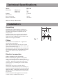
Technical Specifications
Model EFG 540
Dimensions Height (cm) 13,9
Width (cm) 52,4
Depth (cm) 28,9
Lighting 2 x 28 W
Grease filter 2
Power absorption 296 W
Electrical connection: 220-240 V
Subject to change without notice.
Installation
Unpacking
Check that the cooker hood has no damages.
Transportation damages should immediately be
reported to the company responsible for the
transportation.
Damages, faults and eventually missing details
should immediately be reported to the retailer.
Take care of the packing materials so that small
children cannot play with them.
Fitting
The hood is to be mounted into a cupboard or
custom built canopy hood.
When installed, the hood must be not less than
65cm. above electric burners or 70cm. above gas
or mixed-fuel burners (Fig. 7).
The hood can be installed above these heights but
for optimum performance it should be installed at
the distance quoted for the appropriate heat
source.
Electrical connection
Safety warnings for the electrician
Before connecting the appliance to the power
supply, check that the voltage indicated on the
rating plate corresponds to the mains power supply
available. Appliances fitted with a plug can be
connected to any standard power socket within
easy access.
Should it be necessary to provide a fixed
connection, the hood must only be installed by an
electrician authorised by the local electricity board.
When installing, an omnipolar disconnector with a
distance of at least 3 mm between contacts must
be provided.
Fixed connection of the appliance must only be
carried out by an authorised electrician.
Min
70 cm
Min
65 cm
Fig. 7

10
259
49
4
5
5
6
6
1
2
3
4
5
7
9
9
10
8
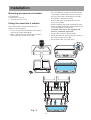
Installation
Fig. 8
Mounting accessories included
1 Coupling ring
8 metal screws 2,9 x 16
1 Allen key for torx screw.
Fixing the hood into a cabinet
This cooker hood is designed to be fitted to a
cabinet or similar support.
• Create an opening in the bottom of the cabinet
to insert the cooker hood (1-2).
• Make a hole on the top of the cabinet to fit the
duct and for the electrical cable (3).
• Fit a duct (4) long enough to reach the outside
(if the hood is used in the extractor version) or
the top of the cabinet (if the hood is used the
hood in the recirculation version).
• Remove the frame by pushing the two side
release keys (5-6).
• Fix the coupling ring on the exhaust hole of the
hood and make connection with the bottom end
of the duct (7a-b), seal with tape.
Attention: The duct is not supplied and
must be purchased separately.
• Prepare the electrical connection (8).
• Fit the hood into the opening and fix securely to
the cabinet with 8 screws (9).
• Fit the frame (10 - snap into place).

11

ZZZHOHFWUROX[FRPVKRS
LI2URE Ed. 07/15
-
 1
1
-
 2
2
-
 3
3
-
 4
4
-
 5
5
-
 6
6
-
 7
7
-
 8
8
-
 9
9
-
 10
10
-
 11
11
-
 12
12


Electrolux EFG540G/A User manual
- Category
- Cooker hoods
- Type
- User manual
Ask a question and I''ll find the answer in the document
Finding information in a document is now easier with AI
Related papers
-
AEG 5708 D User manual
-
Electrolux EFG 540 User manual
-
-
-
-
-
-
-
-
Other documents
-
Aeg-Electrolux DM8600-M/A User manual
-
-
-
-
-
-
-
No Brand CH700X/GB User manual
-
-