
INSTALLATION MANUAL
For Thermador Professional
®
Cooktops
MANUEL D'INSTALLATION
Des tables de cuisson Thermador Professional
®
MANUAL DE INSTALACIÓN
Para Parrillas de Thermador Professional
®
Models/
Modèles/
Modelos:
PCG30
PCG36
PCG48

Table of Contents
Questions?
1-800-735-4328
www.thermador.com
We look forward to hearing from you!
This Thermador Appliance is made by
BSH Home Appliances Corporation
5551 McFadden Ave.
Huntington Beach, CA 92649
Safety Instructions . . . . . . . . . . . . . . . . . . . . . . . . . . . .2
Before you Begin . . . . . . . . . . . . . . . . . . . . . . . . . . . . . . . . . . . . . . . . . . . . . . . . . 2
Important Installation Information . . . . . . . . . . . . . . .3
Step 1: Ventilation Requirements . . . . . . . . . . . . . . . . . . . . . . . . . . . . . . . . . . . . . . . . . . . . . . . 3
Step 2: Cabinet Preparation . . . . . . . . . . . . . . . . . . . . . . . . . . . . . . . . . . . . . . . . . . . . . . . . . . . 5
Step 3: Unpacking, Moving, Placing and Anchoring the Cooktop . . . . . . . . . . . . . . . . . . . . . . 10
Step 4: Gas Requirements and Hookup . . . . . . . . . . . . . . . . . . . . . . . . . . . . . . . . . . . . . . . . . 11
Step 5: Electrical Requirements, Connection and Grounding . . . . . . . . . . . . . . . . . . . . . . . . . 12
Step 6: Backguard Installation . . . . . . . . . . . . . . . . . . . . . . . . . . . . . . . . . . . . . . . . . . . . . . . . .13
Step 7: Burner Test and Adjustment . . . . . . . . . . . . . . . . . . . . . . . . . . . . . . . . . . . . . . . . . . . . 13
Installer Checklist . . . . . . . . . . . . . . . . . . . . . . . . . . . . . . . . . . . . . . . . . . . . . . . 14
To Clean and Protect Exterior Surfaces . . . . . . . . .15

English 1
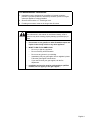
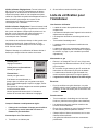
For Massachusetts Installations:
1. Installation must be performed by a qualified or licensed contractor,
plumber or gas fitter qualified or licensed by the state, province or region
where this appliance is being installed.
2. Shut-off valve must be a “T” handle gas cock.
3. Flexible gas connector must not be longer than 36 inches.
-- Do not store or use gasoline or other flammable vapors and
liquids in the vicinity of this or any other appliance.
-- WHAT TO DO IF YOU SMELL GAS
• Do not try to light any appliance.
• Do not touch any electrical switch.
• Do not use any phone in your building.
• Immediately call your gas supplier from a neighbor’s phone.
Follow the gas supplier’s instructions.
• If you cannot reach your gas supplier, call the fire
department.
-- Installation and service must be performed by a qualified
installer, service agency or the gas supplier.
WARNING:
If the information in this manual is not followed exactly, a fire or
explosion may result causing property damage, personal injury or
death.

English 2
Safety Instructions
Important Safety Instructions
READ AND SAVE THESE INSTRUCTIONS
APPROVED FOR ALL RESIDENTIAL APPLIANCES
FOR RESIDENTIAL USE ONLY
Before you Begin
IMPORTANT: Save these Instructions for the Local
Electrical Inspector’s use.
INSTALLER: Please leave these Instructions with this unit
for the owner.
OWNER: Please retain these instructions for future
reference.
WARNING:
Improper installation, adjustment, alteration,
service or maintenance can cause injury or
property damage. Refer to this manual. For
assistance or additional information consult a
qualified installer, service agency, manufacturer
(dealer) or the gas supplier.
NOTE:
This Cooktop is NOT designed for installation in
manufactured (mobile) homes or for installation in
Recreational Park Trailers.
DO NOT install this appliance outdoors.
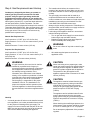
Data Rating Plate
Cooktop Models:
The data rating plate showing the model and serial
numbers of your cooktop is located on the underside of the
cooktop chassis near the gas inlet connection and electric
power cord. This information is required if customer service
is requested. Before installation, the model and serial
numbers should be entered in the appropriate spaces in
the "BEFORE CALLING FOR SERVICE" section near the
back of the Care and Use Manual. After installation,
accessing the information is difficult.
PLEASE READ ENTIRE INSTRUCTIONS BEFORE
PROCEEDING
IMPORTANT: LOCAL CODES VARY. INSTALLATION,
ELECTRICAL CONNECTIONS, GAS CONNECTIONS,
AND GROUNDING MUST COMPLY WITH ALL
APPLICABLE CODES.
Electrical Power Supply
30'' Model:
4 Burners - 120 VAC, 60 Hz., 1 Ph., 10 Amp circuit
36" Models:
6 Burners - 120 VAC, 60 Hz., 1 Ph., 10 Amp circuit
4 Burners with Electric Griddle - 120 VAC, 60 Hz., 1 Ph., 15
Amp circuit
48" Model:
6 Burners with Electric Griddle - 120 VAC, 60 Hz., 1 Ph., 15
Amp circuit
Gas Supply
Natural Gas – 6” min. to 14” max. water column (14.9 mb
to 34.9 mb)
Propane Gas – 11”min. to 14”max. water column (27.4 mb
to 34.9 mb)
WARNING
Disconnect power before installing.
Before turning power ON, be sure that all
controls are in the OFF position.
All sealed burners are rated at 18,000 BTU/HR (*15,000
BTU/HR on LP). *All models are convertible to LP/Propane
gas using an accessory conversion kit.
IMPORTANT
• A backguard must be utilized when there is less than a
12" horizontal clearance between combustible
materials and the back edge of the cooktop. The
Thermador Low Back backguard must be ordered
separately and installed at the rear of the cooktop. For
island installations and other installations with more
than 12" clearance, an optional stainless steel Island
Trim is available to cover the backguard mounting
flanges.
• Verify that the appliance is correct for the type of gas
being provided. Refer to “Step 4: Gas Requirements
and Hookup” on page 11 before proceeding with the
installation.

English 3
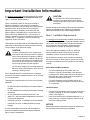
Important Installation Information
It is strongly recommended that this appliance be installed
in conjunction with a suitable overhead vent hood. (See
“Step 1: Ventilation Requirements”.)
Check local building codes for the proper method of
appliance installation. Local codes vary. Installation,
electrical connections and grounding must comply with all
applicable codes. In the absence of local codes the
appliance should be installed in accordance with the
National Electric Code ANSI Z223.1 current issue and
National Gas Code ANSI/NFPA 70 – current issue. In
Canada, installation must be in accordance with the CAN
1-B149.1 and .2 – Installation Codes for Gas Burning
Appliances and/or local codes.
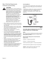
This appliance is equipped with an intermittent/interrupted
ignition device that cycles the two far left surface burners
on and off when in the ExtraLow
setting.
CAUTION
(1) When connecting the unit to propane gas,
make certain the propane gas tank is equipped
with its own high-pressure regulator in addition
to the pressure regulator supplied with this unit.
The maximum gas pressure to this appliance is
not to exceed 14.0 inches water column (34.9
mb) from the propane gas tank regulator.
(2) This unit is designed as a cooking appliance.
Based on safety considerations, never use it for
warming or heating a room.
Due to the high heat of the cooktop burners, installing a
microwave oven with a ventilation system over the cooktop
is not recommended.
This appliance complies with one or more of the following
standards:
• UL 858, Standard for the Safety of Household Electric
Ranges
• UL 923, Standard for the Safety of Microwave Cooking
Appliances
• UL 507, Standard for the Safety of Electric Fans
• ANSI Z21.1 American National Standard for Household
Cooking Gas Appliances
• CAN/CSA-C22.2 No. 113-M1984 Fans and Ventilators
• CAN/CSA-C22.2 No. 61-M89 Household Cooking
Ranges
It is the responsibility of the owner and the installer to
determine if additional requirements and/or standards
apply to specific installations.
CAUTION
To eliminate risk of burns or fire caused by
reaching over heated surface units, cabinet
storage located above the surface units should
be avoided.
Remove all tape and packaging before using the appliance.
Destroy the packaging after unpacking the appliance.
Never allow children to play with packaging material.
Step 1: Ventilation Requirements
It is strongly recommended that a suitable exhaust hood be
installed above the appliance. Downdraft ventilation should
not be used. The following table indicates the ventilation
hood options and blower capacity guidelines that are
recommended for use with all Thermador cooktops.
Due to the high heat capability of this unit, particular
attention should be paid to the hood and duct work
installation to assure it meets local building codes.
Do not install a microwave oven/ ventilator combination
above the cooktop, as these types of units do not provide
the proper ventilation and are not suitable for use with the
cooktop.
Select Hood and Blower Models:
• For wall installations the hood width must, at a
minimum, equal the nominal width of the appliance
cooking surface. Where space permits, a hood larger in
width than the cooking surface may be desirable for
improved ventilation performance.
• For island installations the hood width should, at a
minimum, overhang the appliance cooking surface by
3" on each side.
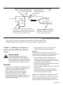
Hood Placement:
• For best smoke elimination, the lower edge of the hood
should be installed 30" above the appliance cooking
surface. (See Figure 1).
• If the hood contains any combustible materials (i.e., a
wood covering), it must be installed a minimum of 40”
above the cooking surface.
NOTICE:
Most hoods contain combustible components which must
be considered when planning the installation.

English 4
Consider Make-Up Air:
• Due to the high volume of ventilation air, a source of
outside replacement air is recommended. This is
particularly important for tightly sealed and insulated
homes.
• A qualified heating and ventilating contractor should be
consulted.
NOTE:
Ventilation hoods and blowers are designed for use with
single-wall ducting. Some local building codes may require
double-wall ducting. Before starting installation, consult
local building codes and agencies to insure that the
installation will meet local requirements.
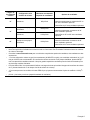
Cooktop
Width
Cooktop
Configuration
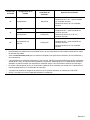
Minimum Recommended
Blower Capacity*
Ventilation Options
30” 4 burners 800 CFM
30” or 36” Pro Wall Hood
30” or 36” Custom Insert w/ optional blower
42” Island Hood w/ optional blower
36”
4 burners with griddle 1000 CFM 36” or 42” Pro Wall Hood
36” Custom Insert w/ optional blower
42” or 48” Island Hood w/ optional blower
6 burners 1100 CFM
48” 6 burners with griddle 1300 CFM
48”** or 54” Pro Wall Hood
48” Custom Insert w/ optional blower
54” Island Hood w/ optional blower
Important Notes:
• It is recommended that a Thermador Professional wall or island hood or custom insert is used with Thermador
Professional Cooktops.
• Refer to www.Thermador.com for a complete selection of Professional Ventilation options, Blowers, and
Accessories.
• * For high output gas cooktops (60,000 BTU or greater), the minimum of one (1) CFM of ventilation per 100 BTU is
recommended. If the cooktop has a griddle, add 200 CFM to the estimated blower capacity. Additional blower
capacity may be required for longer duct runs.
• For island applications, it is recommended to use a hood width that exceeds the width of the cooktop by 6”
(overlapping the cooktop by 3” on each end).
• **Not all 48” Pro Wall Hood models can accommodate a 1300 CFM blower option.
• CFM = “cubic feet per minute” (standard blower capacity rating).

English 5
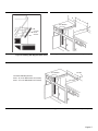
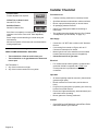
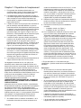
Step 2: Cabinet Preparation
1. To ensure professional results, the cabinet and
countertop openings should be prepared by a qualified
cabinet worker.
2. The clearances shown in Figure 1 are required. The
same clearances apply to island installations, except
for the overhead cabinets, which must have a space
wide enough to accept the island hood.
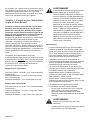
3. The cooktop is designed to hang from the countertop
by its side flanges. The countertop however, must be
strong enough to support this cooktop. It may be
necessary to add a supporting cleat along each side
(see Figure 2) or a 2 x 4 corner brace (see Figure 3
and Figure 4 and Detail A). Another alternative would
be to construct a deck to set the cooktop on.
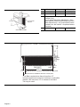
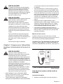
4. The cooktop can be installed in various positions with
the front either flush or projecting, depending on the
countertop’s depth. (See Figure 5, side view of
cooktop; see Figure 3, Figure 4, Figure 6 and Figure 7
for alternate mounting positions.)
5. The gas and electrical supply must be located in an
area that is accessible without requiring removal of the
cooktop. The appliance electrical power cord and gas
pipe connection are located on the left rear underside
of the cooktop, as shown in Figure 5 and Figure 9.
6. The maximum depth of over head cabinets installed on
either side of the hood is 13".
A 40-inch minimum clearance is required between the
cooking surface of the cooktop and the bottom of an
unprotected cabinet. A 30-inch distance can be used when
the bottom of the wood or metal cabinet is protected by not
less than 1/4 inch of a flame retardant material covered
with not less than No. 28 MSG sheet steel, 0.015 inch (0.4
mm) thick stainless steel, 0.024 inch (0.6 mm) aluminum,
or 0.020inch (0.5 mm) thick copper. Flame retardant
materials bear the mark:
UNDERWRITERS LABORATORIES INC. CLASSIFIED
MINERAL AND FIBER BOARDS SURFACE BURNING
CHARACTERISTICS
followed by the flame spread and smoke ratings. These
designations are shown as "FHC (FIame Spread/Smoke
Developed)." Materials with "O" flame spread ratings are
flame retardant. Local codes may allow other flame spread
ratings.
7. When there is less than a 12" horizontal clearance
between combustible material and the back edge of
the cooktop above the cooking surface, a Thermador
Low Backguard must be installed. (See Step 6). When
clearance to combustible material is over 12", a
Thermador Island Trim may be used. Attach the
backguard before sliding the appliance into the final
installed position.
8. Establish the centerline of the cooktop’s desired
location. It should be the same as the center of the
overhead ventilation hood.
9. Cut the openings for the following installations:
• Wall installation, see Figure 3.
• Island installation, see Figure 4.
10. For installation of a 48" cooktop above two side-by-side
Thermador Warming Drawers, Model No. WD24, refer
to Figure 8. Completing the installation as per Figure 8
will result in the left and right edges of the cooktop
being aligned with the left edge of the left-side warming
drawer and right edge of the right-side warming drawer.
If different alignment is desired, the 1-7/8" horizontal
distance between warming drawer cutouts may be
varied. However, maintain at least a 1-1/8" distance to
avoid interference between the warming drawers.
Attach a 90-degree elbow to the gas cooktop inlet pipe.
All above-the-countertop clearances must be
maintained, as shown in Figure 1.
As defined in the "National Fuel Gas Code" (ANSI
Z223.1/NFPA54-current issue).
NOTES:
• If a solid side cabinet wall exists on one or both sides,
you will need to notch the front corner of the cabinet to
match the countertop notch and to allow clearance for
the cooktop front (see Detail A, Figure 3 and Figure 4).
• If a supporting deck is used, the sides or bottom of the
cutout may be solid combustible or non-combustible
material. If the bottom is solid, provide a 8" by 8" cutout
in the left rear corner of the supporting deck. This will
provide clearance for the gas inlet and power cord,
while also allowing viewing of the product rating label.
• Always keep appliance area clean and free from
combustible materials, gasoline and other flammable
vapors and liquids.
• Do not obstruct the flow of combustion and ventilation
air to the unit.

English 6
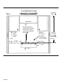
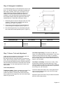
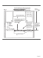
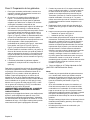
Figure 1: Clearance Requirements
30" to 36" Wide Hood for 30" Cooktop
36" to 42" Wide Hood for 36" Cooktop
48"
to 60" Wide Hood for 48" Cooktop
30" Min. from bottom of
Overhead Hood to Cooking
Surface (40"
or greater if
hood contains combustible
materials ).
0" Bottom
18" Min
.
0" Sides
40" Min. to
Combustible
Material
from Cooking
Surface.
Cooking Surface
VENT HOOD
13" Max.
depth of
overhead
cabinets
Combustible
Material
Horizontal
Min. Clearance
to Rear Wall:
0" with Backguard
12" with Island Trim
10" min.
both sides
"A"

English 7
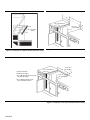
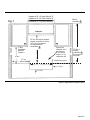
Figure 2: Installing Side Supports (both sides)
Counter
Sunk
Screws
Figure 3: Wall Installation with Countertop Backsplash
See Detail A
B
D
23-5/16”
B
Figure 4: Island Installation (No Countertop Backsplash)
See Detail A
3/4” Min.
D
22-13/16”
Vent Hood
Width Requirements
Island – 42" or 48"
Wide Hood
for 36" Cooktop
Island –
54" or 60"
Wide Hood for 48" Cooktop

English 8
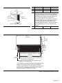
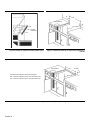
Detail A: (Front Face of Cabinet)
C
B
Corner Notch Detail
2 x 4 Corne
r
Support
7-11/16”
30” Cooktop 36” Cooktop 48” Cooktop
A 29-7/8” 35-7/8” 47-7/8”
B 3/8” 3/8” 13/16”
C 0” (Control Panel Projecting 1-1/4” from Base
Cabinet Face)
11/16” (Notch Required for Standard 24” - Deep
Base Cabinet, Control Panel Projecting 9/16” from
Base Cabinet Face) 1-1/4” (Control Panel Flush to
Cabinet Face - Min. 24-9/16” - Deep Base Cabinet
Required)
D 29-1/8” 35-1/8” 46-1/4”
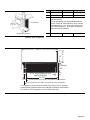
Figure 5: Side View of Cooktop
25-3/8”
12”
1/2”
Side
Flange
7-5/8”
5-1/4” TO CENTERLINE OF
GAS INLET
1-1/4”
Cabinet face for installation with projecting control panel
Cabinet face for installation with flush control panel
* Low Back required when there is less than 12”
horizontal clearance from back of cooktop to combustible
material. With more than 12” of clearance, the Island
Trim may be used.
23-5/16”

English 9
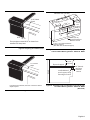
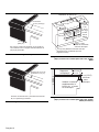
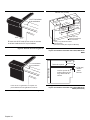
Figure 6: Projecting from Cabinet Front
Figure 7: Flush to Cabinet Front
Front projects outward 9/16" as shown from
standard 24"-deep base.
11/16” Notch
Depth
9/16”
1-1/4” Notch
Depth
Front flush with cabinets; minimum of 24-9/16" cabinet
depth required.
Figure 8a: Installation of 48” Cooktop above two side-by-
side Thermador Warming Drawers - Model No. WD24
Figure 8b: Installation of 48” Cooktop above two side-by-side
Thermador Warming Drawers - Model No. WD24
(Side View)
22-13/16"
(57, 9 cm)
46-1/4"
(117,5 cm)
22-1/2"
(57,2 cm)
7-11/16"
WD24
Cutout
WD24
Cutout
13/16"
(21 mm)
2-3/4" (7 cm) Vertical Distance
Between Cutouts
(See Side View for Wood Support)
1-7/8" (4,8 cm)
Horizontal Distance
Between Cutouts
Minimum 3/4" (19 mm)
0" to
1-1/4"
(0 - 32 mm)
See Fig. 4
and Table
Dimension C
(22, 9 cm) 9"
(19,52 cm)
Plywood support
Install additional
wood support along
front edge of cutout
REAR
2-3/4" (70 mm)
minimum
between
cutouts
7-11/16”
(19,52 cm)

English 10
All Installer supplied parts must conform to Local Codes.
*15 Amp 120 VAC electrical supply is required for 36" and 48" models with an electric griddle.
Step 3: Unpacking, Moving, Placing and
Anchoring the Cooktop
CAUTION
Proper equipment and adequate manpower
must be used in moving the appliance to avoid
damage and/or personal injury. The unit is
heavy and should be handled accordingly.
Important
• Verify that the appliance is correct for the type of gas
being provided. Refer to Step 4 before proceeding with
the installation.
• Attach the backguard before sliding the appliance into
the final installed position. See Step 6.
• Remove the outer carton and packing material from the
shipping base. Ensure that you have
all cooktop
components before proceeding.
• Remove the top grate castings and burner caps
to
reduce cooktop’s weight.
NOTE:
Leave adhesive-backed foam layer
over brushed-metal
surfaces, to protect finish from scratches, until the cooktop
is installed in its final position.
• Lift and place the cooktop in the opening. Be careful
not to pinch the power cord or gas inlet. Care should be
used not to scratch the griddle cooking plate.
• Make sure that the power cord is free and hanging
loose.
• The cooktop must be level for proper performance.
• Replace the cooking grates and burner caps. Ensure
that the burner caps are correctly seated on the burner
bases.
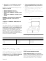
Griddle Tilt Adjustment (not all models)
Check the griddle adjustment by pouring two tablespoons
of water on the back of the griddle plate. The water should
slowly roll into the grease tray. If not, adjust the two screws
under the back of the plate. Start with one half turn counter-
clockwise (CCW) of the screws. Further adjustment should
be made by one-quarter turn until water slowly flows into
the grease tray.
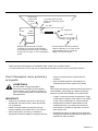
Figure 9: Bottom of Unit
Product Rating
Label/Serial Tag
Threading compounds must be
resistant to Propane Gas
1/2" NPT
gas flow
3/4” flex line
3” Min.
Power
Cord or
Conduit
A manual valve must be installed
external to the appliance, in an acces-
sible location from the front, for the
purpose of shutting off the gas supply.
3-Prong grounding type receptacle
connected to a properly grounded and
polarized electrical supply rated at 120VAC,
10 Amps, (or 15A*) Single Phase, 60 HZ.

English 11
Step 4: Gas Requirements and Hookup
Cooktops are shipped by the factory to operate on
natural gas.They must be converted for use with
propane. Verify the type of gas being used at the
installation site matches the type of gas used by the
appliance. If the location/job site requires conversion from
natural gas to propane (LP), contact the dealer where the
unit was purchased or contact Thermador. The field
conversion kit for the Professional Cooktops in this series is
Thermador Model PALPKITHC. Obey all instructions in this
kit for correct conversion of the gas regulator and settings
for the gas valves. Field conversion must be done by
qualified service personnel only.
Natural Gas Requirements:
Inlet Connection: 1/2” NPT (min. 3/4” dia. flex line)
Supply Pressure: 6” min. to 14” max. water column (14.9 to
34.9 mb)
Manifold Pressure: 5” water column (12.5 mb)
Propane Gas Requirements:
Inlet Connection: 1/2” NPT (min. 3/4” dia. flex line)
Supply Pressure: 11” min. to 14” max. water column (27.4
mb to 34.9 mb)
Manifold Pressure: 10” water column (24.9 mb)
WARNING
If a gas conversion kit is used, the kit shall be
installed by a qualified service agency in
accordance with the manufacturer’s instructions
and all applicable codes and requirements of
the authority having jurisdiction. If the
information in the instructions is not followed
exactly, a fire, explosion or production of carbon
monoxide may result causing property damage,
personal injury or loss of life. The qualified
service agency is responsible for the proper
installation of the kit. The installation is not
proper and complete until the operation of the
converted appliance is checked as specified in
the manufacturer’s instructions supplied with the
kit.
Hook Up
• A manual gas shut-off valve must be installed external
to the appliance, in a location accessible from the front,
for the purpose of shutting off the gas supply. The
supply line must not interfere with the back of the unit.
Make sure the gas supply is turned off at the manual
shut-off valve before connecting the appliance.
• The installer should inform the consumer of the
location of the gas shut-off valve. Make sure all users
know where and how to shut off the gas supply to the
cooktop.
• The gas supply connections shall be made by a
competent technician and in accordance with local
codes or ordinances. In the absence of local codes, the
installation must conform to the National Fuel Gas
Code ANSI Z223.1/NFPA54-current issue.
• Always use pipe-sealing compound or Teflon® tape on
the pipe threads, and be careful not to apply excessive
pressure when tightening the fittings.
• Leak testing of the appliance shall be in accordance
with the following instructions.
• Turn on gas and check supply line connections for
leaks using a soap and water solution.
• Bubbles forming indicate a gas leak. Repair all
leaks immediately after finding them.
WARNING
Do not use a flame of any kind to check for gas
leaks.
• All installer-supplied parts must conform to
applicable codes.
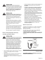
CAUTION
When connecting unit to propane gas, make
certain the propane gas tank is equipped with its
own high pressure regulator in addition to the
pressure regulator supplied with the appliance.
The pressure of the gas supplied to the
appliance regulator must not exceed a 14” water
column (34.9 mb).
CAUTION
The appliance must be isolated from the gas
supply piping system by closing its individual
manual shut-off valve during any pressure
testing of the gas supply piping system at test
pressures equal to or less than 1/2 psig
(3.5kPa).
The appliance and its individual shut off valve
must be disconnected from the gas supply
piping system during any pressure testing of the
system at test pressures in excess of 1/2 psig
(3.5kPa.).
When checking the manifold gas pressure, the
inlet pressure to the regulator should be at least
6.0" W.C. for natural gas or 11.0" for propane.
Do not attempt any adjustment of the pressure
regulator.

English 12
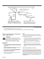
Step 5: Electrical Requirements,
Connection and Grounding
CAUTION
Improper grounding or reverse polarization will
cause malfunction (such as continuous sparking
of the burner igniters). This can damage the
appliance and can create a condition of shock
hazard. If the circuit is not correctly grounded
and polarized, it is the responsibility and
obligation of the installer and user to have the
existing receptacle changed to a properly
grounded and polarized receptacle. This must
be accomplished in accordance with all
applicable local codes and ordinances by a
qualified electrician. In the absence of local
codes and ordinances, the receptacle
replacement shall be in accordance with the
National Electric Code. (See Figure 10.)
• Before installing, turn power OFF at the service panel.
Lock service panel to prevent power from being turned
ON accidentally.
• Always disconnect appliance from the electric supply
either by disconnecting power cord or shutting off the
breaker before servicing the appliance.
• Before you plug in an electrical cord, be sure all
controls are in the OFF position.
• All 120 Volt cooktop models must be plugged into a
mating 3-Prong, Grounding-Type Receptacle. The
receptacle must be connected to a properly grounded
and polarized electrical power supply rated at 120VAC,
Single Phase, 60HZ. See “Electrical Power Supply
Over-current Protection Requirements” on page 12 for
proper over-current protection requirements for each
model.
• Observe all governing codes and ordinances when
grounding. In the absence of these codes or
ordinances observe National Electrical Code ANSI/
NFPA No. 70 current issue. See Figure 10 for
recommended grounding method.
• An electrical wiring diagram and schematic have been
attached to the bottom of the cooktop chassis for
access by a qualified service technician. Do not
remove or discard this important information.
Grounding Method
The cooktop is factory equipped with a power supply cord
with a three-prong grounding plug (with polarized parallel
blades).
IT MUST BE PLUGGED INTO A MATING, GROUNDING
TYPE RECEPTACLE THAT IS CONNECTED TO A
CORRECTLY POLARIZED 120 VOLT CIRCUIT (See
Figure 10).
THE THIRD, GROUND PRONG MUST NOT BE CUT OR
REMOVED UNDER ANY CIRCUMSTANCES.
NOTE:
If the 120V cooktop is installed and connected as specified
above, it will be completely grounded in compliance with
the National Electric Code.
Electrical Power Supply Over-current Protection
Requirements
4 Burners - 10 Amp circuit protection
6 Burners - 10 Amp circuit protection
4 Burners with electric griddle - 15 Amp circuit protection
6 Burners with electric griddle -15 Amp circuit protection
Installer - show the owner the location of the circuit
breaker or fuse. Mark it for easy reference.
Figure 10: Recommended Grounding Method for 120V
Models

English 13
Step 6: Backguard Installation
A Low Back backguard must be installed when there is less
than a 12" clearance between combustible materials and
back edge of cooktop. (See Figure 1 and Figure 5.) For
island installations and other installations with over 12"
clearance, an optional stainless
steel trim channel is
available to cover the backguard mounting flanges. Attach
the backguard before sliding the appliance into the final
installed position. Follow Steps A through C below:
1. Slide backguard over the two flanges on the rear of the
appliance. Fasten the front and back with the two
screws (see A, Figure 11) provided.
2. Fasten the top of the backguard to the wall with two
screws through the backguard. (See B, Figure 11.)
3. Place the backguard cap on top and fasten using the
two counter-sink screws provided. (See C, Figure 11.)
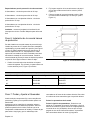
Step 7: Burner Test and Adjustment
Install any loose components, such as burner caps and
grates that may have been removed earlier.
Be certain that burner caps seat properly into the burner
bases. Before testing operation of the appliance, verify that
the unit and the gas supply have been carefully checked for
leaks and that the unit has been connected to the electrical
power supply. Turn the manual gas shut-off valve to the
open position.
Test Cooktop Burners
Test Burner Ignition. Select a cooktop burner knob. Push
in and turn counterclockwise to HI. The ignitor/spark
module will produce a clicking sound. Once the air has
been purged from the supply lines, the burner should light
within four (4) seconds.
Test Flame: High Setting. Turn burner on to HI. See
Figure 12 for appropriate flame characteristics. If any of the
cooktop burners continue to burn mostly or completely
yellow, verify that the burner cap is positioned properly on
the burner base, then re-test. If flame characteristics do not
improve, call Thermador.
Test Flame: Low Setting. Turn burner on to LO. Verify
that the flame completely surrounds the burner. There
should be a flame at each burner port and there should be
no air gap between the flame and the burner. If any burners
do not carry over, call Thermador.
The two far left burners feature XLO, causing the flame to
cycle on and off when the knob is set to the XLO range.
This is normal operation.
Repeat the Ignition and Flame Test procedures described
above for each cooktop burner.
Figure 11: Low Back Attachment
A
B
C
Low Back and Island Trim Model Numbers
Cooktop Size/Type 12” Low Back Island Trim*
30”
36”
48”
PA30GLBC
PA36GLBC
PA48GLBC
PA30GITC
PA36GITC
PA48GITC
*Requires a minimum of 12” horizontal clearance between back of appliance and combustible materials.

English 14
WHEN FLAME IS PROPERLY ADJUSTED:
• There should be a flame at each burner port.
• There should be no air gap between the flame and
burner port.
Call Thermador if:
1. Any of the burners do not light.
2. Any of the burners continue to burn yellow.
Installer Checklist
Final Check List
• Cooktop correctly positioned in countertop recess.
• Specified clearances maintained to cabinet surfaces.
• Burner caps positioned properly on burner bases.
• All packaging material removed.
• Island Trim or Backguard attached according to
instructions.
• The griddle plate tilted slightly forward. (See “Griddle
Tilt Adjustment (not all models)” on page 10.)
Gas Supply
• Connection: 1/2" NPT with a minimum 3/4" diameter
flex line.
• If converting from natural to LP gas, refer to LP
Conversion Instructions for details.
• Manual gas shut off valve installed in an accessible
location (without requiring removal of appliance).
• Unit tested and free of gas leaks.
Electrical
• For models with the electric griddle, a polarized and
grounded 120VAC receptacle with 15 AMP
over
current protection is provided for service cord
connection.
Operation
• All internal packing materials removed. (Check below
grates and grill pans.)
• Bezels centered on burner knobs, and knobs turn
freely.
• Purge air from gas system by operating one of the top
burners for several minutes.
• Each burner lights satisfactorily, both individually and
with other burners operating.
• Burner grates are correctly positioned.
Installer
• Give CARE and USE MANUAL and INSTALLATION
INSTRUCTIONS to your customer.
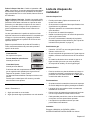
Figure 12: Flame Characteristics
If the flame is completely or mostly yellow, verify that the
regulator is set for the correct fuel. After adjustment,
retest.
Some orange-colored streaking is normal during the
initial start-up.
Allow unit to operate 4-5 minutes and re-evaluate before
making adjustments.
Yellow Flames:
Further adjustment is required.
Yellow Tips on Outer Cones:
Normal for LP Gas.
Soft Blue Flames:
Normal for Natural Gas.

English 15
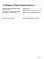
To Clean and Protect Exterior Surfaces
The stainless steel surfaces may be cleaned by wiping with
a damp soapy cloth. Any mild glass cleaner will remove
fingerprints and smears.
Follow all cleaning by rinsing with clear water. Wipe dry
with a clean soft cloth to avoid water marks. For
discolorations or deposits that persist, use a non-scratching
household cleanser or stainless steel polishing powder with
a little water and a soft cloth. For stubborn cases, use a
plastic scouring pad or soft bristle brush together with
cleanser and water. Rub lightly in direction of polishing
lines or "grain" of the stainless finish. Avoid using too much
pressure which may mar the surface.
Use a stainless steel cleaner/polish to protect the finish and
maintain appearance.
DO NOT allow deposits to remain for long periods of time.
DO NOT use ordinary steel wool or steel brushes. Small
bits of steel may adhere to the surface causing rust.
DO NOT allow salt solutions, disinfectants, bleaches or
cleaning compounds to remain in contact with stainless
steel for extended periods. Many of these compounds
contain chemicals which could prove harmful. Rinse with
water after exposure and wipe dry with a clean cloth.

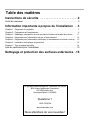
Table des matières
Questions?
1-800-735-4328
www.thermador.com
We look forward to hearing from you!
This Thermador Appliance is made by
BSH Home Appliances Corporation
5551 McFadden Ave.
Huntington Beach, CA 92649
Questions ?
1-800-735-4328
www.thermador.com
Nous attendons de vos nouvelles !
Cet appareil électroménager de Thermador est fait par
BSH Home Appliances Corporation
5551 McFadden Ave.
Huntington Beach, CA 92649
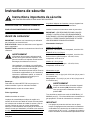
Instructions de sécurite . . . . . . . . . . . . . . . . . . . . . . .2
Avant de comencer . . . . . . . . . . . . . . . . . . . . . . . . . . . . . . . . . . . . . . . . . . . . . . . 2
Information importante à propos de l’installation . .3
Chapitre 1 : Exigences de ventilation . . . . . . . . . . . . . . . . . . . . . . . . . . . . . . . . . . . . . . . . . . . . 3
Chapitre 2 : Préparation de l’emplacement . . . . . . . . . . . . . . . . . . . . . . . . . . . . . . . . . . . . . . . . 6
Chapitre 3 : Déballage, manutention et mise en place et fixation de la table de cuisson . . . . 11
Chapitre 4 : Exigences pour l'alimentation du gaz et raccordement . . . . . . . . . . . . . . . . . . . . 12
Chapitre 5 : Exigences pour l’alimentation électrique, le branchement et la mise à la terre . . 13
Chapitre 6 : Installation de la plaque de protection . . . . . . . . . . . . . . . . . . . . . . . . . . . . . . . . . 14
Chapitre 7 : Test et réglage de brûler . . . . . . . . . . . . . . . . . . . . . . . . . . . . . . . . . . . . . . . . . . . 14
Liste de vérification pour l’installateur . . . . . . . . . . . . . . . . . . . . . . . . . . . . . . . . 15
Nettoyage et protection des surfaces extérieures .16
Page is loading ...
Page is loading ...
Page is loading ...
Page is loading ...
Page is loading ...
Page is loading ...
Page is loading ...
Page is loading ...
Page is loading ...
Page is loading ...
Page is loading ...
Page is loading ...
Page is loading ...
Page is loading ...
Page is loading ...
Page is loading ...
Page is loading ...
Page is loading ...
Page is loading ...
Page is loading ...
Page is loading ...
Page is loading ...
Page is loading ...
Page is loading ...
Page is loading ...
Page is loading ...
Page is loading ...
Page is loading ...
Page is loading ...
Page is loading ...
Page is loading ...
Page is loading ...
Page is loading ...
Page is loading ...
Page is loading ...
Page is loading ...
Page is loading ...
Page is loading ...
-
 1
1
-
 2
2
-
 3
3
-
 4
4
-
 5
5
-
 6
6
-
 7
7
-
 8
8
-
 9
9
-
 10
10
-
 11
11
-
 12
12
-
 13
13
-
 14
14
-
 15
15
-
 16
16
-
 17
17
-
 18
18
-
 19
19
-
 20
20
-
 21
21
-
 22
22
-
 23
23
-
 24
24
-
 25
25
-
 26
26
-
 27
27
-
 28
28
-
 29
29
-
 30
30
-
 31
31
-
 32
32
-
 33
33
-
 34
34
-
 35
35
-
 36
36
-
 37
37
-
 38
38
-
 39
39
-
 40
40
-
 41
41
-
 42
42
-
 43
43
-
 44
44
-
 45
45
-
 46
46
-
 47
47
-
 48
48
-
 49
49
-
 50
50
-
 51
51
-
 52
52
-
 53
53
-
 54
54
-
 55
55
-
 56
56


Thermador PCG364NL Installation guide
- Type
- Installation guide
- This manual is also suitable for
Ask a question and I''ll find the answer in the document
Finding information in a document is now easier with AI
in other languages
- français: Thermador PCG364NL Guide d'installation
- español: Thermador PCG364NL Guía de instalación
Related papers
-
Thermador PCD484EE Installation guide
-
Thermador PCG304E01 Installation guide
-
-
-
-
-
Thermador PCG30 User manual
-
-
-
Other documents
-
FiveStar TTN0377S User manual
-
-
 Five Star Ranges PN047-7 User manual
-
 Range Kleen PSC366 User manual
-
Fisher & Paykel CP-486GL User manual
-
-
Bosch NEM7360UC/02 Installation guide
-
Bosch NGP745UC/02 Installation guide
-
Maytag KGCG260S Installation Instructions Manual
-
DCS CPV366N Installation guide

