Page is loading ...

KRAMER ELECTRONICS Ltd.
USER MANUAL
Twisted Pair Transmitters and Receivers
Models:
TP-1xl, TP-2xl, TP-6, TP-11N,
TP-12N, TP-11xl, TP-12xl
Kramer Tools
Models:
704, 705, 707, 708, 709, 710, 711(xl), 712(xl)
IMPORTANT: Before proceeding, please read the paragraph entitled
"Unpacking and Contents:"

KRAMER ELECTRONICS LTD.
i
Contents
INTRODUCTION
UNPACKING AND CONTENTS
GETTING STARTED
Factors Affecting Quality of Results
Optional Accessories
TWISTED PAIR INTERFACES AND KRAMER TOOLS
A WORD ON BALANCED LINE TECHNOLOGY AND TWISTED PAIR INTERFACES
TWISTED-PAIR INTERFACES
TECHNICAL SPECIFICATIONS
Getting to Know the TP-1xlVideo Line Transmitter
Getting to Know the TP-2xlVideo Line Receiver
Getting to Know the TP-6Twisted-Pair Line Amplifier
Getting to Know the TP-11N Video/Audio Twisted-Pair Line Transmitter
Getting to Know the TP-12N Video/Audio Twisted-Pair Line Receiver
Getting to Know the TP-11xl Video/Audio Twisted-Pair Line Transmitter
Getting to Know the TP-12xl Video/Audio Twisted-Pair Line Receiver
KRAMER TOOLS
TECHNICAL SPECIFICATIONS for theKRAMER TOOLS
Getting to Know the 705/704 Video Line Transmitter/Receiver
Getting to Know the 707/708 Video/Audio Line Transmitter/Receiver
Getting to Knowthe 709/710 Y/C Line Transmitter/Receiver
Getting to Know the 711/712 (xl) AV Line Transmitter/Receiver
INSTALLATION
How to Setup a Twisted-Pair System
CONNECTING TO VIDEO DEVICES
Connecting Twisted-Pair Interfaces to Video Devices
Connecting Kramer Tools to Video Devices
CONNECTING TO AUDIO DEVICES
Connecting Twisted-Pair Interfaces to Audio Devices
Connecting Kramer Tools to Audio Devices
USING THE TWISTED-PAIR INTERFACESKRAMER TOOLS
Powering on the Twisted-pair Interfaces/Kramer Tools
Looping
Polarity
Gain Control
HF/EQ. Control
Y/C Control
Y Gain Control 19
C Gain Control 19
Y EQ. Control 19
Audio Control
Using a Microphone
Typical Video/Stereo Audio Twisted Pair Link
Typical Video/Stereo Audio Kramer Tools Setup
MAINTENANCE OF THE TWISTED PAIR INTERFACES/KRAMER TOOLS
TROUBLESHOOTING
Power And Indicators
Video Signal
Audio Signal

KRAMER ELECTRONICS LTD.
ii
Figures
FIGURE 1: TP-1XL
FRONT/REAR PANEL FEATURES
FIGURE 2: TP-2XL FRONT/REAR PANEL FEATURES
FIGURE 3: TP-6 FRONT/REAR PANEL FEATURES
FIGURE 4: TP-11N FRONT/REAR PANEL FEATURES
FIGURE 5: TP-12N FRONT/REAR PANEL FEATURES
FIGURE 6: TP-11XL FRONT/REAR PANEL FEATURES
FIGURE 7: TP-12XLFRONT/REAR PANEL FEATURES
FIGURE 8: / FRONT/REAR PANEL FEATURES
FIGURE 9: / FRONT/REAR PANEL FEATURES
FIGURE 10: / Y/C FRONT/REAR PANEL FEATURES
FIGURE 11: /Y/C FRONT/REAR PANEL FEATURES
FIGURE 12: TYPICAL VIDEO/STEREO AUDIO TWISTED PAIR LINK
FIGURE 13: EXTENSION OF RANGE
FIGURE 14: TYPICAL VIDEO/STEREO AUDIO KRAMER TOOLS SETUP
FIGURE 15: LOCATING THE INTERNAL FUSES
Tables
TABLE 1:TP-1XLFRONT/REAR PANEL FEATURES
TABLE 2:TP-2XLFRONT/REAR PANEL FEATURES
TABLE 3:TP-6 FRONT/REAR PANEL FEATURES
TABLE 4:TP-11N FRONT/REAR PANEL FEATURES
TABLE 5:TP-12N FRONT/REAR PANEL FEATURES
TABLE 6:TP-11XL FRONT/REAR PANEL FEATURES
TABLE 7:TP-12XLFRONT/REAR PANEL FEATURES
TABLE 8: FRONT/REAR PANEL FEATURES
TABLE 9: FRONT/REAR PANEL FEATURES
TABLE 10: FRONT/REAR PANEL FEATURES
TABLE 11: FRONT/REAR PANEL FEATURES
TABLE 12: FRONT/REAR PANEL FEATURES
TABLE 13: FRONT/REAR PANEL FEATURES
TABLE 14: FRONT/REAR PANEL FEATURES
TABLE 15: FRONT/REAR PANEL FEATURES

KRAMER ELECTRONICS LTD.
1
1.
INTRODUCTION
Congratulations on the purchase of this Kramer Electronics device. Since 1981 Kramer is dedicated to the
development and manufacture of high quality video/audio equipment. Throughout this period the Kramer line
has become an integral part of many of the best production and presentation facilities around the world. In
recent years, Kramer has redesigned and upgraded most of its lines, rendering the products more efficient and
“user-friendly”. Kramer’s line of professional video/audio electronics is one of the most versatile and complete
available and is a true leader in terms of quality, workmanship, price/performance ratio and innovation. In
addition to the devices presented here, Kramer offers a vast range of high quality distribution amplifiers,
switchers, processors, interfaces, controllers and computer-related products.
2.
UNPACKING and CONTENTS
The items contained in the Kramer package are listed below. Please save the original box and packaging
materials for possible future transportation and shipment of the device.
A Kramer “twisted pair” receiver / transmitter
AC power cable (where applicable)
User Manual
Kramer concise product catalog
4 rubber feet
3.
GETTING STARTED
The fastest way to get started is to slow down and do everything right the first time. Taking 15 minutes to read
the manual may save a few hours later, and usually there is no need to read the whole manual. Since each
section opens with an overview of the section, users may determine its necessity for their particular needs.
3.1 Factors Affecting Quality of Results
There are many factors affecting the quality of results when signals are transmitted via coaxial cable from a
source to an acceptor:
Connection cables
- Low quality cables are susceptible to interference. They degrade signal quality due
to poor matching, and cause elevated noise levels. They should therefore be of the best quality.
Sockets and connectors of the sources and acceptors
- So often ignored, they should be of highest
quality since "Zero Ohm" connection resistance is the target. Sockets and connectors must also match the
required impedance (75ohm in video). Cheap, low quality connectors tend to rust, thus causing breaks in the
signal path.
Amplifying circuitry
- Must have quality performance when the desired end result is high linearity, low
distortion and low noise operation.
Distance between sources and acceptors
- Plays a major role in the final result. For long distances
(over 15 meters) between sources and acceptors, special measures should be taken in order to avoid cable
losses. These include using higher quality cables, adding line amplifiers, or using twisted pair or fiber optic
codecs.
Interference from neighboring electrical appliances
- These can have an adverse effect on signal
quality. Balanced audio lines are less prone to interference, but unbalanced audio should be installed far from
any main power cables, electric motors, transmitters, etc., even when the cables are shielded.
3.2 Optional Accessories
The following accessories, available from Kramer, can enhance implementation of other Kramer devices. For
information regarding cables and additional accessories, contact your Kramer dealer.
RK-50R/RK-80 Rack Mechanical Adapters
-
Used to adapt non-standard size machines to a
standard 1U rack. One or more machines may be installed on each adapter
.
BNC "Y" Connector
-
Used for looping purposes and splits the incoming signal to enable connection
of an additional machine.
Termination Plug
-
Used to terminate the line to 75ohm for proper matching
.

KRAMER ELECTRONICS LTD.
2
SP-11
is a studio quality video processor with a unique combination of switching, distributing, and
transcoding capabilities. It can be serially connected between a receiver and an acceptor for video/audio
processing. It is designed primarily to control video properties such as hue, color, black level, brightness etc.
The SP-11 has a total of four inputs (two composite video, and two s-Video), and the selection is via a simple
front-panel. The desired input is then processed and routed to all four outputs simultaneously via internal
composite/s-Video transcoding. Eight independent adjustments are provided including VIDEO GAIN down
to full fade, log or linear DEFINITION, log or linear CONTRAST, COLOR saturation, BLACK level, and
separate RED, GREEN, and BLUE level controls. The screen SPLITTER provides “before and after”
comparison on one monitor. Audio inputs are switched with their respective video inputs in an "Audio-
follow-Video" order. The
SP-11
is dependable, rugged, and fits in one vertical space of a standard 19” rack.
VM-5S
(
1:5
Video Stereo Audio Distribution Amplifier)
is an exceptionally high performance 1:5
distribution amplifier for video and stereo audio signals that
can be serially connected between a receiver and
an acceptor for video/audio distribution purposes. It accepts one input signal, (composite, single component,
or serial digital video), and distributes it to five identical outputs using BNC connectors for video, and RCA
connectors for audio. The
VM-5S
is typically used for composite video sources such as VCR’s, cameras,
etc., but its wide video bandwidth, exceeding 350MHz, also allows it to be used for high-resolution video
signals, SDI (serial digital) video, and other specialized analog and digital signals. Video output signals can
be AC or DC coupled and inputs can be looped using an external termination switch to create larger systems.
The machine can handle either unbalanced stereo, or it can be easily adapted to handle balanced mono audio
signals. The
VM-5S
is rugged, and is housed in a convenient half-rack sized enclosure for desktop use. It can
also be rack mounted using the
RK-80
kit, which holds two units in one vertical space of a standard 19” rack.
VM-10ARII -
is a video/audio distribution amplifier designed for studio and other demanding
applications, and it can be serially connected between a receiver and acceptor(s) for video/audio distribution
purposes. The
VM-10ARII
has looping video and stereo audio inputs, each splitting to 10 outputs. The user
may choose unbalanced stereo or balanced mono audio on the front panel switches. The output audio and
video levels, as well as video cable EQ. may be adjusted via trimmers, accessible from the front panel. The
video outputs are in two blocks of 5 outputs each, where each block may be individually trimmed for level
and cable EQ., thereby achieving different compensations for different cable lengths. Several
VM-10ARII
units may be chained through the looping inputs. Output video signals are DC or AC coupled (user
selectable) for maximum flexibility.
VS-1201xl –
is a Vertical Interval Switcher, that can be serially connected between a receiver and an
acceptor for video switching purposes. It provides effortless switching from twelve composite video/stereo
audio inputs to one output (video and audio). The glitch-free switching is performed during the vertical
interval, either of source no. 1, or of the external sync socket. The switcher may be controlled in four ways:
Touch buttons, RS-232, RS-485 and contact closure via a remote socket on the back of the machine. The
machine can be interconnected and cascaded, (2
VS-1201xl
machines become 24x1, etc.) or operated in
parallel (3
VS-1201xl
machines become a 12x1 video component switcher). Video signal bandwidth is
250MHz , thus meeting the requirements of the most demanding applications, and ensuring that the machine
remains transparent even in the most critical production, presentation, or broadcast applications. The
VS-
1201xl
family is dependable, rugged, and each fits in one vertical space of a standard 19” rack.
VIDEO TESTER -
A unique, patented, indispensable tool for the video professional, the Video Tester
is used to examine a video path leading to/from a machine. By pressing only one touch switch it can trace
missing signals, distinguish between good and jittery (VCR sourced) signals, and identify the presence of
good signals. Whenever a video signal is missing, because of bad connections, cable breaks or faulty sources,
the Video Tester is sufficient to trace the source of the problem. There is no need for oscilloscopes,
waveform monitors or vectorscopes to trace and rectify such common problems. Indispensable for fieldwork,
the Tester checks for sync and odd/even data in the signal and is not triggered by noise, hum or even by a
15kHz non-video source. The
Video Tester
is compact (not much bigger than a cigarette box); resides in a
sturdy plastic housing with pocket clip, and will typically operate for several months from a single 9-Volt
battery.

KRAMER ELECTRONICS LTD.
3
4.
TWISTED PAIR INTERFACES AND KRAMER TOOLS
This manual includes information about configuration, operation, maintenance and optional accessories for the
following Twisted Pair Interfaces and Kramer Tools (please note that machines from the same family have
several features in common):
TP-1xl- Video Line Transmitter
TP-12xl - Video/Audio Line Receiver
TP-2xl - Video Line Receiver
704, 705 - Video Line Transmitter/Receiver
TP-6 - Twisted Pair Line Amplifier
707, 708 - Video/Audio Line Transmitter/Receiver
TP-11N - Video/Audio Line Transmitter
709, 710 - Y/C Line Transmitter/Receiver
TP-12N - Video/Audio Line Receiver
711(xl), 712(xl) - AV Line Transmitter/Receiver
TP-11xl - Video/Audio Line Transmitter
5.
A WORD ON BALANCED LINE TECHNOLOGY AND TWISTED PAIR
INTERFACES
Video/Audio Balanced Line systems allow transmission of high quality (high signal/noise ratio) video and
audio signals on low quality twisted-pair cables thanks to a procedure of noise reduction. The process
principally consists of two main manipulative phases; in the first, the signal is electrically inverted in the
transmitter. The inverted and non-inverted signals are then transmitted together on a twisted-pair line,
accumulating noise along the way. At the receiver, the inverted signal is subtracted from the non-inverted one,
resulting in a signal of twice the amplitude (A – (-A) = 2A). Since the two inverted signals pick up the same
noise (with equal polarity) the subtraction eliminates the noise.
By using twisted-pair technology, simplification of studio and industrial wiring is easily achieved. The price of
Twisted Pair wires is far lower than that of coaxial cables, so it is an attractive alternative for an extensive array
of applications. Some of the twisted pair machines are fed by a 12VDC source, and are therefor suitable for
fieldwork. The DC fed machines can power one another using a 4-wire setup.
The Twisted Pair interfaces are divided into three families as follows:
Twisted Pair Transmitters
- Used to convert video and audio signals to a twisted-pair signal format
(balanced line). Some of the machines convert only video, while some convert video and also two channels
of audio to a single twisted-pair compatible signal, thus sparing the use of three coaxial cables. User-
accessible trimmers are sometimes used for signal level and cable compensation.
Twisted Pair Receivers
- Used to convert a twisted-pair format signal back to video and audio signals.
Receivers having a looping capability allow receivers to be chained together. Some have a polarity switch,
allowing the user to connect the wire using any polarity.
Twisted Pair Amplifiers
-
used to extend the operating distance of the twisted-pair system by adding
amplification and cable compensation along the twisted-pair wire. Machines which feed the power via a 4-
wire system eliminate the need to forward a power source to a remote location where the line amplifier is
installed.

KRAMER ELECTRONICS LTD.
4
6.
TWISTED-PAIR INTERFACES
This section describes the controls and connections of the Twisted Pair Interfaces. Getting acquainted with all of
them helps understanding the full potential of the machine.
6.1 TECHNICAL SPECIFICATIONS (TP-1xl, TP-2xl, TP-6, TP-11N, TP-12N, TP-11xl, TP-12xl)
TP-1xl TP-2xl TP-6 TP-11N / TP-11xl TP-12N / TP-12xl
! "#$
%
&
'
( )
%
! "#$
"#$*+
"#$,+
%
"#$, "#$,*+
' -(+
()
%%
..%% ,& '
%%+
.%%
.&/ 0 1.%% ,/ 0 1&$.%%
/ 0 1$.%%
/ 0 1&$.%%
/ 0 1$.%%
!
&2 .%% &2 '
%%+
%&32
"#
&..%% %&,45 & '
%%+
%&
$
-2 .%% %&.2 '
%%+
-2 %%
$#% $
6%%
% #
#
7 0 8,&/ 0 19 $6
&
7 0 8,&/ 0 1
9 $& +
% ##
&' ( () *
& *, *&
&:*&:*&4:+
& * *.&,
&:*,&:*&.:+
& *, *&
&:*&:*&4:+
' +
%&& &&+)* %&,& %&.&+
)*&
%&4& &4&+)*&
"
,#%
,&.) .&) %&4) &) .&)
"
,
,.%) %%0 1 ) ; &<&)&+ ,5 .% ) ,.%) %%0 1 ) ; &<&)&+

KRAMER ELECTRONICS LTD.
5
6.2 Getting to Know the TP-1xl Video Line Transmitter
The Kramer
TP-1
xl is a high performance composite video to twisted pair transmitter, designed to transmit video
signals over long distances using common twisted-pair cable. Combined with the
TP-2
xl, this set of machines is an
upgrade of the
TP-1N
/
TP-2N
pair (now discontinued). Using good quality cable, the system can maintain the
bandwidth of an industrial color video signal up to 4000 ft. (1.3km) vs. 1000ft of the old version, and broadcast quality
(up to 12 MHz) for as much as 750 ft. (250 meters). At shorter distances, bandwidth of 100 MHz is easily achieved.
The set provides gain and high frequency compensation controls to optimize levels in extremely long runs. Kramer
twisted-pair adapters solve remote monitoring requirements without using more costly fiber or wireless transmission
systems. Using the
RK-50R
kit, a set of
TP-1
xl/
TP-2
xl can be mounted in a standard 19” rack.
NOTE
For Installation, operation, maintenance and troubleshooting instructions please refer to sections 8-13.
Figure
: TP-1xl Front/Rear Panel Features
Table 1: TP-1xl Front/Rear Panel Features
No.
Feature Function
1. Illuminated power switch Supplies power to the unit.
2.
CV in
BNC connector Video input.
3.
GAIN
trimmer Controls video level of output.
4.
HF
trimmer Controls cable equalization of the video output.
5. LINE out terminal block Amplified and buffered balanced video output.
6. Power Connector
A 3-prong AC connector allows power to be supplied to the unit.
Directly underneath this connector, a fuse holder houses the appropriate
fuse.

KRAMER ELECTRONICS LTD.
6
6.3 Getting to Know the TP-2xl Video Line Receiver
The Kramer
TP-2
xl is a high performance composite video to twisted pair receiver, designed to receive video signals
over long distances using common twisted pair cable. Combined with the
TP-1
xl this set of machines is an upgrade of
the TP-1N/TP-2N pair (now discontinued). Using good quality cable, the system can maintain the bandwidth of an
industrial color video signal up to 4000 ft. (1.3km) vs. 1000ft of the old version, and broadcast quality (up to 12 MHz)
for as much as 750 ft. (250 meters.) At shorter distances, bandwidth of 100 MHz is easily achieved. The set provides
gain and high frequency compensation controls to optimize levels in extremely long runs. Kramer twisted pair
adapters solve remote monitoring requirements without using more costly fiber or wireless transmission systems.
Using the
RK-50R
kit, a set of
TP-1
xl/
TP-2
xl can be mounted in a standard 19” rack.
NOTE
For Installation, operation, maintenance and troubleshooting instructions please refer to sections 8-13.
Figure
: TP-2xl Front/Rear Panel Features
Table 2: TP-2xl Front/Rear Panel Features
No.
Feature Function
1. Illuminated power switch Supplies power to the unit.
2.
CV out
BNC connector Amplified and buffered video output.
3.
GAIN
trimmer Controls video level of output.
4.
HF
trimmer Controls cable equalization of the video output.
5.
LINE in
terminal block Balanced input.
6.
“Term” Switch
Pressed to “ Term” position when the machine is the last on the line and not
looped.
7. Power Connector
A 3-prong AC connector allows power to be supplied to the unit. Directly
underneath this connector, a fuse holder houses the appropriate fuse.

KRAMER ELECTRONICS LTD.
7
6.4 Getting to Know the TP-6, Twisted-Pair Line Amplifier
The KRAMER TP-6, Twisted-Pair Line Amplifier, extends the range of the KRAMER TP (twisted-pair
transmitter-receivers) series, to almost any desired distance. The
TP-6
may receive its power source through the
twisted-pair wire (in a 4-wire setup) and, due to its very small power consumption, several units may be
cascaded and fed from one standard 12V DC feed. Basically, any number of
TP-6
units may be used in cascade
operation. Via rear-accessible trimmer controls, video and HF gain may be easily tuned to achieve best
performance.
NOTE
For Installation, operation, maintenance and troubleshooting instructions please refer to sections 8-13.
Figure
: TP-6 Front/Rear Panel Features
Table 3: TP-6 Front/Rear Panel Features
No.
Feature Function
1.
LED
(on front panel)
When turned on, indicates that the machine is powered
2.
GAIN
trimmer Controls level of output.
3.
HF trimmer Controls cable equalization of the output.
4.
LINE IN
telephone socket Balanced input.
5.
LINE OUT
telephone socket Amplified and buffered balanced output.
6.
12VDC
feed connector A DC connector that allows power to be supplied to the unit.

KRAMER ELECTRONICS LTD.
8
6.5 Getting to Know the TP-11N, Video/Audio Twisted-Pair Line Transmitter
The KRAMER TP-11N Video Line Transmitter sends a color video signal and a stereo audio signal over long
distances using a telephone wire or any other twisted-pair wire. The
TP-11N
maintains the bandwidth of an
industrial color video signal up to several hundred meters and broadcast quality (over 6 MHz) signals up to 100
meters. All three signals, video and the two audio channels, are transmitted simultaneously on the same wire in
real-time. By using the KRAMER TP-11N together with the TP-12N (Video/Audio Line Receiver) coax wiring
in a studio can be completely eliminated.
NOTE
For Installation, operation, maintenance and troubleshooting instructions please refer to sections 8-13.
Figure
: TP-11N Front/Rear Panel Features
Table 4: TP-11N Front/Rear Panel Features
No.
Feature Function
1.
Illuminated power switch Supplies power to the unit.
2.
RCA
Audio in
connectors
Audio
input.
3.
BNC
Video in
connector
Video input.
4.
LINE OUT
telephone socket Amplified and buffered balanced output.
5.
Power Connector
A 3-prong AC connector allows power to be supplied to the unit.
Directly underneath this connector, a fuse holder houses the
appropriate fuse.

KRAMER ELECTRONICS LTD.
9
6.6 Getting to Know the TP-12N Video/Audio Twisted-Pair Line Receiver
The KRAMER TP-12N Video/Audio Line Receiver works in conjunction with the TP-11N Video/Audio Line
Transmitter. The
TP-12N
allows parallel connection of several units on the same line (one transmitter/multiple
receivers), that can be tapped at any point without affecting image quality. When connecting several units, all
the termination switches on the rear panel of the
TP-12N
machines, except for the last on the line, should be
toggled to the Hi-Z position. The frequency response of the TP-12N matches that of the TP-11N transmitter,
and it provides polarity switching on the rear panel.
NOTE
For Installation, operation, maintenance and troubleshooting instructions please refer to sections 8-13.
Figure
: TP-12N Front/Rear Panel Features
Table 5: TP-12N Front/Rear Panel Features
No.
Feature Function
1.
Illuminated power switch Supplies power to the unit.
2.
GAIN
trimmer Controls video level of output (accessible from bottom).
3.
HF
trimmer Controls cable equalization of the video output (accessible from bottom).
4.
Term/Hi-Z
switch Selects "
Term
" or "
Hi-Z"
impedance (for looping select "
Hi-Z"
).
5.
LINE in
telephone socket Balanced input.
6.
Polarity switch Inverts the incoming balanced signal.
7.
BNC
Video out
connector
Amplified and buffered video output.
8.
RCA
Audio out
connectors
Amplified and buffered audio
output.
9.
Power Connector
A 3-prong AC connector allows power to be supplied to the unit.
Directly underneath this connector, a fuse holder houses the appropriate
fuse.

KRAMER ELECTRONICS LTD.
10
6.7 Getting to Know the TP-11xl, Video/Audio Twisted-Pair Line Transmitter
The KRAMER TP-11xl Video Line Transmitter, which is based on the latest technology, sends a color video
signal and a stereo audio signal over long distances using a telephone wire or any other twisted-pair wire. The
TP-11xl
maintains the bandwidth of an industrial color video signal up to several hundred meters and broadcast
quality (over 6 MHz) signals up to 100 meters. All three signals, video and the two audio channels, are
transmitted simultaneously on the same wire in real-time. By using the KRAMER TP-11xl together with the
TP-12xl
(Video/Audio Line Receiver) coax wiring in a studio can be completely eliminated.
NOTE
For Installation, operation, maintenance and troubleshooting instructions please refer to sections 8-13.
Audio IN
Video IN
Line OUT
R
L
FUSE
230 VAC
50/60Hz
5
1
3
4
2
Figure
: TP-11xl Front/Rear Panel Features
Table 6: TP-11xl Front/Rear Panel Features
No.
Feature Function
1 Illuminated power switch Supplies power to the unit.
2 RCA
Audio in
connectors
Audio
input.
3 BNC
Video in
connector
Video input.
4
LINE OUT
telephone socket Amplified and buffered balanced output.
5 Power Connector
A 3-prong AC connector allows power to be supplied to the unit.
Directly underneath this connector, a fuse holder houses the
appropriate fuse.

KRAMER ELECTRONICS LTD.
11
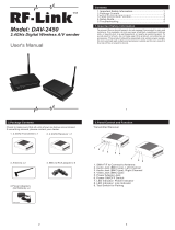
6.8 Getting to Know the TP-12xl Video/Audio Twisted-Pair Line Receiver
The KRAMER
TP-12xl
Video/Audio Line Receiver, which is based on the latest technology, works in
conjunction with the
TP-11xl
Video/Audio Line Transmitter. The
TP-12xl
allows parallel connection of several
units on the same line (one transmitter/multiple receivers) that can be tapped at any point without affecting
image quality. When connecting several units, all the termination switches on the rear panel of the
TP-12xl
machines, except for the last on the line, should be toggled to the Hi-Z position. The frequency response of the
TP-12xl
matches that of the
TP-11xl
transmitter, and it provides polarity switching on the rear panel.
NOTE
For Installation, operation, maintenance and troubleshooting instructions please refer to sections 8-13.
Audio Out
Video Out
Line In
Polarity
Term
Hi-z
FUSE
230 VAC
50/60Hz
6
7
8
9
5
1
3
4
2
Figure
: TP-12xl Front/Rear Panel Features
Table 7: TP-12
xl
Front/Rear Panel Features
No.
Feature Function
1 Illuminated power switch Supplies power to the unit.
2
GAIN
trimmer Controls video level of output (accessible from bottom).
3
HF
trimmer Controls cable equalization of the video output (accessible from bottom).
4
Term/Hi-Z
switch Selects "
Term
" or "
Hi-Z"
impedance (for looping select "
Hi-Z"
).
5
LINE in
telephone socket Balanced input.
6
Polarity
switch Inverts the incoming balanced signal.
7 BNC
Video out
connector
Amplified and buffered video output.
8 RCA Audio out connectors Amplified and buffered audio output.
9 Power Connector
A 3-prong AC connector allows power to be supplied to the unit.
Directly underneath this connector, a fuse holder houses the appropriate
fuse.

KRAMER ELECTRONICS LTD.
12
7.
KRAMER TOOLS
This section describes the controls and connections of the Kramer Tools. Getting acquainted with all of them
helps to understand the full potential of the machines.
7.1 TECHNICAL SPECIFICATIONS&-./(-.0(-.-(-.1(-.2(-3.(-33(-34*
704, 705 707, 708 709, 710 711(xl), 712(xl)
-.0=
-./=
-.-56
-.-6 ( )
* '
%&! &
-.16
-.2=' >+
#
>+
%&. +
-3.=$
-335=
-33='
()
..
-34=(?$
-347 =
-./=
@
+
-.0
=
-.-=
-.15=
-.16 ( )
'& ..%
-.1 =
-.26$
-3.=' >+
#
>+
%&. +
-33=(?$
-337 =
-345=
-34='
()
'
&,%
=,
)'=%
%
6
6.
%/ 0 1$..%
&./ 0 1$.%%
=%/ 0 1&$.
=.%0 1$..%
'+&
4&/ 0 1$. >+%%
6/ 0 1$.
6%%0 1$.
! &*
%&.2
%&2 %&%2
&2
"#&*
%&., %&. %&% %&.
89,
&2 %% + %&2 ,% + &2 %% + %&2 %% +
$
A %&,2 %% + A %&,2 %&42 %% + &,2 %% +
! +
-BB-=
-.0=$&&
-./=$&3&
BC &=
-.0=%3&
-./=%3&.
D5 BE =
$&4,&. +
% BC &+
=$.%. +
: >+=
%=$,&&
0 D$8(BC &=$,&&
0 (E / ) +=
%=$&4&4
68%&
9 & +$%&
9 &. BC &+
=!*F %+
4
) % ,
%&%3.2 %&%%,2
)
; #
&)
%&%32
&)
%&%..2
#
-BC &6
&-
&<
%6+&
-.1=-BC &6
-.-= /
!
'&
-' -0 $8G&
6
&-
%6+
-BC &!
,6+
6
,# -./=" 6
-.1=" 0 $H
''6
-3.=" 0 $H
&)
% ##
&' ( () *
, *& *,& &:*,&3:*%&34:
' +
%&,4& %&,&+)*& %&,& %&4&+)*& %&,4& %&,&+)*&
"
,#%
-.0=%&I
-./=%&I
%&I + %&I + -33=%&3I
-34=%&4I
" ,
, 5 % )
-336
, 5 4% )
-34=, 5 % )

KRAMER ELECTRONICS LTD.
13
7.2 Getting to Know the 705/704 Video Line Transmitter/Receiver
The KRAMER 705 Video Line Transmitter and the 704 Video Line Receiver, part of the KRAMER TOOLS
family, are used as a pair for transmitting video over long distances using a twisted-pair wire. A termination
switch allows several 704 receivers to be looped-through on the same line (one transmitter-multiple receivers.)
The frequency response of the pair is well over 6.7MHz, even at 400m. At shorter distances, they provide close
to broadcast level performance. The machines offer user controlled Gain and HF compensation.
NOTE
For Installation, operation, maintenance and troubleshooting instructions please refer to sections 8-13.
Figure
: 705/704 Front/Rear Panel Features
Table 8: 704 Front/Rear Panel Features
No.
Feature Function
1.
LOOP
telephone socket Provides video looping capability to increase number of outputs.
2.
INV
switch
Inverts the incoming balanced signal.
3.
Line IN
telephone socket Balanced input.
4.
Hi-Z
switch Selects "
Term
" or "
Hi-Z"
impedance (pressed=
Term
;
for end of line).
For looping select "
Hi-Z"
.
5.
Video OUT
BNC connector
Amplified and buffered video output.
6.
LEVEL trimmer
Adjusts the video level output (accessible from bottom).
7.
HF trimmer
Controls cable equalization of the video output (accessible from bottom).
8.
ON LED Illuminates when the machine is powered.
9.
12VDC
feed connector A DC connector that allows power to be supplied to the unit.
Table 9: 705 Front/Rear Panel Features
No.
Feature Function
1.
Line OUT
telephone socket Amplified and buffered balanced output.
2.
HF trimmer
Controls cable equalization of the output.
3.
LEVEL trimmer
Controls level of output.
4.
Video IN
BNC connector Video input.
5.
ON
LED
Illuminates when the machine is powered.
6.
12VDC
feed connector A DC connector that allows power to be supplied to the unit.

KRAMER ELECTRONICS LTD.
14
7.3 Getting to Know the 707/708 Video/Audio Line Transmitter/Receiver
The KRAMER 707 Video/Audio Line Transmitter and the 708 Video/Audio Line Receiver, of the KRAMER
TOOLS family, are used as a pair for transmitting video and mono audio over long distances using twisted-pair
wire. A termination switch allows several
708
receivers to be looped-through on the same line (one transmitter -
multiple receivers). This pair of machines is best at distances of up to 200 meters. At shorter distances, they
provide close to broadcast level performance. They also provide user controlled Gain and HF compensation.
NOTE
For Installation, operation, maintenance and troubleshooting instructions please refer to sections 8-13.
Figure
: 707/708 Front/Rear Panel Features
Table 10: 708 Front/Rear Panel Features
No
.
Feature Function
1.
Video OUT
BNC connector
Amplified and buffered video output.
2.
EQ. trimmer Controls cable equalization.
3.
Video Gain trimmer Controls video level of the outputs.
4.
Audio OUT
RCA connector Amplified and buffered audio
output.
5.
Term
pushbutton Selects "
Term
" or "
Hi-Z"
impedance (pressed=
Term).
For looping select "
Hi-Z"
.
6.
INV
pushbutton
Inverts the incoming video signal when pressed.
7.
LOOP
telephone socket Provides looping capability to increase number of outputs (to connect additional
receivers).
8.
Line IN
telephone socket Balanced input.
9.
ON
Led
Illuminates when the machine is powered.
10.
12VDC
feed connector A DC connector that allows power to be supplied to the unit.
Table 11: 707 Front/Rear Panel Features
No
.
Feature Function
1.
LINE OUT telephone socket Balanced output.
2.
Audio Level
trimmer Adjusts the audio level output.
3.
Cond. MIC
switch
Provides operation voltage to the microphone when pressed.
WARNING!
Only press the COND MIC switch when a condenser microphone is used with
the 707! For all other audio sources, the switch must not be pressed!
4.
Audio IN
RCA connector Audio
input
5.
Video IN
BNC connector
Video input.
6.
ON
Led
Illuminates when the machine is powered.
7.
12VDC feed connector A DC connector that allows power to be supplied to the unit.

KRAMER ELECTRONICS LTD.
15
7.4 Getting to Know the 709/710 Y/C Line Transmitter/Receiver
The KRAMER 709 Y/C Line Transmitter and the 710 Y/C Line Receiver, part of the KRAMER TOOLS
family, are used as a pair for transmitting s-Video (Y/C) over long distances using 2 twisted-pair sets of wires.
The frequency response of the pair is well over 8.4MHz, even at 200 meters. At shorter distances, they provide
close to broadcast level performance. The machines offer user controlled Y Gain, Y EQ. and Chroma Gain on
both transmitter and receiver. A termination switch allows several 710 receivers to be looped-through on the
same line (one transmitter - multiple receivers.)
NOTE
For Installation, operation, maintenance and troubleshooting instructions please refer to sections 8-13.
Figure
:
709/710 Y/C
Front/Rear Panel Features
Table 12: 710 Front/Rear Panel Features
No.
Feature Function
1.
Y/C OUTPUT 4p connector Amplified and buffered Y/C output.
2.
Y EQ.
trimmer Controls Y cable equalization.
3.
Y GAIN
trimmer Controls the Y gain.
4.
C GAIN
trimmer Controls the Chroma gain.
5.
Hi-Z/Term
pushbutton Selects "
Term
" or "
Hi-Z"
impedance (pressed=
Term).
For looping select
"
Hi-Z"
.
6.
IN C & Y
terminal block connector Twisted pair wire input.
7.
ON
Led
Illuminates when the machine is powered.
8.
12VDC
feed connector A DC connector that allows power to be supplied to the unit.
Table 13: 709 Front/Rear Panel Features
No.
Feature Function
1.
OUT C & Y terminal block connector Twisted pair wire output.
2.
Y GAIN trimmer Controls the Y gain.
3.
Y EQ.
trimmer Controls Y cable equalization.
4.
C GAIN
trimmer Controls the Chroma gain.
5.
Y/C INPUT
4p connector
Y/C
input.
6.
ON
led
Illuminates when the machine is powered.
7.
12VDC
feed connector A DC connector that allows power to be supplied to the unit.

KRAMER ELECTRONICS LTD.
16
7.5 Getting to Know the 711/712 (xl) AV Line Transmitter/Receiver
The KRAMER 711 (xl) Video/Audio Line Transmitter and the 712 (xl) Video/Audio Line Receiver, part of the
KRAMER TOOLS family, are used as a pair for transmitting video and stereo audio over long distances using 3
pairs of wires (6 wires). The frequency response of the system is well over 64 MHz. The machines offer user
controlled Video Gain and Video EQ. The system uses the standard RJ-45 connector and wire system (8 wires,
4 pairs), often used for computer network and telephone installation.
NOTE
For Installation, operation, maintenance and troubleshooting instructions please refer to sections 8-13.
Figure
:
711/712
Y/C
Front/Rear Panel Features
Table 14: 712 Front/Rear Panel Features
No.
Feature Function
1.
RIGHT AUDIO
OUT Right channel audio output.
2.
LEFT AUDIO
OUT Left channel audio output.
3.
LINE in
RJ-45 connector or 6 pole
terminal block (712xl)
Twisted pair wire input.
4.
EQ. VIDEO
trimmer Controls cable equalization.
5.
GAIN VIDEO
trimmer Controls video level of the outputs.
6.
VIDEO OUT
BNC connector
Amplified and buffered video output.
7.
ON
Led
Illuminates when the machine is powered.
8.
12VDC
feed connector A DC connector that allows power to be supplied to the unit.
Table 15: 711 Front/Rear Panel Features
No.
Feature Function
1.
RIGHT AUDIO IN
Right channel audio input.
2.
LEFT AUDIO IN
Left
channel audio input.
3.
LINE OUT
RJ-45 connector or 6
pole terminal block (711xl)
Twisted pair wire outputs.
4.
Video IN
BNC connector
Video input.
5.
ON
Led
Illuminates when the machine is powered.
6.
12VDC
feed connector A DC connector that allows power to be supplied to the unit.

KRAMER ELECTRONICS LTD.
17
8.
INSTALLATION
The Twisted-Pair Interfaces can be rack-mounted in a standard 19” EIA rack using a special adapter (see section
3.2 "optional accessories"). The adapters allow installation of up to 3 machines on each 1U adapter, and up to 8
units (tools only) on a 2U adaptor. To mount any of the amplifiers into the rack, follow the instructions in the
installation guide enclosed with the adapter. The Twisted-Pair Interfaces can also be table mounted using four
rubber feet (packed in a separate bag). Fit them to the bottom of the unit, place it on the table remote from heat
generating sources and make the required connections.
8.1 How to Setup a Twisted-Pair System
Twisted-pair wire systems are very useful to transmit video and audio signals over long distances. If a new
system is designed, low capacitance, high quality twisted-pair wires should be selected for the job. However, if
using already installed twisted-pair wires, it is essential to verify the following:
1) The existing wires do not carry any voltage - direct or induced.
2) The existing wires, that go point-to-point, have no "junctions" and breaks.
3) The wires do not short each other, or link to "ground".
4) For long distance operations it is recommended to use STP (Shielded Twisted Pair) type cables or electric
cables. Otherwise the UTP (Unshielded Twisted Pair wires) type can be used.
5) Install your cables as close as possible to the ground or to walls and far from antennas and electricity cables
to avoid lightning and EMP (Electro Magnetic Pulse) etc.
6) All cables leading to and from the acceptors and sources should be precisely of the same length and
structure. If cables lengths and cross-sections are not equal, undesirable effects such as color smear, delay
problems (misregistration of the black and white content with the color) and others might appear.
9.
CONNECTING to VIDEO DEVICES
9.1 Connecting Twisted-Pair Interfaces to Video Devices
Video sources and output devices (such as monitors, projectors or recorders) should be connected to the TP-1xl,
TP-2xl, TP-11N, TP-12N, TP-11xl, TP-12xl models through the BNC connector located on the back of the
units. Please make sure that the output signal format matches that of the input signal format. (Example: If input
is composite, then output should also be composite.) All signal connections that use more than one cable
interconnecting between devices should be of equal length.
9.2 Connecting Kramer Tools to Video Devices
Video sources and output devices (such as monitors or recorders) are connected to the 704/705, 707/708 and
711/712 models through BNC connectors. The 709/710 models are connected by 4-pin type connectors.
10.
CONNECTING to AUDIO DEVICES
10.1 Connecting Twisted-Pair Interfaces to Audio Devices
Audio sources and output devices (such as amplifiers or recorders) may be connected to the TP-11N and
TP-12N models through the RCA type connectors located on the rear panel of the machine.
10.2 Connecting Kramer Tools to Audio Devices
Audio sources and output devices (such as amplifiers or recorders) may be connected to the 707/708 and
711/712 using RCA connectors.
/