Page is loading ...

I n v a c a r e
®
Esprit Action
®
4
NG
User manual EN
This manual must be given to the user of the product.
Before using this product, read this manual and save for future reference.

1
Introduction
The Esprit Action
4
NG wheelchair is equipped with an Alber e-x
®
add-on drive and can easily be transformed into a manual
wheelchair.
There is one (1) option available: Scalamobil (Scalaport in combination with Scalamobil).
Advantages:
• The Esprit Action
4
NG with Alber e-x
®
add-on drive can be quickly transformed into a manual wheelchair.
• Thanks to the easily removable motor drive unit, the chair is easily transportable.
• The driving characteristics of the Esprit Action
4
NG wheelchair can be individually adapted thanks to the Alber e-x
®
system.
• Its simple design facilitates care and maintenance of this wheelchair.
• Scalamobil allows effortless climbing of stairs without the need for special adaptations.
• This user manual aims at getting you familiarized with the functions of the Esprit Action
4
NG wheelchair.
It contains a description:
• Of the electric motor drive unit
• Of the control elements
• Of the control functions as well as care and maintenance guidelines.
Stamp of the Distributor

1
Caution
The Esprit Action
4
NG wheelchair ALBER e-x
®
add-on drive has successfully passed the required security tests to meet European and
international standards. This wheelchair equipped with the ALBER e-x
®
is a class B device for indoor and outdoor use with limited outdoor
capabilities (see §1.2 Driving Safety guidelines).
This user guide is only valid for use with the electronic ALBER e-x
®
user guide and the other chosen options and/or Scalamobil.
Read the different user guides carefully, ALBER e-x
®
, Scalamobil (if these options have been chosen) before operating the wheelchair.
The older Scalaport models are not compatible with the new Esprit Action
4
NG.
The guarantee doesn’t cover damage and malfunctions arising from the disregard of operating instructions.
Your approved Invacare distributor will be delighted to answer your questions.
Esprit Action
4
NG is delivered with a pre-programmed maximum speed of 6 km/h.
The maximum speed may not be increased under any circumstances. Doing so will be considered a violation of road trafc regulations.
The launch date for this product is indicated on the CE declaration of conformity.
This product is supplied by Invacare, a manufacturer who respects the environment. It conforms to the EU Working Directive 2002/96/CE on the
management of Waste Electrical and Electronics Equipment (WEEE).
This product may contain substances which could be harmful to the environment if they are disposed of in inappropriate locations (e.g. landll
sites) and not conforming to the applicable legislation.
The barred trash can symbol is afxed to this product to encourage its recycling to selective collection systems (contact your town hall).
Be environmentally responsible by recycling this product at the end of its useful life.
NOTE: The symbol
identies general notes which simplify the use of the wheelchair and draws attention to some specic functions.
CAUTION: Pay particular attention to the «Safety guidelines» identified by this symbol

2
3
1. User Guidelines 3
1.1. General Guidelines 3
1.2. Driving Safety Guidelines 3
2. User Guidelines 3
2.1. General Information 3
2.2. Handling Guidelines 4
2.3 Handling 4
3. Description 4
3.1. Performance Checks 4
3.2. General Condition Check 5
3.3. Motor Drive Unit 5
4. Settings 6
4.1. Seat 6
4.2. Frame 11
4.3. Rear Wheels 12
4.4. Castor Wheels 13
4.5. Brakes 13
4.6. Options 14
5. Equipment 15
5.1. Motor Drive Unit 15
5.2. Mounting Plate 15
5.3. Locking System 16
5.4. Transformation Kit for Manual Drive 16
6. ALBER e-x
®
Electronics 16
6.1. Electronic Unit 16
7. Electrical Part 16
7.1. Batteries 16
7.2. Motorised Wheels 16
8. Mechanics 17
8.1. Hand Control Box Height Adjustment 17
8.2. Hand Control Box Retraction 17
9. Motorised Wheels Assembly and Dismantling 17
9.1. Motorised Wheels Dismantling 17
9.2. Motorised Wheels Reassembly 17
10. Driving Guidelines / Operational Safety 17
10.1. The First Time 17
10.2. Comfortable Position 17
10.3. Obstacles 17
10.4. Going Uphill and Downhill 18
10.5. Parking / Immobilisation 19
10.6. How to Transfer to a New Seat 19
11. Pushing the Wheelchair 19
12. Batteries: Charge, Maintenance and Transport 19
12.1. Guidelines for Charging the Batteries 19
12.2. Charging the Batteries 20
12.3. Guidelines for Battery Maintenance 20
12.4. Transport 20
13. Assembling the Rear Wheels for Manual Propulsion 21
13.1. Assembling the Rear Wheels 21
13.2. Dismantling the Rear Wheels 21
14. General Care and Maintenance 21
14.1. Cleaning the Wheelchair 21
14.2. Maintenance Operations 22
15. Repairs 22
15.1. Checking the front Castor bearings and the Fork 22
15.2. Castor Wheel Removal / Reassembly 23
15.3. Replacing the Tyre and Inner Tube 23
16. Nameplates 23
17. Transport 24
17.1. Transporting the Wheelchair in a Car 24
17.2. Frame Folding and Unfolding 24
18. Technical Specications 25
19. Inspections 26
20. Warranty 27
21. Tools and Maintenance 27
22. After Sales and Recycling 27
23. Dimensions 28
SUMMARY

2
3
• Only tackle inclines and obstacles with the backrest in a vertical
position.
• Only go down slopes at most at 2/3 maximum speed.
• Do not go uphill or downhill where the ground is uneven or slippery
or if there is a risk for skidding (Cant, dampness, gravel, ice, grass etc.).
• Proceed through narrow passageways (doors, entrances) at a
reduced speed and with care.
• Always approach obstacles straight on. Pass the front and rear
wheels over the obstacle in one go.
• Maximum height for passable obstacles: 3-4 cm.
• Avoid jerky joystick movements.
• Avoid jerky changes of direction.
• Always use Scalamobil without anti-tip wheels on staircases.
• Do not use the electric drive with Scalamobil.
• Always reposition the anti-tipping castor wheels after dismantling
Scalamobil.
2. User Guidelines
2.1. General Information
The e-x
®
add-on drive must be turned off whilst getting in and getting
out as well as while handling items.
Figure A: Do not step on the footrest while getting into or out of the
wheelchair.
Figure B: Do not lean out of the wheelchair.
Figure C: Do not try to pick up items from the ground if this requires
placing your torso between your knees.
1. Safety Guidelines
- Maximum Weight:
The maximum weight recommended for the user is 120 kg for
e-x
®
22/24" and Scalamobil.
The maximum weight is 125 kg for e-x
®
12"
1.1. General Guidelines
The Esprit Action
4
NG with Alber e-fix
®
add-on drive is designed
for indoor use mainly, but can be taken outdoors.
Do not use the powered wheelchair when under the inuence of
medication causing drowsiness or confusion.
• Turn off the wheelchair before
- getting in,
- getting out
- raising the armrest.
• Never load the wheelchair into a vehicle with the user sitting in.
• Esprit Action
4
NG wheelchair has neither been developed nor
tested to be used as a car seat.
• Respect the authorized load indicated on the cross brace
nameplate.
• Check front wheels tyre pressure regularly (2.5 bars).
• Only use the battery types specied in the technical features.
• During repairs and maintenance be aware that some parts might
be heavy.
1.2 Driving Safety guidelines
• This wheelchair is designed to transport one person only.
• If restraining systems (e.g. safety belts) have been installed, use
them for each trip.
• Do not turn off the wheelchair while moving about.
• Don’t change the speed while moving about.
• Do not use on more than 5° slopes.
A B C D E

4
5
Figure D: Do not try and reach items when this requires sitting at
the front of the chair.
Figure E: Do not try and reach items when this requires leaning
backwards over the backrest.
2.2. Handling Guidelines
Figure A: To transfer to a new seat, move the wheelchair as close as
possible to the new seat.
Figure B: Always approach obstacles straight on.
Pass the front and rear wheels over the obstacle in one go, do not
stop half way through.
Figure C: Never try to go up or down slopes where the ground is
damaged or slippery or if there exists a risk for skidding (dampness,
gravel, ice, grass etc.).
2.3. Handling (Photo 1)
• Turn on the hand control box with the START/STOP switch (A).
• Select the speed with the speed potentiometer (B).
• Moving the joystick (C) allows the power wheelchair to roll in the
corresponding direction.
The magnitude of the joystick movement determines the speed of
the chair.
Avoid jerky joystick movements. There is a risk of the chair
tipping.
3. Description of Esprit Action
4
NG
3.1. Introduction
Your wheelchair, while beneting from standard pre-adjustments
before your purchase, must be specically adapted to meet your
own needs.
The following detailed paragraphs outline the different features and
possible adjustments, as well as the available options.
Some adjustments can be performed by you, while others will
require the intervention of your Distributor.
Important: based on the chosen model or options, your new
Esprit Action
4
NG wheelchair may or may not be equipped with
elements or options described in the following pages.
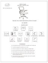
Non contractual photos and illustrations.
A B C
1
A
2
B
Push handles
Rear wheel
motorised
Footrest
Box hand
control
Armrest
Backrest
Axle of
rear wheel
C
Folding frame
Castor wheels
Cushion
Fittings seat
Legrest hanger
swing away
Backrest ttings

4
5
!
This is a warning symbol, it is essential to respect
the guidelines provided in these paragraphs in order to
avoid any injury to yourself and those around you.
This symbol indicates information which could be of
interest to you, please contact your distributor.
3.2 General Condition Check
Your wheelchair is composed of different parts and the most
important parts are referred to in this manual. We suggest that
you familiarize yourself with the following terms in order to
understand how your wheelchair works:
• The seat comprises the seat and backrest ttings, the backrest
and the armrests. Together they are designed to provide optimal
comfort;
• The swing away legrest. It comprises the support piece
between the frame and the footrest, it rotates for ease of transfers
and dismantles for transport;
• The footrest includes the adjustable rail and the footplate which
supports the foot;
• The folding frame includes the lateral mountings and the
folding system including the seat rails.
These parts constitute the frame, which is the carrying element of
the wheelchair, their overall strength has been carefully considered.
Tested at 125 kg for 380-605 mm widths and at 80 kg for 305-380
mm widths;
• The rear wheel comprises the wheel, the axle and the handrim.
The rear wheels guarantee the stability of the back and are used
for hand propulsion with the handrims;
• The castor wheel comprises the front wheel and the fork. The
castor wheels ensure front contact with the ground and determine
the direction through the orientation of the forks;
• The handbrake is a parking brake. The two handbrakes are
used to immobilise the chair during prolonged stops (in manual
propulsion);
3.3. Motor Drive Unit
• electric drive unit, 2 x 12" or 22/24" motorised wheels
• hand control box
• junction cables
• battery pack.
Legrest hanger
swing away

6
7
4. Settings
4.1. Seat
4.1.1. Seat ttings
- Standard seats:
• Nylon seat fabric with or without Velcro: the Velcro strips are
necessary for properly holding the cushion in place, ensure that it
is correctly placed on the seat.
The standard seats are not adjustable; if they become loose,
you should ask their replacement from your Distributor. Invacare
offers a range of seat cushions adapted to your needs, please
consult your Distributor.
!
Always use a fabric equipped with Velcro strips with a
cushion, this is to avoid any slippage and risk of falling!
4.1.2. Types of backrests
- Mid-height folding backrest (photo 3): in order to reduce the
volume during transport, activate the lever (B) by pulling or pushing
on it and fold the top part of the backrest.
To return to the initial position, bring back the top part to a
vertical position, it will snap back into place automatically.
!
Always check that the backrest is correctly locked into
position before the user gets in the chair in order to avoid any risk
of injury!
- 0°-30° Reclining backrests with standard 30/41/43 cm and 47/49/
51 cm heights.
They are now equipped with a new trigger handling system.
The reclining angle is easily adjustable, allowing an always
comfortable resting position.
Pull on the triggers (A) simultaneously to ensure the same angle on
the two sides and release the triggers at the chosen angle (Photo
4A).
B
3
4A
A

6
7
• Mechanical version
NOTE: Push on the backrest before activating the triggers in
order to release the locking system (automatic locking safety
mechanism) (Photo 4B)
There are 4 available reclining positions, 10° apart.
• Pneumatic version (Photos 5A and 5B). 30/41/43 cm and
47/49/51 cm Heights
The pneumatic springs provide help with lifting, always undertake
this action with the user sitting in the chair. The pneumatic springs
version may be equipped with optional pushing handles which are
height adjustable for the comfort of the attendant.
Continuous adjustment of the reclining position from 0° to 30°
!
This action should only be carried out by an attendant.
Always verify that the backrest is correctly locked in order to
ensure complete user safety.
In order to avoid any injury, keep your ngers away from any
moving parts (levers, mechanisms etc.)!
So as not to destabilize the user position, avoid activating the
levers (A) during a sideways transfer, for example!
(Photo 5B)
4B
5B
A
5A

8
9
4.1.3. Backrest ttings
- Backrests with standard cover:
If the padded backrest cover loosens, you should ask for a
replacement from your Distributor.
• Adjustable backrest tension (photo 6): it allows the adjustment of
the backrest curvature to the body shape and the position of the
user.
Lift the ap (A) and pull on one or both straps (B) and then
tighten or loosen them based on the version you have on your
chair. Each strap is adjustable independently of the others.
Reposition the ap (A).
!
Check that the Velcro strips are well positioned and holding.
Always carry out this adjustment before the user gets in the chair
to avoid any risk of injury!
4.1.4. Legrest hangers
- Standard hangers (photo 7) : they are retractable for transfers
and removable for transport.
Operate lever (A) by pushing sideways and rotate outwards or
inwards in the event of reduced space.
To return to the initial position, bring the legrest hanger back into
line, it will snap back into place automatically.
To remove the legrest hanger, simply pull upwards once you have
unlocked the system.
Carry out the operation in reverse to put it back into place
whilst keeping the unlocked position.
A
7
6
A
B

8
9
- Legrests Figure 8 & photo 9: follow the same procedure as for
the legrest hangers to retract and dismantle the legrest, operating
the trigger (A) to unlock the locking system.
Angle adjustment
Turn lever (B) with one hand while holding the legrest with the
other. Release the lever once you have reached the desired angle,
it will lock in one of the 7 positions (gure 8).
The calf cushion is retractable for transfers; its height is adjustable
by sliding after loosening the screw (C): adjust to the desired
height and rmly tighten up the screw (C). It is also adjustable
in depth: loosen the screw (D), change to the new position and
rmly tighten up the screw (D).
- Legrests (photos 10 & 11) : they are height adjustable and can
be equipped with a xed or articulated footplate (optional); the
footplate can be ipped-up for transfers. Loosen the screw (A) to
adjust to the desired height, rmly tighten up the screw after the
adjustment.
The footplate can be articulated by a toothed plate (optional),
loosen the screw (B), adjust to the desired angle and rmly
tighten up.
- Straps: to ensure a good position for the feet, two kinds of straps
are offered; the heel push strap positioned on the footplate, xed
or adjustable through Velcro strips and the calf strap afxed to the
legrest hanger and adjustable through Velcro strips.
NOTE: the standard legrest hangers and the legrests are xed by
pair on the chair; when dismantling, remember that there is a left
side and a right side!
!
Never lift the chair by the legrest hangers or the armrest! In
order to avoid any injury during folding, dismantling or adjusting
operations, keep your ngers away from any moving parts!
4.1.5. Multi-adjustable armrests (photos 12 & 13)
• To remove the armrest, simply pull it upwards, and do the
reverse to put it back in place, taking care that they are correctly
positioned.
• To adjust the height, slightly loosen the screw (A) and adjust to
the desired height using the preset adjustment holes. Firmly tighten
up.
8
C
D
A
B
9
A
B
10
11

10
11
4.1.6. Comfort Dartex seat
- Comfort Dartex seat (photo 14):
It is removable for folding the wheelchair; just lift up the seat and
put it aside, then hold the 2 chair rails and pull upwards.
Do the reverse for unfolding (see § 2.1.1).
The cover and padding of this seat is subject to wear, contact
your Distributor for any replacement.
!
Take care that the seat is well positioned on the 3 Velcro seat
strips to ensure the safety and comfort of the user. In order to
avoid any injury when folding and unfolding, keep your ngers away
from any moving parts!
- Comfort Dartex backrest (photos 15 & 15A):
Consisting of a rigid shell (A) and a preformed foam cushion (B)
afxed with Velcro, it ensures an optimal comfort. It is removable
for folding the chair: release the two buttons (C), slide the triggers
(D) inwards and release the hooks (E) from their supports. Do the
reverse to put it back in place.
• To adjust the width, slightly loosen the screw (B) and slide the
armrest to the desired width. Firmly tighten up the screw (B).
• There are two available positions for the depth according to body
shape or comfort desired by the user (positions C or D).
NOTE: the lateral protection adjustment may be necessary
according to the height chosen, unscrew the four xation screws
(E) and replace them in the new position, rmly tighten up the four
screws (E)
These armrests are xed on an adjustable carrier (in 2 parts)
which allows you to reduce the looseness and facilitates removal
during transfers, the 4 screws should be tightened or loosened (F)
according to the desired result
The armrests are xed by pair on the chair, when dismantling;
remember that there is a left side and a right side!
!
Never lift the chair by the armrests! In order to avoid any
injury during folding, dismantling or adjusting operations, keep your
ngers away from any moving parts!
F
13
12
A
B
C&D
E
D
C
A
E
B
14
15
15A

10
11
!
This action should only be carried out by the attendant.
Always check that the backrest is correctly locked in order to
ensure complete user safety.
Check that the Velcro strips of the backrest cushion are well
positioned and have a good grip.
In order to avoid any risk of injury keep your ngers away from any
moving parts!
NOTE: To clean the Dartex cover, use a soft cloth soaked in
alcohol.
- Comfort Dartex head rest (photo 16) :
It is removable by completely loosening the button (A). The height
is adjustable by slightly loosening button (A), adjust to the desired
height and tighten gently (A).
The reclining angle, depth and height of the cushion are also
adjustable in by simultaneously operating lever (B) and the screws
(C).
NOTE: take care when positioning the indexable lever so that it
isn’t in the way or could cause injury for the user or the attendant.
!
Do not adjust the headrest while the user is leaning against
it and check its attachment the backrest to avoid any risk of injury.
4.2. Frame
4.2.1. Sides
The sides or lateral support are mainly designed for receiving the
castor and rear wheels.
These wheel supports allow three (3) height positions and two
longitudinal positions:
4.2.2. Folding system
380-605 mm Widths:
It consists of two double cross-braces which integrate the seat
rails.
To fold and unfold your wheelchair, see chapter A General
Information, paragraph 2.1.
305-380 mm Widths:
It is equipped with a telescopic cross-brace (gure 17) which
offers 4 seat width adjustments from 305 to 380 mm.
The seat and backrest covers are also width adjustable.
17
A
16
C
B

12
13
The tyres are subject to wear, rough grounds and the driving
styles will also have an inuence on their life span; please
ensure their regular replacement to avoid the inconvenience of
punctures, please ask for advice from your Distributor.
4.3.2. Handrims
They are for propulsion, and are made from anodized aluminium.
!
The handrims are in permanent contact with the hands;
regularly check that they are not damaged!
4.3.3. Axles
The axles link the wheels to the frame and can be quickly
dismantled (photo 19):
- Quick-release axles (photo 20): push in button (A) and insert
the axle into the wheel hub. Position all of it in the bearing (B) of
the multi-adjustable wheel support until it locks into position.
The locking balls (C) should protrude from the bearing and there
should not be any signicant lateral looseness.
!
All of these positional changes and adjustments must be carried
out by a professional technician according to your medical prescriber;
please ask for advice from your Distributor. This information is
provided for reference only.
4.3. Rear Wheels
4.3.1. Wheels
The 22/24" (550/610 mm) rear wheels have spokes, they can be
supplied with a puncture proof tyre or band.
Repairs (photo 18) : when a tyre is punctured it needs to be removed
for repair. Remove the whole (tyre and tube) from the wheel rim,
repair or replace the inner tube, put it back in place in the tyre and
reposition the whole on the wheel rim.
Comply with the tyre pressure indicated on the side of the wheel.
NOTE: Don’t forget that in order to keep the interchangeability of
the wheelchair wheels equipped with rapid dismantling axles, the two
tyres must be inated to the same pressure.
!
The pressure indicated on
the sides of the tyre must never
be exceeded or there is a risk of
injury if the tyre were to burst!
B
C
A
20
A
B
19
18

12
13
To reduce looseness to a minimum, remove the axle and adjust
the nut with a 19 mm wrench, lock the axle with an 11 mm
spanner.
!
Regularly monitor the cleanliness of the axle and the stop
balls. To avoid any risk of falling, it is absolutely essential that the
button (A) and the stop balls are completely clear to ensure that
the rear wheels are completely locked.
The quick dismantling axle is a precision piece, avoid shocks and
clean it regularly to ensure a good performance.
4.4. Castor Wheels
4.4.1. Wheels
The castor wheels are available with a diameter of 8" (200 mm)
and a width of 2" (50 mm) or with a diameter of 7" (172 mm) and
a width of 1 3/8" (32 mm), they can be supplied with a puncture
proof tyre or band.
NOTE: Refer to paragraph 15 for ongoing maintenance.
4.4.2. Forks
Various fork positions are available based on the options chosen
for seat-to-oor height, castor and rear wheels.
If you wish to change the fork or castor or rear wheels, please
ask for advice from your Distributor.
4.5. Brakes
4.5.1. Handbrakes
The handbrakes (photo 21) are used to immobilise the chair during
prolonged stops. They cannot to be used to slow down the chair or
as a support to carry out a transfer. They must be used together.
Braking is done by pushing the handle (A) towards the front of the
wheelchair. Handle (A) folds back to facilitate transfers. Beforehand,
pull the handle upwards. Once the brakes have been activated, the
chair should not be able to move.
NOTE: the brake adjustments depends on the diameter and type
of wheels used. After repairing a at tyre or after wear of the tyre
or band, it may be necessary to adjust the brake or brakes with the
screws (B).
To carry out the adjustment, loosen the two screws (B) and slide all
of the brake until you reach between the wheel and the brake pad in
an unlocked position a value (X) as follows:
Band X = 4 mm - Tyre X = 5 mm
21
X
A
B

14
15
!
Firmly re-tighten the screw (B) after adjustment. Keep your
ngers far away from all moving parts in order to avoid any risk of
injury!
4.6. Options
4.6.1. Seat options
- Straight backrest stretcher (photo 22): it ensures that tension is
maintained for the backrest ttings and allows a better ergonomic
position for the attendant while pushing the wheelchair.
NOTE: It is foldable to fold the chair, slightly loosen button (A), pull
upwards and turn it until a vertical position is reached, along the
backrest.
To put it back in place, do the reverse and rmly tighten up button
(A) while ensuring that button (B) is tightened well.
!
Avoid lifting the chair by the stretcher! There is a risk of the
stretcher unlocking while pushing upwards.
Keep your ngers far away from any moving parts in order to avoid
any risk of injury!
4.6.2. Safety options
• Postural belt with buckle lock (photo 23): to lock the buckle, place
part (A) into part (B), to open it press on (C). Based on the user
body size, pull on one or the other of the strap extremities (D)
passing it through the two buckles (E).
It is important that both buckles (E) are used. If not there is a danger
that the belt will slip.
If the belt gets loose, it can be adjusted by tightening the strap (F)
passing it through the buckle (G).
Ensure that the user is well seated at the back of the seat and that
the pelvis is well positioned.
Position the belt under the ilium crest. Adjust the length in such a
way that a hand can t between the belt and the body of the user.
It is recommended that the belt locking mechanism is in a central
position so adjust the strap on each side.
These adjustments must be checked each time the belt is used.
B
F
C
D
A
G
E
23
22
A
B

14
15
!
The belt xation must be conform to the scheme enclosed
with each belt delivery; the belt should be mounted and adjusted
by your regular dealer.
Please be careful that the belts don’t get caught in the spokes of
the rear wheel. The postural belts must not be used as safety belts
in a car.
• Anti-tipping castor wheels with foot rest (photo 24 and gure
25) :
This version includes a support for helping to tilt.
Adjust to the desired height (while respecting the recommended
distance) by operating the button (A gure 25).
!
The recommended distance between the castor wheels and
the oor is 3-5 centimeters, this adjustment is necessary in relation
to the rear wheel position and diameter.
Operate the button (A gure 25) and adjust the desired distance
using the preset adjustment holes.
!
Ensure that the stud is well positioned in the preset adjustment
hole to avoid any risk of falling.
Never forget to fold the anti-tipping castor wheels once they are
retracted.
5. Equipment
5.1. Motor Drive Unit (photo 26)
The electric drive unit of the Esprit Action
4
NG includes the
following components:
• 2 x 12" or 22/24" motorised wheels (A)
• electronic center (B)
• the battery packs (C)
5.2. Mounting Plate (photo 27)
The mounting plates to the right and left of the wheelchair frame
are equipped with two housings (A) for the rear wheel axle and (B)
for the electrical connection which allow tting of the 2 motorised
wheels.
26
27
B
C
A
C
B
A
A
24
3 cm mini
10 mm
!
!
25
A

16
17
The bearing supports for xing the manual propulsion wheels are
positioned above (C) for e-x
®
12" and in the place of the motorised
wheels for e-x
®
22/24".
Refer to the additional e-x
®
guide paragraph 2.1 Wheel assembly and
paragraph 2.2 Removing the wheels.
5.3. Locking the Motorised Wheels
Refer to the additional e-x
®
guide paragraph 2.1 Wheel assembly and
paragraph 2.2 Removing the wheels.
5.4. Transformation Kit for Manual Propulsion (optional)
This kit allows the transformation of the powered Esprit Action
4
NG
wheelchair into a manual propulsion wheelchair.
It contains the 22/24" rear wheels (A) which are essential for the
transformation as well as two hand brakes (B). (photo 28).
Refer to paragraph 4.5.1 for adjusting the brakes.
6. ALBER e-x
®
Electronics
6.1. Electronic center
The electronic center of Esprit Action
4
NG is found in the electric
drive unit. Called the ALBER e-x
®
system, it is responsible for
controlling the movement functions.
As well as controlling the driving, ALBER e-x
®
is also responsible
for controlling the wheelchair’s electrical system.
Any system failure is indicated by a ashing light in the hand control
box (status indicator).
For more information, see the ALBER e-x
®
user manual!
7. Electrical Part
7.1. Batteries (photo 29)
All the power supply for the power wheelchair is provided by two
12V batteries (A). (12 Ah standard, 17 Ah optional).
They are housed in a box (B). To facilitate removing and
repositioning the batteries, it is possible to remove the housing box
from the wheelchair frame (self gripping strips).
7.2. 12" or 22/24" Motorised Wheels
The motorised wheels are equipped with automatic brakes.
A mechanism allows disengaging of the motors to allow the chair to
be pushed.
The motor brakes are off when the chair is pushed.
See the additional ALBER e-x
®
guide.
29
A
28
A
A

16
17
8. Mechanical Part
8.1. Hand Control Box Height Adjustment (photo 30)
• Loosen the wing nut (A) which secures the box by turning it anti-
clockwise.
• Adjust the height of the box by pulling it upwards or by pushing it
back down.
• Tighten the wing nut (A) by turning it clockwise.
8.2. Hand Control Box Retraction
• Rotate the box onto the side.
• Bring it back to its starting position. A spring will lock it in its
original position.
9. Assembling and Dismantling the 12" or 22/24"
Motorised Wheels
9.1. Dismantling the motorised wheels
See the additional ALBER e-x
®
guide, paragraph 2.1 Wheel
assembly and paragraph 2.2 Removing the wheels.
9.2. Reassembling the 12" or 22/24" Motorised Wheels
See the additional ALBER e-x
®
guide, paragraph 2.1 Wheel
assembly and paragraph 2.2 Removing the wheels.
10. Driving Guidelines / Operational safety
10.1. The First Time
Before moving the rst time with the wheelchair, familiarize
yourself with its handling and with all the driving components.
Take the time to practice all the functions and driving modes.
Use the existing retaining systems for each trip.
10.2. Comfortable Position
Before each departure, check that:
• All the control elements and accessories are easily accessible.
• the batteries are sufciently charged for the trip,
• the horn works
• the postural belt is in perfect condition.
Check the castor wheels tyre pressure
10.3. Obstacles
Esprit Action
4
NG can surmount obstacles or sidewalk height
based on to the front castor wheel dimensions, i.e. a height of 3-4
cm. Based on the chosen options your wheel chair is equipped with
different anti-tipping castor wheels with an adjustable height.
A
30

18
19
e-x
®
: Height adjustment for the anti tipping castor wheels
(photo 31 and gure 32)
Lift up the spring button (A) and choose one of the 2 available
heights, 3 or 5 cm. Make sure that the anti-tipping system is locked
in its new position
Scalamobil: See the description in the Scalamobil guide
Always reposition the anti-tipping castor wheels after
dismantling Scalamobil (risk of falling or tipping).
Driving guidelines (gure 33):
• Always approach the obstacle or sidewalk slowly and straight on
(maximum of 3 to 4 cm).
• Increase the speed just before the castor wheels or the lifting
device comes in contact with the obstacle.
• Only reduce speed after the rear wheels have also surmounted the
obstacle.
Never approach obstacles at an angle. The chair risks tipping
and only pass over obstacles with the backrest in a vertical position.
10.4. Going Uphill and downhill
Esprit Action
4
NG can securely travel uphill on inclines lower
than 5° (gure 34). There is a risk of tipping when the inclines are
steeper. Follow the course of the incline; do not travel in a zigzag
pattern.
Only go uphill or downhill with the backrest in a vertical
position and the anti-tipping castor wheels correctly secured.
Go downhill at most at 2/3 maximum speed.
Do not go uphill or downhill where the ground is rough
or slippery or if there is a risk for skidding (dampness, gravel, ice,
grass etc.).
Increased risk of tipping when getting out of the chair on a
slope.
33 34
A
3 cm mini
10 mm
!
!
31
32
/