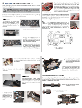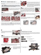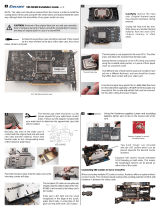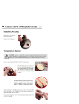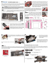
Your memory stick may include a metal heat spreader or heat sink. In order to fi t within the RAM-
35, the original heat spreader(s) must fi rst be removed. Most heat spreaders are attached with
either metal brackets, screws, or thermal tape.
Memory sticks which have heat spreaders that are soldered, riveted, or glued are not recommended
for use with the RAM-35 due to the increased possibility for damage upon disassembly.
CAUTION - Koolance’s patented Hydra-Pak™ Coolers are puncture resistant, but not puncture proof. To avoid rupturing
your Hydra-Pak™ Cooler, it is recommended to carefully cover any excessively sharp areas (for example, solder points or
corners) on your hardware with small pieces of foam or electrical tape.
3rd-party liquid cooling products are not generally supported by hardware manufacturers. Installing a Koolance liquid cooling
product is ultimately done at the user’s own risk.
!
RAM-35 Installation Guide v 1.0
Each RAM-35 will cool one DIMM memory stick in one slot. For multiple DIMM cooling, Koolance provides special connection
types for the RAM-35, discussed later.
Page 1
CAUTION - Attempting to remove a memory heat spreader can damage the memory. Make sure the heat spreader is not
soldered, riveted, or glued onto the memory stick. If attached with a tape adhesive, be very careful when removing the heat
spreader so as not to damage the memory stick.
!
Summary of Installing the RAM-35
On a typical motherboard, there is very little space between memory slots for a water block, let
alone one that channels liquid directly along both sides of each memory stick. The Koolance
RAM-35 does just that, but because of motherboard space limitations, installation of the RAM-35
becomes a special process. Here is a run-down of the steps:
1. Assess the desired liquid fl ow path through each RAM-35 block.
2. Determine the required sliding nozzles.
3. Install the sliding nozzles onto each RAM-35 block.
4. Mount the entire assembly of RAM-35 blocks and sliding nozzles over the memory sticks.
Liquid Flow Through the RAM-35
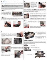
Every RAM-35 has two nozzle bases, and each base
has two nozzle sockets (on both sides) [Fig 1].
Sockets are located on both sides of the cooler,
allowing for liquid inlet and outlet nozzles to face in
either direction [Fig 2].
Internally, RAM-35 nozzle bases are connected via
two parallel Koolance Hydra-Paks liquid pouches [Fig
3]. This is important to understand when confi guring
your RAM-35 coolers to ensure proper coolant fl ow.
[Fig 2] RAM-35 Liquid Flow (Top View)
[Fig 3] RAM-35 Liquid Flow (Side View)
Rivet
Heat
Spreader
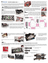
When liquid cooling only one DIMM memory stick, nozzle confi guration is very simple. The RAM-35
requires one nozzle on each base for the inlet and outlet [Fig 4]. Sockets opposite these nozzles should
remain blocked with the included plugs, forcing liquid fl ow down through the Hydra-Paks. NOTE: Basic
serial confi gurations are not recommended for systems using internal tubing diameters larger than 1/4”
(6mm) for reasons detailed below.
Connecting each RAM-35 block in series is possible, but this is not recommended for most systems.
Physical motherboard space limits the volume of liquid that can be channeled between memory sticks. To help achieve a higher
overall fl ow rate, parallel confi gurations are preferred, particularly for systems using tubing diameters larger than 1/4” (6mm) ID.
Parallel confi gurations require at least two RAM-35 water blocks.
Using One RAM-35 Cooler and Serial vs. Parallel
Nozzle Bases
Nozzle Sockets
(With Plugs)
[Fig 1]
[Fig 4] Installed Nozzles
www.koolance.com


