Page is loading ...

Instruction Sheet
PHONE: (360) 734-1540 • www.southbendlathe.com
MODEL SB1224
12" 3-JAW SCROLL CHUCK
Copyright © April, 2011 by South Bend Lathe Co.
WARNING: No portion of this manual may be reproduced without written approval.
#CR13937 Printed in Taiwan
Mounting Type ......... Direct Mount D1-8 Camlock
Chuck Outer Diameter ...................12.2" (310mm)
Chuck Bore Diameter .....................4.05" (103mm)
OD Clamping Range ...... 0.12"–4.65" (15 –300mm)
ID Clamping Range ....... 1.78"–4.61" (90–290mm)
Static Clamping Force .............................. 9890 lbs
Maximum Chuck Key Torque .................137 ft/lbs
*Maximum Speed .................................. 1800 RPM
Chuck Jaw M12 Cap Screw Torque .......78.8 ft/lbs
Rear Chuck M12 Cap Screw Torque ......78.8 ft/lbs
Chuck Weight .............................................. 105 lbs
Country of Origin ....................................... Taiwan
* Even if a tailstock and steady rest are used,
the maximum speed rating may not be
SAFELY reached with certain workpieces.
The workpiece must be balanced and
appropriately sized for the chuck and lathe,
and the chuck must be properly maintained
to achieve maximum clamping force. As
spindle speeds increase, centrifugal force
also increases. If centrifugal force becomes
too great, the workpiece can be thrown from
the chuck with deadly force. Always use good
judgment with each setup!
Specifications
Introduction
Incorrect use of this tool
can result in death or
serious injury. For your
own safety, read and
understand this entire
document before using.
This chuck uses a direct-mount camlock system
to attach to the spindle. Direct-mount chucks
provide a number of advantages over chucks that
require a back plate for mounting.
The main benefit is a larger maximum working
area between the chuck jaws and tailstock. The
increased space is created by the absence of a
back plate between the chuck and spindle.
Another benefit is that direct-mount chucks
require less initial setup time because the
machinist is not required to machine a back plate
to fit the chuck.
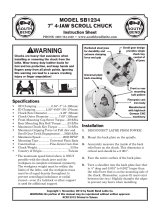
Figure 1. Main features of this chuck.
Threaded
Pinion
Retaining
Pins
Direct
Mount
Back
Camlock
Studs
Reversible Top Jaws
Two-Piece Jaws
Two-Piece
Center
Split
Chuck
Rear
Chuck Cap
Screws

Chuck Safety
Trained Operators Only. Using a chuck
incorrectly can result in workpieces coming
loose at high speeds and striking the operator
or bystanders with deadly force. To reduce the
risk of this hazard, read and understand this
document and seek additional training from an
experienced chuck user before using this chuck.
Using Correct Equipment. Many workpieces can
only be safely turned in a lathe if additional
support equipment, such as a tailstock or steady
rest, is used. If the operation is too hazardous
to be completed with the lathe or existing
equipment, the operator must have enough
experience to know when to use a different
machine or find a safer way.
Disconnect Power. Serious entanglement or
impact injuries could occur if the lathe is started
while you are adjusting, servicing, or installing
the chuck. Always disconnect the lathe from
power before performing these procedures.
Handling Chucks. Chucks are heavy and
awkward to hold, especially if they are oily.
A dropped chuck can result in amputation
or crushing injuries and equipment damage.
Always use some kind of chuck cradle, protective
device, or lifting assistance when installing and
removing chucks.
Chuck Key Safety. A chuck key left in the chuck
can become a dangerous projectile when the
lathe is started. Always remove the chuck key
after using it. Develop a habit of not taking your
hand off of a chuck key unless it is removed from
the chuck.
Proper Maintenance.
All chucks must be properly
maintained and lubricated to achieve maximum
clamping force and withstand the rigors of
centrifugal force. To reduce the risk of a thrown
workpiece, follow all maintenance intervals and
instructions in this document.
Speed Rates. Fast spindle speeds increase the
centrifugal force on the chuck and workpiece.
Excessive centrifugal force can cause the chuck
to lose its grip and throw a workpiece, or cause a
chuck to break apart with deadly consequences.
Use slow spindle speeds when ever possible,
take all safety precautions, and double check
the workpiece for proper clamping and support
before starting the lathe.
Chuck Capacity. Avoid exceeding the capacity of
the chuck by clamping an oversized workpiece.
If the workpiece is too large to safely clamp
with the chuck, use a faceplate or a larger chuck
if possible. Otherwise, the workpiece could
be thrown from the lathe during operation,
resulting in serious impact injury or death.
Clamping Force. Inadequate clamping force can
lead to the workpiece being thrown from the
chuck and striking the operator or bystanders.
Maximum clamping force is achieved when the
chuck is properly maintained and lubricated, all
jaws are fully engaged with the workpiece, and
the maximum chuck clamping diameter is not
exceeded.
Entanglement. Entanglement with a rotating
chuck can lead to death, amputation, broken
bones, or other serious injury. Never attempt to
slow or stop the lathe chuck by hand, and always
roll up long sleeves, tie back long hair, and
remove any jewelry or loose apparel BEFORE
operating.
Long Stock.
Long stock can suddenly whip
violently when the lathe is started, or without
warning during lathe operations causing death
or serious impact injury. Always use additional
support with any workpiece that extends from
the chuck or the end of the outboard spindle
more than three times the workpiece diameter.
-2-
Mfg. Since 1/11
Model SB1224
INSTRUCTIONS

Chuck Installation &
Removal Devices
Because chucks are heavy and often awkward to
hold, some kind of lifting, support, or protective
device should be used during installation or
removal. The weight and size of the chuck will
determine the appropriate device to use (refer to
the following figure for examples).
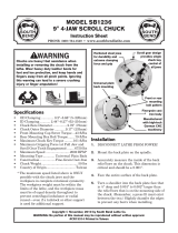
Pre-Threaded Hole
for Lifting Eye
Way Slot
Jaw Slot
Plywood & 2x4
Chuck Cradle
Plywood Chuck Cradle
(Straight Cuts)
Plywood Chuck Cradle
(Curved Cuts)
Fabricated Steel
Lifting Hook
Solid Block
Chuck Cradle
Plywood Protection
Plate for Chucks
Installed by Hand
SMALL, LIGHTWEIGHT CHUCKS
MEDIUM-SIZE, HEAVY CHUCKS
LARGE, VERY HEAVY CHUCKS
Figure 3. Examples of common devices used during
chuck installation and removal.
Camlock Stud
Installation
This section provides information about how to
install and adjust the camlock studs so the chuck
properly mounts to the spindle.
Note: You can skip this section if the camlock
studs are already installed.
Figure 2. Camlock stud installation.
Cap
Screw
Datum Line
Flush with Chuck
Surface
Alignment
Groove
To install the camlock studs:
1. Lightly oil the threads of each stud.
2. Thread the studs into the chuck until the
datum line is flush with or just above the
surface of the chuck, and the alignment
groove is positioned over the hole.
3. Install a cap screw in the hole next to each
stud. These cap screws prevent the studs
from rotating so they properly engage with
the camlock during installation.
Note: It is normal for studs to have a small
amount of play or looseness after installing
and tightening the cap screws.
A dropped chuck can cause amputation,
serious crushing injuries, or property damage.
Always use a lifting, support, or protective
device to reduce this risk when installing or
removing a chuck.
Mfg. Since 1/11 Model SB1224
-3-
INSTRUCTIONS

Chuck Installation
Figure 4. Inserting camlock studs into spindle bores.
INCORRECTCORRECT
5. Incrementally tighten the camlocks in a
criss-cross or star pattern to ensure that the
chuck seats evenly against the spindle.
6. When the chuck is fully seated and all the
camlocks are tight, verify that the cam line
is between the two "V" marks on the spindle
nose, as shown in the following figure.
— If the cam line is NOT between the "V"
marks when the camlock is tight, the stud
may be installed at the incorrect height.
To fix this, adjust the stud height as
shown in the following figure. Make sure
to re-install the stud cap screw afterward.
— If adjusting stud height does not correct
the problem, try swapping stud positions
on the chuck.
Figure 5. Cam line positioned between the "V" marks
after the camlocks are fully tightened.
Camlock between “V”s
Figure 6. Correcting an improperly installed stud.
Stud Too High:
Turn In
One-Turn
Stud Too Low:
Turn Out
One-Turn
INCORRECT INCORRECT
To install the chuck:
1. DISCONNECT LATHE FROM POWER!
2. Use an appropriate lifting, support, or
protective device to protect the ways and
support the chuck.
3. Clean and lightly oil the camlock studs, then
thoroughly clean the mating surfaces of the
spindle and chuck.
4. Install the chuck by inserting the camlock
studs straight into the spindle cam holes.
Important: Avoid inserting the studs by
pivoting them in from an angle or rotating
the spindle. This can damage studs or bores.
To ensure accurate work, it is extremely
important to make sure the spindle nose and
chuck mating surfaces/tapers are clean. Even
a small amount of lint or debris can affect
accuracy.
The chuck is properly installed when all
camlocks are tight, the spindle and chuck tapers
firmly lock together, and the back of chuck is
firmly seated against the face of the spindle all
the way around—without any gaps.
-4-
Mfg. Since 1/11
Model SB1224
INSTRUCTIONS

7. Verify that the chuck fits the spindle
properly by checking for any gaps between
the mating surfaces.
— If there are no gaps, proceed to Step 9.
— If there is a gap, remove the chuck, re-
clean the mating surfaces carefully, and
re-install. If the problem persists, refer to
Troubleshooting.
8. Verify that the chuck/spindle tapers
are seating firmly together by removing
the chuck, per the Chuck Removal
instructions, and paying close attention to
how easily the tapers release.
— If it was necessary to bump the chuck or
use a mallet to release the tapers, then
they are seating together properly.
— If the tapers released easily with little
intervention, they are not seating together
firmly as required. Remove the chuck, re-
clean the mating surfaces carefully, and
re-install. If the problem persists, refer to
Troubleshooting.
To remove the chuck:
1. DISCONNECT LATHE FROM POWER!
2. Use an appropriate lifting, support, or
protective device to protect the ways and
support the chuck.
3. Loosen the camlocks by turning the key
counterclockwise until the cam lines are
aligned with the mark on the spindle nose.
Tip: Camlocks can become very tight. A cheater
pipe may be used as a last resort to add
leverage when loosening. After loosening,
you may need to wiggle the chuck key in the
camlock to fully disengage the stud.
Figure 8. Camlock is fully loosened when the cam line
is aligned with the spindle mark.
Cam line aligned with spindle mark
4. Using a dead blow hammer or other
soft mallet, lightly tap around the outer
circumference of the chuck body to loosen it
from the spindle.
5. Remove the chuck from the spindle, using
a light rocking motion to carefully slide the
studs out of the bores.
— If the chuck does not immediately come
off, rotate it approximately 60˚ and tap
it again. Make sure all the marks on the
cams and spindle are in proper alignment
for removal.
Chuck Removal
Figure 7. Registration mark locations.
Camlock
Spindle
2-Piece
Direct Mount
Camlock Chuck
Marks
for Chuck
Reassembly
Chuck
Halves
Spindle & Chuck
Registration Marks
Registration Marks
Lightly stamp registration marks across the
mating seams of chuck components. These marks
will help you re-install the chuck in the same
position after removal, which ensures consistent
chuck balance and turning results, and allows
the same camlocks and studs to operate together
for consistent locking and unlocking.
Mfg. Since 1/11 Model SB1224
-5-
INSTRUCTIONS

Scroll Chuck Clamping
This scroll-type chuck has an internal scroll-gear
that moves all jaws in unison when adjusted with
the chuck key. This chuck will hold cylindrical
parts on-center with the axis of spindle rotation
and can be rotated at high speeds if the
workpiece is properly clamped and balanced.
Never mix jaw types or positions to
accommodate an odd-shaped workpiece.
The chuck will spin out of balance and
may throw the workpiece! Instead, use an
independent jaw chuck or a faceplate.
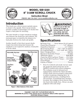
Figure 9. Jaw selection and workpiece holding.
Insufficient
Jaw Clamping
Unstable
Workpiece
Bar Stock
Inside
Safer
UseJaw
Cylinder
Unsafe Jaw Position
Poor Scroll
Gear Engagement
Inside
Safer
UseJaw
Shallow
Bar Stock
InsideUnsafe
UseJaw
Poor Scroll Gear Engagement
Unsafe Jaw Position and
Outside
Safer
UseJaw
Poor Scroll Gear Engagement
Unsafe Jaw Position and
Poor
Unstable
Workpiece
Shallow
Bar Stock
Outside
Safer
UseJaw
Grip
This chuck has 2-piece jaws that consist of a
top jaw and a master jaw. The top jaw can be
removed, rotated 180°, and re-installed in the
reverse position for additional work-holding
options. When reversing the top jaws, always
keep them matched with their original master
jaw to ensure the best fit.
To reverse 2-piece jaws:
1. DISCONNECT MACHINE FROM POWER!
2. Remove the cap screws that secure the top
jaw to the master (bottom) jaw.
3. Remove the top jaw, rotate it 180°, then re-
install it with the longest cap screw in the
tallest portion of the jaw.
4. Repeat Steps 2–3 with each remaining jaw
(we recommend only reversing one jaw at a
time to keep all original parts together).
Figure 10. Reversing the chuck jaws.
Master Jaw
Rotate Top
Jaw 180º
Long Cap ScrewShort Cap Screw
Chuck Jaw Reversal
Remove all tools before
turning lathe ON. Thrown
tools can cause serious
injury or death to operator
or bystanders.
-6-
Mfg. Since 1/11
Model SB1224
INSTRUCTIONS

Maintenance
A chuck can only achieve its maximum clamping
force when its internal components are clean and
well lubricated.
During operation, centrifugal force displaces
and thins the lubricant inside the chuck, forcing
it out over time. If the chuck is exposed to
cutting fluid, this process happens even faster. If
maintenance is not followed daily, the chuck will
lose its internal lubrication and collect cutting
fluid sludge, rust, and metal chips—which can
cut the maximum chuck clamping force in half!
A chuck with reduced clamping force has a much
higher risk of losing its grip during operation and
throwing the workpiece with deadly force.
Items Needed Qty
Hex Wrench Set (Metric) ...................................... 1
High Resolution Caliper 8" ...................................1
Crocus Cloth & Wire Brush ............................ 1 Ea
Diamond Hone or Dressing Stones ...........Various
Files & Thread Chasing Tools ................... Various
Mineral Spirits and Cotton Rags ...... As Required
Calibrated Torque Wrench ..................................1
Stiff 1" Brush for Applying Grease ......................1
Oil ........................ South Bend Way Oil #SB1365
Chuck Grease ............................. Bison #7-799-025
(or Equiv. Moly-Disulphide Chuck Grease)
Chuck Service
• Check/correctloosemountingbolts.
• Use a vacuum, rag, or brush to clean the
chuck after use.
• Wipedowntheoutsideofthechuckwitha
light machine oil or way oil.
Daily Maintenance
Regular Lubrication
Recommended Lubricant
Chuck Grease ............................. Bison #7-799-025
(or Equiv. Moly-Disulphide Chuck Grease)
Oil ........................ South Bend Way Oil #SB1365
Lubricate the scroll thread and jaw slides
regularly, using either chuck grease or way oil.
To lubricate, remove and clean the jaws, clean
chips off the scroll gear if necessary, then re-
install the jaws and apply lubricant to the scroll
gear and jaw sliding surfaces. Move the jaws in
and out to distribute the lubricant.
Chuck grease provides superior lubrication and
clamping force; its drawback is that chips easily
stick to it and get drawn into the chuck, leading
to binding and reduced clamping force.
Way oil is a good alternative lubricant to reduce
the amount of chips that stick to the chuck;
its drawback is a reduction of clamping force,
making it a poor choice for heavy clamping loads.
To avoid damage when servicing the chuck:
• Onlyclampchuckpartsinaviseequipped
withsoftjawsorwood/aluminumblocks.
• Neveruseanopenameonchuckparts!
• Neverstrikethechuckwithasteelhammer.
Insteaduseabrasshammerorsoftmallet.
• Neverapplyforcetostuckcomponentsif
youareunsureabouthowtheyarefastened
together.Refertotheinstructions.
• Whenseparatingorremovingmated
components,donotattempttopryorwedge
themapart.Instead,patientlytapthemat
variouslocationswithabrasshammeror
malletwhilerotatingandpullingonthem.
• Ifthescrollgearorretainerisstuck,soak
partsinpenetratingoilorsolvent(overnight
ifneeded)tobreakdowngreasesuction,then
carefullyrotate,lift,andtapitloose.
Properchuckservicerequiresfulldisassembly,
cleaning,andlubrication.Performthisservice
everysixmonths,ormorefrequentlyifthechuck
isexposedtodirtyworkenvironments,heavy
workloads,orcuttingfluid.
Mfg. Since 1/11 Model SB1224
-7-
INSTRUCTIONS

Cleaning
When cleaning chuck components, make sure to
remove all grease, sludge, and metal particles
using a brush and clear-type mineral spirits
or standard paint thinner. Avoid using white-
colored mineral spirits, acetone, brake parts
cleaner, gasoline, or acids. If an incorrect solvent
is used, stains, additives, acids, or contaminants
can be left behind as a corrosive coating. After
cleaning and drying parts, be sure to wipe down
parts with an oiled rag to prevent rust.
Light rust can be removed in a blast cabinet
with soda blasting media. For heavy rust, have
the chuck components “hot tanked” at a local
automotive machine shop (remove all non-ferrous
items first or they may dissolve).
Inspect all components carefully for burrs, wear,
scoring, bent parts, cracks, and thread damage.
Carefully inspect the chuck jaw clamping surface
for tapered wear from front to back. For minor
wear, jaw regrinding may be more economical
than jaw replacement. If the taper is heavy,
or grip, or work holding accuracy is a problem,
chuck replacement is likely required.
Burrs, dings, flakes, high spots, or galled
surfaces can usually be removed by lightly
dressing them away with diamond lapping
boards or honing stones with lapping oil. Be
sure not to change part dimensions while
dressing surfaces. Thread damage can usually be
corrected with files and thread chasing tools.
If any parts are overly worn, bent, cracked,
or otherwise damaged, they must be replaced
(if available). Never attempt to repair chuck
components by welding them. If damaged parts
are unavailable, replace the chuck. Continuing
to use a chuck with damaged components will
increase the risk of accidental death or serious
injury. Do not risk it!
If replacing fasteners, make sure to use the same
hardness or grade as the original fasteners that
were installed on the chuck.
Reassembly
Brush all internal chuck components with a
generous coat of chuck grease, but do not pack
the chuck full of grease. Re-assemble components
in the reverse order of disassembly. Make sure to
follow the Chuck Jaw Installation instructions
to ensure that the jaws are installed correctly.
Make sure you only use approved chuck
lubricants. Some lubricants can stain your
chuck or have unintended reactions with cutting
fluid, which will destroy their ability to properly
lubricate the chuck.
To avoid stripping threads or cracking a casting,
never use fasteners to draw components together
and avoid using impact tools. Instead, be patient
and properly seat the mating parts, then use
hand tools and a recently calibrated torque
wrench to tighten fasteners.
Note: Some Features &
Fasteners are Excluded
for Clarity
Rear
Chuck Body
and Fasteners
Scroll Gear
Pinion
and
Retaining Pin
Front
Chuck Body
Figure 11. Chuck components.
Inspection & DressingDisassembly
1. Verify that registration marks have been
made on the chuck and spindle. (Refer to
Registration Marks section for details.)
2. Inspect the jaws and their slots to make sure
they have matching numbers or marks. If
none are found, stamp or scribe your own
before continuing. (During re-assembly, jaws
must be installed in the same slots.)
3. Use the chuck key to back out and remove
the chuck jaws.
4. Unthread all chuck fasteners and separate
the chuck halves, then remove the remaining
chuck components to completely disassemble
the chuck (see below).
-8-
Mfg. Since 1/11
Model SB1224
INSTRUCTIONS

When installing the jaws on a scroll chuck, it
is important to make sure they are installed
correctly. Incorrect installation will result in
jaws that do not converge evenly and are unable
to securely clamp a workpiece.
To install chuck jaws:
1. Rotate the chuck key clockwise until you
see the tip of the scroll-gear lead thread just
begin to enter jaw guide #1.
Figure 12. Installing jaw #1.
Lead Thread
1
1
(Locations
May Vary)
2. Insert jaw #1 into jaw guide #1, and hold the
jaw against the scroll-gear.
3. Rotate the chuck key clockwise one turn to
engage the tip of the scroll-gear lead thread
into the jaw. Pull the jaw; it should be locked
into the jaw guide.
4. Install the remaining jaws in numerical
order, in the same manner.
— If installed correctly, the jaws will
converge evenly at the center of the chuck.
— If the jaws do not converge evenly, remove
them. Make sure the numbers of the jaws
and jaw guides match, then re-install the
jaws and make sure each one engages
with the scroll-gear lead thread during its
first rotation.
Chuck Jaw Installation
Mfg. Since 1/11 Model SB1224
-9-
INSTRUCTIONS

Symptom Possible Cause Possible Solution
Chuck mounts
or seats
incorrectly;
gap exists
between chuck
and spindle;
chuck vibrates
during
operation
without a
workpiece
installed.
1.
Chuck is loose or cocked on spindle; gap
between spindle/chuck mating.
1.
Remove chuck then clean and dress all mating
surfaces of spindle & chuck.
2.
Chuck is too large for lathe.
2.
Install smaller lathe chuck so spindle and bearings
will not become overloaded and vibrate.
3.
Lathe spindle is loose.
3.
Check and adjust lathe spindle end-play and
bearing preload.
4.
Camlock studs are at fault.
4.
Remove chuck and inspect/adjust/replace camlock
studs for wear or damage as required. Re-install
chuck with registration marks aligned.
5.
Lathe spindle is loose.
5.
Check and adjust lathe spindle end-play and
bearing preload. Adjust as required.
6.
Poor chuck/spindle taper fit causes
radial or axil runout from chuck shifting
when camlocks are tightened.
6.
Isolate component at fault by installing a different
chuck. If problem persists, lathe spindle may be at
fault. If problem goes away, chuck may be at fault.
7.
Chuck is distorted or cracked.
7.
Replace chuck.
The chuck key
is hard to turn,
or it binds
at some jaw
locations.
1.
Jaws poorly positioned.
1.
Re-install jaws in correct order and position.
2.
Lack of lubrication; rust, burrs, metal
chips, or contaminants inside chuck.
2.
Disassemble, de-burr, clean, and re-lubricate chuck
with chuck grease.
3.
Jaw guides, scroll gear, or pinion
distorted, worn, or broken.
3.
Replace damaged parts, or replace chuck.
The workpiece
slips in the
jaws.
1.
Workpiece requires additional support
in addition to chuck jaws.
1.
Use tailstock, rests, and outboard spindle support.
Use slower spindle speed.
2.
Incorrect jaw or workpiece clamping
position.
2.
Re-position jaws and workpiece for maximum scroll
gear and jaw engagement. Verify that workpiece is
not too large or heavy for chuck.
3.
Two-piece jaw is loose; top jaw
improperly seated in master jaw.
3.
Remove jaws, clean mounting surfaces, and re-
install with the correct cap screw torque.
4.
Insufficient pinion and scroll gear
torque.
4.
Lubricate chuck, and re-tighten the chuck key.
5.
Jaws or jaw screws bind before full
clamping force is achieved.
5.
Service the chuck as described in this document.
6.
Cutting overload.
6.
Reduce cutting depth or feed rate.
7.
Jaw teeth worn; 2-piece jaw is loose.
7.
Have jaws reground, replace jaws, or replace chuck.
Troubleshooting
Workpiece
has runout;
clamping
accuracy or
repeatability is
poor; turning
results are
poor.
1.
Workpiece is too long for jaw clamping
only.
1.
Use tailstock, rests, and outboard spindle support;
use slower spindle speeds.
2.
Workpiece is improperly clamped or is
misaligned.
2.
Remove jaws, then clean, de-burr, and re-install.
3.
Jaws are positioned in the wrong jaw
guides.
3.
Re-install jaws in their correct guides.
4.
Top jaws are loose or improperly seated
in their master jaws.
4.
Remove jaws, clean jaw teeth and guides, then re-
install jaws using the correct torque for fasteners.
5.
Chuck is loose; mounting is off center or
improperly seated.
5.
Refer to troubleshooting for chuck mounting
incorrectly.
6.
Lathe spindle, tailstock, or cross slide is
misaligned with lathe bed.
6.
Align lathe components.
7.
Lathe bed is twisted.
7.
Place shims under lathe to level bed ways.
-10-
Mfg. Since 1/11
Model SB1224
INSTRUCTIONS

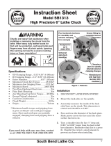
Please Note: We included this parts breakdown for service purposes only. Since many of the parts shown are machined to
each individual chuck, they may not be available as replacement items.
Parts Breakdown
2
7
9
15
8
12
10
6
13
14
3
4
1
16
5
17
REF PART # DESCRIPTION REF PART # DESCRIPTION
1 PSB1224001 FRONT CHUCK BODY 9 PCAP171M CAMLOCK STUD
2 PSB1224002 SCROLL GEAR 10 PCAP65M CAP SCREW M10-1.5 X 70
3 PSB1224003 TOP JAW 12 PCAP73M CAP SCREW M12-1.75 X 50
4 PSB1224004 MASTER JAW 13 PAW10M HEX WRENCH 10MM
5 PSB1224005 PINION GEAR 14 PCAP36M CAP SCREW M12-1.75 X 25
6 PSB1224006 REAR CHUCK BODY 15 PCAP155M CAP SCREW M8-1.25 X 14
7 PSB1224007 CHUCK WRENCH 16 PSB1224016 COMPRESSION SPRING
8 PSB1224008 PINION RETAINING PIN 17 PSB1224017 GREASE FITTING
Mfg. Since 1/11 Model SB1224
-11-
INSTRUCTIONS

Other Great Items from South Bend
Quick Change Tool Post Sets
SB1405
Set 1 for 9" - 12" Swing Lathe
SB1406
Set 2 for 10" - 110" Swing Lathe
SB1407
Set 3 for 13" - 18" Swing Lathe
SB1408
Set 4 for 14" - 20" Swing Lathe
These are probably the smoothest and hardest
locking tool posts on the market today. Wedge-
locking design prevents tool holder from shifting
during the heaviest of cuts. The unique and
ergonomic locking handle was designed by
South Bend engineers to prevent fatigue during
frequent tool changes.
Set Includes:
• Turning Tool Holder
• Turing/Boring Holder
• Boring Bar Holder
• Parting Blade Holder
• Knurl/Facing Holder
• Tool Post w/ T-nut
Way Oil
SB1365
Way Oil (12 oz)
Engineered for the high
pressure exerted on horizontal
or vertical ways and slides.
Protects against rust and
corrosion. Ensures stick-
free, smooth motion which
maximizes finishes and
extends the life of your
machine. Won’t gum up! 12 oz.
AMGA#2 (ISO 68 Equivalent)
South Bend Shop Clocks
SB1298—SBL Bench Lathe Shop Clock
SB1299—SBL Toolroom Lathe Shop Clock
SB1300—SBL Lathe with Man
These fine traditional shop clocks are constructed
with a metal antique-finished frame. They are
easy to read from a distance and measure 14"
in diameter. Pictures just don't do them justice.
They are very nice quality clocks and perfect for
the South Bend Lathe aficionado.
SB1298 SB1299
SB1300
4-Jaw Independent Chucks
SB1232—14" 4-Jaw Independent Direct
Mount D1-8 Chuck
SB1214—12" 4-Jaw Independent Plain Back
Chuck
SB1404—12
1
⁄2" Backplate D1-8 (for SB1214)
South Bend chucks are made for high precision
work with tight tolerances to satisfy the most
demanding machinists out there! Constructed of
fine grain cast iron with a super finish.
SB1232
SB1404
SB1214
-12-
Mfg. Since 1/11
Model SB1224
INSTRUCTIONS
/