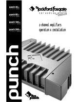
Rockford Fosgate 100X2 User manual

Category
Car audio amplifiers
Type
User manual
®®
DSM
2-CHANNEL AMPLIFIER
OWNER'S MANUAL
Dear Customer,
Congratulations on your purchase of the world's finest brand of car audio
amplifiers. At Rockford Fosgate we are committed to musical reproduction at
its best, and we are pleased you chose our product. Through years of engineer-
ing expertise, hand craftsmanship and critical testing procedures, we have
created a wide range of products that reproduce music with all the clarity and
richness you deserve.
For maximum performance we recommend you have your new Rockford
Fosgate product installed by an Authorized Rockford Fosgate Dealer, as we
provide specialized training through Rockford Technical Training Institute
(RTTI). Please read your warranty and retain your receipt and original carton
for possible future use.
To add the finishing touch to your new Rockford Fosgate image order your
Rockford accessories, which include everything from T-shirts and jackets to
hats and sunglasses.
To get a free brochure on Rockford Fosgate products and Rockford accessories,
please call 602-967-3565 or FAX 602-967-8132. In Canada, call Korbon
Trading at 905-567-1929. For International orders, FAX +001-1-602-967-
8132 or call +001-1-602-967-3565.
The serial number can be found on the outside of the box. Please record it in
the space provided below as your permanent record. This will become useful
in recovering your amplifier if it is ever stolen and serve as verification of your
factory warranty.
Serial Number: ___________________
Model Number: ___________________
PRACTICE SAFE SOUND™
CONTINUOUS EXPOSURE TO SOUND PRESSURE LEVELS OVER
100dB MAY CAUSE PERMANENT HEARING LOSS. HIGH POWERED
AUTOSOUND SYSTEMS MAY PRODUCE SOUND PRESSURE LEVELS
WELL OVER 130dB. USE COMMON SENSE AND PRACTICE SAFE
SOUND.
TABLE OF CONTENTS
Specifications ................................................................................... 1
Punch Accessory Pack .................................................................... 3
Introduction ...................................................................................... 4
Notes on Internal Circuitry ........................................................... 4
Controls and Features...................................................................... 6
Top View of Amplifier and End Caps .......................................... 6
Front View of Power Side ............................................................ 7
Side View of Input Side ............................................................... 8
Installation Considerations ............................................................... 9
Tools Needed ............................................................................ 10
Battery and Charging ..................................................................... 10
Mounting and Location ................................................................... 10
Trunk Mounting ......................................................................... 10
Passenger Compartment Mounting .......................................... 11
Wiring the Punch ............................................................................ 11
Power ........................................................................................ 11
Ground ...................................................................................... 11
Remote Turn-on ........................................................................ 11
Input .......................................................................................... 12
Speakers ................................................................................... 12
Mono Configuration ................................................................... 12
Passive Crossover Impedance ................................................. 13
Table of Component Values........................................................... 15
Wiring Diagrams............................................................................. 16
Troubleshooting ............................................................................. 19
Dynamic Power Measurements ..................................................... 24
Warranty Information...................................................................... 27
L'Installation / Câblage ................................................................... 28
Installation / Verkabeluug ............................................................... 30
La Instalacíon / Cableado .............................................................. 32
Installazione / Elettriche ................................................................. 34
1
SPECIFICATIONS
PUNCH 40DSM PUNCH 60DSM PUNCH 100DSM PUNCH 200DSM
Dynamic Power Rating (IHF-202 Standard) - Measured at 14.4 Volts
1
Mono into a 4 Load 160 Watts 260 Watts 420 Watts 500 Watts
Per channel into a 2 Load 75 Watts 130 Watts 200 Watts 240 Watts
Per channel into a 4 Load 40 Watts 80 Watts 110 Watts 150 Watts
Continuous Power Rating (IASCA Standard) - Measured at 11.6 Battery Volts
RMS continuous power per channel,
both channels driven into a 4 load 20 Watts 30 Watts 50 Watts 100 Watts
from 20 to 20,000 Hz with less than (@ 11.9
0.05% Total Harmonic Distortion (THD) Battery Volts)
RMS continuous power per channel,
both channels driven into a 2 load 40 Watts 60 Watts 100 Watts 200 Watts
from 20 to 20,000 Hz, with less than (@ 11.9
0.1% Total Harmonic Distortion (THD) Battery Volts)
RMS continuous power mono into a
4 load from 20 to 20,000 Hz, with 80 Watts 120 Watts 200 Watts 400 Watts
less than 0.1% Total Harmonic (@ 11.9
Distortion (THD) Battery Volts)
Signal-to-Noise Ratio Over 110dB A-weighted
1
See Appendix A - Dynamic Power Measurements for information on these specifications.
2
PUNCH 40DSM PUNCH 60DSM PUNCH 100DSM PUNCH 200DSM
Dimensions 9-5/8" (24.4cm) W 9-5/8" (24.4cm) W 9-5/8" (24.4cm) W 9-5/8" (24.4cm) W
9-5/8" (24.4cm) L 10-5/8" (27.0cm) L 11-5/8" (29.5cm) L 12-5/8" (32.0cm) L
2-5/8" ( 6.6cm) H 2-5/8" ( 6.6cm) H 2-5/8" ( 6.6cm) H 2-5/8" ( 6.6cm) H
Bandwidth 15Hz to 100kHz ±3dB
Damping Factor @ 4 At output connector - Over 200
Frequency Response 20Hz to 20kHz ±1.0dB / 10Hz to 100kHz ±3dB
Slew Factor Over 5
IM Distortion (IHF) Less than 0.05%
Input Gain Variable from 40dB to 14dB (250mV - 1 Volt)
25dB 26.8dB 29dB 32dB
The above figures are factory preset and are correct for 500 m
V rated source units.
Protection Internal analog-computer output protection circuitry limits power in case of
overload. Thermal switch shuts down the amplifier in case of overheating.
Battery Fusing Rates 20 Amps 30 Amps 40 Amps 50 Amps
(External to Amplifier)
Fuse Type ATC ATC ATC AGU
Equalization Bass: +18dB Maximum at 45Hz
Treble: +12dB Maximum at 20kHz
Input Impedance 20k ohms
Specifications subject to change without notice.
PUNCH ACCESSORY PACK
3
17'
(518.16cm)
Red Power
Wire
Punch
Owner's
Manual
Punch
Verification
Certificate
Power Fuse Holder
with Fuse for Punch
40, 60, and 100
Power Fuse Holder
with fuse for Punch 200
Hex Head and
Mounting Screws
Remote Turn-on Wire
Connector Plug
Power Ring
Terminals
12' (365.76cm)
Blue Remote
Turn-on Wire
1.5' (45.72cm) Black
Grounding Wire
4
INTRODUCTION
This manual provides information on the features, instal-
lation, and operation of the Punch 2-channel Amplifiers.
We suggest you save this manual for future reference.
We strongly recommend you have your Authorized Rock-
ford Fosgate Dealer and Service Center install the new
Punch amplifier. If you do choose to install the amplifier
yourself, please be sure to read the entire manual before
beginning.
The Rockford Punch 40DSM, 60DSM, 100DSM and
200DSM automotive stereo power amplifiers provide
state-of-the-art sound in cars, vans, boats, or wherever a
high current 12 volt power source is available.
Discrete Surface Mount (DSM) technology is utilized in
the crafting of all our Punch amplifiers. This process
provides greater ruggedness and consistency of both
components and layout. Already used heavily in aero-
space, industrial and automotive applications, this tech-
nology is also highly advantageous in the hostile automo-
tive environment.
The Punch adjustable input circuits are designed to
match almost any music source. The amplifiers will drive
most normal speaker types.
Internal circuitry in the Punch amplifier prevents damage
due to speaker terminal shorts. The Punch incorporates
internal battery line filtering and extensive noise preven-
tion circuitry.
The Punch Equalization circuit is best utilized and de-
signed to compensate for the acoustic inadequacies of
the automotive environment. This patented circuitry will
correct for the poor bass response and natural high
frequency roll-off inherent in the world of automotive
stereo. The result is full-range sound without the unpleas-
ant changes in the mid-range sound produced by most
tone control and equalizer circuits.
Notes on
Internal
Circuitry
5
High powered audio amplifiers must always address the
problem of power device reliability. In particular, load fault
conditions can easily destroy an amplifier that is not
carefully designed. Rockford Fosgate has answered this
problem with the development of Real Time Power Pro-
tection (RTPP).
The RTPP circuits protect the Punch amplifiers by multi-
plying output device voltage and current values to obtain
approximate instantaneous device power. This instanta-
neous power calculation is then processed through a time
constant closely modeling the device heating time. If the
resulting modeled junction temperature exceeds a set
threshold, gate drive to the output devices is limited.
To get a better understanding of the Punch lets take a
closer look.
This section describes the various controls and features of
the Punch amplifiers.
Top View of Amplifier and End Caps
6
CONTROLS AND FEATURES
Punch
Housing
The cast aluminum heatsink of the Punch is designed for
high performance cooling. The raised design of the hous-
ing allows cables and wires to run underneath the unit.
This provides for greater wiring flexibility and protects the
cables from damage caused by excessive heat and bend-
ing.
Interchangeable end caps conceal the wiring and input
cables, giving the amplifier a clean, "stealth" look. Also
incorporated, is a holding dimple built into the end cap.
This small feature enables the cap to be held in place while
being mounted.
The end caps are secured to the housing with flush
mounting, captive screws.
Four (4) custom, round, hex screws included in the acces-
sory pack hold the unit in place. These screws are covered
when the end caps are installed.
End Caps
Mounting
Screws
The Punch is turned on by connecting the blue remote
turn-on wire to the source units Accessory or Auto
Antenna lead, either of which will go to +12 volts when the
source unit is turned on.
The LED illuminates red when the unit is turned on.
These connectors are used to supply power and ground
to the amplifier and accept 12 AWG - 8 AWG wires.*
7
REM
Connector
LED Power
Indicator
B+/GND
Power
Connector
Front View of Power Side
B+/GND
Connector
LED
Indicator
REM
Connector
*Rockford Fosgate's Perfect Interface line of accessories in-
cludes high quality power and speaker wire, gold plated RCA
interconnecting cable and other products to complete your
installation. Ask your Authorized Rockford Fosgate Dealer
about Perfect Interface.
Front View of Input/Output Terminals
8
These gold plated terminal blocks connect the Right and
Left channel outputs to the speakers and accept wire
sizes from 8 gauge through 18 gauge. Gold plated con-
nectors are immune to corrosion that can cause signal
deterioration.
These controls adjust the amount of treble and bass
response desired. To increase the amount of response,
turn the dials clockwise; to decrease, turn the dials coun-
terclockwise.
These controls are factory preset to 500 millivolts to
match most head units and are variable from 250 millivolts
to one volt. (
More than likely they will not need
adjusting.
)
If just a little volume from the source unit drives the
amplifier into distortion, reduce the input gain controls so
that the distortion doesnt start until the source volume is
at about 3/4 of its rotation.
The amplifiers signal input, female, RCA jacks should be
connected to the source units signal outputs with high-
quality RCA cables. The connectors have been plated in
gold to eliminate the possibility of corrosion that can
cause signal deterioration.
Speaker
Output
Terminals
Treble /
Bass
Input
Gain
Controls
RCA Input
Connectors
Right Speaker
Output
Left Input
Gain Control
Right Input
Gain Control
Treble
Adjust
Bass
Adjust
Left Speaker
Output
Input
Connectors
INSTALLATION CONSIDERATIONS
This section focuses on some of the vehicle consider-
ations for installing your new Punch amplifier. Checking
your battery and current sound system, as well as pre-
planning your system layout and best wiring routes will
save installation time. When deciding how to lay out your
new system, be sure that each component will be easily
accessible for making adjustments.
Before beginning any installation, be sure to follow these
simple rules:
1. Carefully read and understand the instructions before
attempting to install the amplifier.
2. For easier assembly, we suggest you run all wires
prior to mounting your amplifier in place.
3. Use only quality connectors for making connections.
See your Authorized Rockford Fosgate Dealer for
Perfect Interface wire enhancements.
4. Think before you drill! Be careful not to cut or drill
into gas tanks, fuel lines, brake or hydraulic lines,
vacuum lines or electrical wiring when working on any
vehicle.
5. For safety, disconnect the battery ground cable prior
to connection of the amplifier.
6. Never run wires underneath the vehicle. The cleanest,
safest wiring connections are made by running the
wire under the carpet or behind the side panels.
Never leave wires exposed.
7. Avoid running wires over or through sharp edges. Use
grommets to protect wires routed through holes in
metal.
8. ALWAYS protect the battery and electrical system
from shorts with proper fusing. A fuse holder and fuse
must be installed within 18 (45.72cm) of the battery
terminal to safeguard from possible damage or injury.
9. When grounding scrape paint off metal to ensure a
good, clean ground connection. Grounding connec-
tions should be as short as possible and always be
9
10
connected to metal that is welded to the main body,
or chassis, of the vehicle.
The following is a list of tools you will need for installing
the Punch amplifier:
Allen Wrenches (7/64" & 3/32")
Wire Strippers
Battery Post Wrench
Electric Hand Drill with assorted bits
Voltmeter
Wire Crimpers (i.e., Perfect Interface RT-KT1)
Tools
Needed
BATTERY AND CHARGING
Punch amplifiers will naturally put an extra load on your
battery and charging system. We recommend you check
your alternator capacity to insure ample charging capa-
bility to handle the additional load of your new Punch
equipment. Stock electrical systems in good condition
should typically handle the extra load of any individual
Punch unit without problems, although battery and alter-
nator life may be slightly reduced. If problems arise, we
suggest you use a heavy duty battery and a high output
alternator.
MOUNTING AND LOCATION
The mounting location and position of the Punch will
have a great effect on its ability to dissipate the heat
generated in normal operation. The Punch has a heatsink
designed for heat dissipation and internal shutoff cir-
cuitry to avoid overheating, so it is reasonably tolerant of
mounting variations. However, care should be taken to
ensure adequate ventilation.
The temperature inside a trunk can reach as high as 175°
F (80° C) during the summer months. Since the thermal
shutoff point for the Punch is 195° F (90° C), it is easy to
see that the amp must be mounted for maximum cooling
capability. Mounting the amplifier on the floor of the trunk
prevents sufficient convectional air flow cooling. Mount-
ing the unit vertically on a surface with the fin grooves
running up and down usually results in the best cooling.
Trunk
Mounting
PROTECTIVE BOOT
FUSE HOLDER
EFX
1.00"
11
Passenger
Compart-
ment
Mounting
Under the seat or floor mounting will work as long as there
is a minimum of 1 (2.5cm) of air gap above the amplifer's
heatsink.
Vertical mounting is still the best, and under dash mount-
ing is satisfactory as well.
Caution! Be sure to avoid running the power wires
near the input cabling antenna, power leads, sensi-
tive equipment or harnesses. The power wires carry
substantial currents and can induce noise.
The following instructions explain how to prepare the
wires for connecting the fuses and connectors. We
suggest you perform these procedures prior to wiring and
mounting your new Punch amplifier.
Wiring the Fuse Holder
1. Cut approximately 18" (45.72cm) off the
red
power
wire. Strip one end of the short piece of wire back 1
(2.54cm) as shown in the following diagram:
2. Double back the piece of bared wire 1/2" (1.27cm) as
shown below.
WIRING THE PUNCH
Preparing
Wires and
Fuses
3. Insert the wire into one end of the fuse holder so that
the insulation is just inside the crimp area as shown
in the diagram. Crimp the wire in place with the
notched portion of a crimping tool.
(2.54cm)
Crimp Here
{
4. Cover the crimped area with the protective boot that
is supplied with the fuse holder.
5. Repeat the above steps to connect the remainder of
the red power wire to the other side of the fuse holder
and route to the amplifier mounting location.
Wiring the Power Connectors
1. Strip back approximately 3/8" (.95cm) of wire.
2. Insert the bared wire into the connector and crimp in
place as shown in the following diagram.
The gold B+ terminal must be connected
directly
to the
positive (+) terminal of the battery with an appropriate
size fuse. (See the Specifications Table for more infor-
mation.) This provides a power source with a low voltage
drop and low noise. Be sure to use the supplied fuse
and fuse holder within 18" (45.72cm) of the battery’s
positive terminal. Failure to do so may cause damage
to the vehicle and the amplifier.
If the power wire must be extended beyond 17' (518.16cm),
we recommend you use 8 gauge, or heavier, stranded
wire.
12
Power
3/8"
(.95cm)
Crimp Here
{
{
Crimp Here
Wire w/insulation
Bare
Wire
Connectors
The GND terminal grounds the amplifier and is connected
to the chassis of the vehicle with 12 gauge, or heavier,
stranded wire. To prevent ground loops, we recommend
you refrain from extending the ground wire beyond 18"
(45.72cm) in any installation. The ends of the Power and
Ground wires that are connected to the amplifier should
be stripped back 5/8 (1.59cm).
The Punch amplifiers are turned on by supplying positive
(+) 12 volts to the REM terminal. Usually the terminal is
connected to the source units Accessory or Auto
Antenna lead, either of which will go to +12 Volts when
the source unit is turned on.
Although the majority of high-quality automotive source
units have an Accessory or Antenna output, there are
many which require different turn-on methods. If the
source unit has no Auto Antenna lead (or if the Auto
Antenna goes down during tape operation):
a. Find the internal switched power voltage inside
the source unit and solder a lead to it. Run the
lead out through the back of the unit (being sure
to use a grommet for insulation from the case)
and connect the Punch remote turn-on wire; or:
b. Install a switch in the car with one terminal
connected to +12 volts and the other to the Punch
lead.
The amplifiers signal input RCA jacks should be con-
nected to the source units signal outputs with high-quality
braided or double-shielded interconnecting RCA cables.
Note: Be sure to route the Punch signal input cable
away from the main power wire and the car’s wiring
harnesses to avoid noise coupling.
Punch amplifiers are rated for safe operation into loads of
2 or greater in stereo mode or 4 in bridged mono
configurations. The primary loads on any amplifier come
from directly connected speakers without using capaci-
tors. The measured resistance for each side should not
be less than 2.
13
Ground
Remote
Turn-on
Input
Speakers
The Punch amplifiers are capable of bridged mono
configurations. This configuration enables you to:
Run a single woofer in a stereo system
Run two bridged amplifiers as a high power stereo
system
Run one amplifier with a bridged mono woofer and
another as a high-frequency stereo amp, etc.
For more information refer to the wiring diagrams begin-
ning on page 17.
Caution! Punch amplifiers are not recommended for
impedance loads below 2 stereo or 4 bridged.
Be sure to observe proper speaker terminal polarity
throughout the system. It is critical for the Punch to
use the correct negative terminals for right and left
channels, since the RIGHT NEGATIVE (–) terminal is
the “hot” terminal for the right speaker. DO NOT
chassis ground any of the speaker leads as unstable
operation may result.
When wiring speakers to the amplifiers, we recommend
using fuses for speaker protection. (See your Authorized
Rockford Fosgate Dealer for more information.)
A passive crossover is a circuit that employs capacitors
and/or coils and is placed on speaker leads between the
amplifier and speaker to delegate frequencies in the
speakers optimum performance range.
The most commonly used filter networks are 6 dB per
octave systems. These are easy to construct and require
a minimum number of parts. A filter network can perform
one of three functions. These are highpass (capacitors),
lowpass (inductors, chokes or coils) and bandpass (com-
bination of a capacitor and a coil).
This result, limiting the types of frequency to the speaker,
is directly dependent upon the speakers impedance and
component values.
14
Mono
Configura-
tion
Passive
Crossover
Impedance
15
High and low pass filter sections have a cutoff rate that
increases as the number of components in the filter
increases. This means that a complex filter with a number
of parts will stop the unwanted frequencies faster than a
simple filter. The amount of reduction is measured in dB
per octave. The most common filters used in speaker
crossovers, as stated above, are 6 dB per octave which
uses one component per filter. Placing this filter in series
with the circuit will reduce power to the speaker by 6 dB
every octave. When passive crossover components are
used in multiple speaker systems, the crossover systems
impedance must be considered along with the speakers
impedance when determining amplifier loading.
For 6 dB systems (where a single filter [highpass, lowpass
or bandpass] is used in series) the net impedance of the
system will be increased and problems are unlikely. For
example, if you are using a 4 speaker at 100Hz with a 6
dB filter, the net impedance will be about 5.6.
12 dB per octave systems (where two filters are used in a
series for each speaker) can cause trouble. A 12 dB
choke/capacitor pair forms a series-resonant circuit to
ground. This impedance at resonance is determined by
the speakers dynamic independence. For example: if the
speaker is open or disconnected, the crossover input
impedance can approach ZERO at resonance resulting in
A DIRECT SHORT!
Since speaker impedance varies considerably from rated
values at various frequencies, it is common to find that
standardized 12 dB per octave crossovers (which are
designed for pure resistor loads) have serious impedance
dips near their crossover frequencies, possibly causing
overheating.
We recommend you use caution when using 12 dB per
octave crossover systems unless they are specifically
designed to have minimal impedance variations for the
speakers in use.
6 dB/Octave Low Pass
6 dB/Octave High Pass
16
Freq.
Hertz
Speaker Impedance
80 4.1mH 1000µF 8.2mH 500µF 16mH 250µF
100 3.1mH 800µF 6.2mH 400µF 12mH 200µF
130 2.4mH 600µF 4.7mH 300µF 10mH 150µF
200 1.6mH 400µF 3.3mH 200µF 6.8mH 100µF
260 1.2mH 300µF 2.4mH 150µF 4.7mH 75µF
400 .8mH 200µF 1.6mH 100µF 3.3mH 50µF
600 .5mH 136µF 1.0mH 68µF 2.0mH 33µF
800 .41mH 100µF .82mH 50µF 1.6mH 26µF
1000 .31mH 78µF .62mH 39µF 1.2mH 20µF
1200 .25mH 66µF .51mH 33µF 1.0mH 16µF
1800 .16mH 44µF .33mH 22µF .68mH 10µF
4000 .08mH 20µF .16mH 10µF .33mH 5µF
6000 51µH14µF .10mH 6.8µF .20mH 3.3µF
9000 34µH 9.5µF68µH 4.7µF .15mH 2.2µF
12000 25µH 6.6µF51µH 3.3µF 100µH 1.6µF
2 OHMS 8 OHMS
4 OHMS
L
C L
C
L C
6 dB/Octave High and Low Pass Filters
Table of Component Values
L = Low Pass (Inductor)
C = High Pass (Capacitor)
For more information, see your Authorized Rockford Fosgate Dealer.
L
C
SAMPLE WIRING DIAGRAMS
17
SOURCE UNIT
L +OUT TREBLE GAIN IN IN GAIN BASS +OUT R
B+ GND
+
8 OHM 8 OHM
+
BRIDGED
WOOFERS
  • Page 1 1
  • Page 2 2
  • Page 3 3
  • Page 4 4
  • Page 5 5
  • Page 6 6
  • Page 7 7
  • Page 8 8
  • Page 9 9
  • Page 10 10
  • Page 11 11
  • Page 12 12
  • Page 13 13
  • Page 14 14
  • Page 15 15
  • Page 16 16
  • Page 17 17
  • Page 18 18
  • Page 19 19
  • Page 20 20
  • Page 21 21
  • Page 22 22
  • Page 23 23
  • Page 24 24
  • Page 25 25
  • Page 26 26
  • Page 27 27
  • Page 28 28
  • Page 29 29
  • Page 30 30
  • Page 31 31

Rockford Fosgate 100X2 User manual

Category
Car audio amplifiers
Type
User manual

Ask a question and I''ll find the answer in the document

Finding information in a document is now easier with AI