Page is loading ...

864 ST Fireplace
• Operation
• Maintenance
Tested and Listed by
OMNI-Test Laboratories, Inc.
Beaverton, Oregon
Report # 028-F-84-5
ANSI Z21.88b-2003
WARNING: If the information in these instructions is not followed exactly, a fire or
explosion may result causing property damage, personal injury or loss of life.
- Do not store or use gasoline or other flammable vapors and liquids in the vicinity of this or
any other appliance.
WHAT TO DO IF YOU SMELL GAS
• Do not try to light any appliance.
• Do not touch any electrical switch; do not use any phone in your building.
• Immediately call gas supplier from a neighbor's phone. Follow the gas supplier's
instructions.
• If you cannot reach your gas supplier, call the fire department.
- Installation and service must be performed by a qualified installer, service agency or the
gas supplier.
This appliance may be installed in an aftermarket permanently located, manufactured home (USA only)
or mobile home, where not prohibited by local codes.
This appliance is only for use with the type(s) of gas indicated on the rating plate. A conversion kit is
supplied with the appliance.
Owner's Manual
Copyright 2007, T.I. $10.00 100-01196_000 4071130
4800 Harbour Pointe Blvd. SW
Mukilteo, WA 98275

2 Introduction
Travis Industries 4071130 100-01196_000
Introduction
We welcome you as a new owner of a 864 ST gas fireplace. This manual details operation and
maintenance of this fireplace. Please familiarize yourself with the Owner's Manual before
operating your heater and save the manual for future reference.
Important Information
No other 864 ST gas fireplace has the same serial
number as yours. The serial number is on the listing
label that is chained to the gas control valve. This
serial number may be needed in case you require
service.
Model: 864 ST Fireplace
Serial Number:
Purchase Date:
Purchased From:
Register your warranty online at:
traviswarranty.com
Or, mail your warranty card to:
Travis Industries House of Fire
4800 Harbour Pointe Blvd. SW
Mukilteo, WA 98275
Save Your Bill of Sale.
To receive full warranty coverage, you will
need to show evidence of the date you
purchased your heater. Do not mail your
Bill of Sale to us.
We suggest that you attach your Bill of
Sale to this page so that you will have all
the information you need in one place
should the need for service or information
occur.
Installation Warnings
• Installation requirements are printed in the 864 ST Installation Manual (part # 100-
01195). All requirements in the installation manual must be met.
• Failure to follow all of the requirements may result in property damage, bodily injury,
or even death.
• This heater must be installed by a qualified installer who has gone through a training
program for the installation of direct vent gas appliances.
• This appliance must be installed in accordance with all local codes, if any; if not,
follow ANSI Z223.1 and NFPA 54(88).
• In Manufactured or Mobile Homes must conform with Manufactured Home
Construction and Safety Standard, Title 24 CFR, Part 3280, or, when such a standard
is not applicable, the Standard for Manufactured Home Installations, ANSI/NCSBCS
A225.1. This appliance may be installed in Manufactured Housing only after the home
is site located.
• The fireplace is designed to operate on natural gas, or propane (LP).
• All exhaust gases must be vented outside the structure of the living-area.
Combustion air is drawn from outside the living-area structure.
• Notify your insurance company before hooking up this fireplace.

Introduction 3
© Travis Industries 4071130 100-01196_000
Table of Contents
Introduction and Important Information
Introduction.............................................................2
Important Information ...............................................2
Installation Warnings ................................................ 2
Features.................................................................3
Heating Specifications ..............................................3
Safety Precautions
Safety Precautions...................................................4
Operation
Before You Begin .....................................................6
Location of Controls .................................................6
Starting The Pilot Flame............................................6
Starting the Fireplace for the First Time.......................8
Turning the Fireplace On and Off ................................8
Adjusting the Flame Height........................................8
Adjusting the Optional Blower Speed............................9
Normal Operating Sounds.......................................... 9
Normal Operating Odors............................................9
Maintenance
Maintaining Your Fireplace's Appearance..................... 10
Yearly Service Procedure.......................................... 10
Grill Installation and Removal .................................... 11
Face Installation and Removal................................... 12
Glass Frame Removal and Installation........................ 13
Log Set Installation .................................................. 15
Glass Cleaning........................................................ 25
Troubleshooting Table ............................................... 26
How this Fireplace Works.......................................... 27
Wiring Diagram........................................................ 28
Replacement Parts List ............................................ 28
Warranty
Warranty ................................................................ 24
Optional Equipment
Optional Equipment List............................................ 30
Index
Index...................................................................... 32
Features
• Works During Power Outages (millivolt system)
• Optional Thermostat or Remote Control
• Realistic "Wood Fire" Look
• Optional Blower for Effective Heat Distribution
• Convenient Operating Controls
• Variable-Rate Heat Output
• Low Maintenance
Heating Specifications
Natural Gas Propane
Approximate Heating Capacity (in square feet)* up to 1,500 up to 1,500
Maximum BTU Input Per Hour 37,500 37,500
Steady State Efficiency** (with blowers on) 78.3 % 79.1 %
* Heating capacity will vary with floor plan, insulation, and outside temperature.
** Efficiency rating is a product thermal efficiency rating determined under continuous
operation independent of installed system.

4 Safety Precautions
© Travis Industries 4071130 100-01196_000
IF YOU SMELL GAS:
* Do not light any appliance
* Extinguish any open flame
* Do not touch any electrical switch or plug or unplug anything
* Open windows and vacate building
* Call gas supplier from neighbor's house, if not reached, call fire department
This unit must be installed b
y
a qualified installer to prevent the possibilit
y
of an
explosion. Your dealer will know the requirements in your area and can inform you
of those people considered qualified. The room heater should be inspected and
cleaned before use and at least annually by a qualified service person. More
frequent cleaning may be required due to excessive lint from carpeting, bedding
material, etc.
The instructions in this manual must be strictl
y
adhered to. Do not use makeshift
methods or compromise in the installation. Improper installation will void the
warrant
y
and safet
y
listin
g
.
For LPG only | Pout 11” W.C.
Look for this label:
If the label is present, the
heater is equipped for LP
(propane). If the label is
absent, the heater is equipped
for NG (natural gas).
This heater is either approved for natural
gas (NG) or for propane (LP). Burning the
incorrect fuel will void the warranty and
safety listing and may cause an extreme
safety hazard. Direct questions about the
type of fuel used to your dealer. Check the
label and flame adjust knob on the gas
control valve.
Ok
Contact
y
our local buildin
g
officials to obtain a permit and
information on any installation
restrictions or inspection
requirements in your area.
Notify your insurance
company of this heater as
well.
If the flame becomes soot
y
,
dark orange in color, or
extremely tall, do not operate
the heater. Call your dealer
and arrange for proper
servicing.
It is imperative that control
compartments, screens, or
circulating air passageways of
the heater be kept clean and
free of obstructions. These
areas provide the air necessary
for safe operation.
?
Do not operate the heater if it is
not operating properly in any
fashion or if you are uncertain.
Call your dealer for a full
explanation of your heater and
what to expect.
Gas
Do not store or use
g
asoline or
other flammable liquids in the
vicinity of this heater.
Do not operate if an
y
portion of
the heater was submerged in
water or if an
y
corrosion occurs.
Immediately call a qualified
service technician to inspect
the appliance and to replace
any part of the control system
and any gas control that has
been under water.

Safety Precautions 5
© Travis Industries 4071130 100-01196_000
Do not place clothin
g
or other
flammable items on or near
the heater. Because this
heater can be controlled by a
thermostat there is a possibility
of the heater turning on and
igniting any items placed on
or near it.
Li
g
ht the heater usin
g
the built-
in piezo igniter. Do not use
matches or any other external
device to light your heater.
Allow the heater to cool before
carrying out any maintenance
or cleaning.
The viewin
g
g
lass should be
opened only for lighting the
pilot or conducting service. Do
not operate with cracked,
broken, or removed glass.
An
y
safet
y
screen or
g
uard
removed for servicing must be
replaced prior to operating the
heater.
Never remove, replace, modify
or substitute any part of the
heater unless instructions are
given in this manual. All other
work must be done by a trained
technician. Don't modify or
replace orifices.
Operate the heater accordin
g
to the instructions included in
this manual.
If the main burners do not start
correctly turn the gas off at the
gas control valve and call your
dealer for service.
The pilot flame must contact
the thermopile and
thermocouple (see the
illustration to the left). If it does
not, turn the gas control valve
to "OFF" and call your dealer.
This unit is not for use with
solid fuel
Do not place an
y
thin
g
inside
the firebox (except the
included fiber logs).
If the fiber lo
g
s become
damaged, replace with Travis
Industries log set.
This
Manual
Do not throw this manual awa
y
.
This manual has important
operating and maintenance
instructions that you will need
at a later time. Always follow
the instructions in this manual.
Children and adults should be
alerted to the hazards of high
surface temperature and
should stay away to avoid
burns or clothing ignition.
Young children should be
supervised when they are in
the same room as the heater.
Travis Industries, Inc.
g
rants
no warranty, implied or stated,
for the installation or
maintenance of your heater,
and assumes no
responsibility of any
consequential damage(s).
Instruct ever
y
one in the house
how to shut gas off to the
appliance and at the gas main
shutoff valve. The gas main
shutoff valve is usually next to
the gas meter or propane tank
and requires a wrench to shut
off.

6 Operation
© Travis Industries 4071130 100-01196_000
Before You Begin
• Read this entire manual before you use your new fireplace (especially the section "Safety
Precautions" on pages 4 & 5). Failure to follow the instructions may result in property damage,
bodily injury, or even death.
Location of Controls (front side only)
Lift the control cover up and swing it
forward to access the controls.
Pilot Igniter
ON/OFF Switch
Flame Adjust Knob
Gas Control Knob
An instruction card for operating
the fireplace is attached to the
inside of the fireplace here.
Replace it for easy reference.
The Pilot Flame can be
found under the center log (it
is best viewed at a low level).
Comfort Control
Gas Control Valve
Optional Blower Control
Optional Accent Light
Pilot Igniter The pilot igniter is used only to start the pilot. When pressed, it sends an
electrical charge to the pilot assembly. This creates a blue spark
directly next to the pilot, igniting the pilot flame.
On/Off Switch This control is used to turn the fireplace burners on and off.
Gas Control Knob This knob is used to control gas to the fireplace and for starting the pilot.
There are three positions, ON, OFF, & PILOT. The pointer to the left of
the knob indicates the position this knob is in.
Flame Adjust Knob This knob controls the flame height from low ("LO") to high ("HI"). The
pointer above the knob points to the position this knob is in.
Comfort Control This lever turns the rear burner on and off.
NOTE: THIS IS NOT A SHUTOFF VALVE.
Optional Blower Control This knob controls the speed of the optional internal convection blower
that pushes heated air into the room.
Optional Accent Light This knob controls the optional accent lights located behind the logs.

Operation 7
© Travis Industries 4071130 100-01196_000
Starting The Pilot Flame
The pilot flame is required to ignite the
main burners (it also plays a safety role). It
should be left on once lit. It will stay lit
unless the gas control valve is turned to
"OFF". However, the pilot will go out if the
gas is shut off, the propane tank runs out (or
low) or if the stove malfunctions. If the pilot
turns off frequently, call your dealer for
information. To start the pilot follow the
directions below:
WARNING:
When lighting or re-lighting the pilot, the
glass must be removed (see page 10).
a Remove the glass (see page 10 for
details).
b Push the gas control knob in slightly and
turn it to the "OFF" position. The knob
will not turn from "ON" to "OFF" unless the
knob is depressed slightly. Wait five
minutes to let any gas that may have
accumulated inside the firebox escape.
If you smell leaking gas, follow the
directions on the cover "IF YOU SMELL
GAS".
c Turn the gas control knob to the "PILOT"
position and press the knob in, this will
allow gas to flow to the pilot light. Press
the button on the pilot igniter repeatedly
until you see the pilot light.
WARNING:
If the pilot does not light after 15 seconds,
release the knob and call your dealer for
service. Do not attempt to light pilot until
service has been performed.
NOTE:
You may wish to remove the log set to gain
a better view of the pilot (see page 15).
d Keep the gas control knob depressed for
30 seconds once it is lit.
e Release the gas control knob. If the pilot
goes out, repeat step C. If the pilot
refuses to stay lit, call your dealer for
service. With the pilot lit, proceed to step
“f”.
f Replace the glass.
g Turn the gas control knob counter-
clockwise to "ON". The pilot is now lit
and the heater can be turned on and off.
?
30 seconds
PILOT
IGNITER
a
b
5 minutes
c
d
e
f
g

8 Operation
© Travis Industries 4071130 100-01196_000
Starting the Fireplace for the First Time
• Burn the heater at a high setting with the blower off for an extended period (up to 48 hours).
This will cure the painted surfaces. Fumes from the paint curing and oil burning off the steel
will occur. This is normal. We recommend opening a window to vent the room.
• Condensation may appear on the glass each time you start the fireplace - this is normal.
• Blue Flames will occur on the fireplace when it first comes on. After fifteen minutes the flames
will turn a more realistic yellow and orange color.
• Certain installations use a remote "wall switch" to turn the fireplace on and off. If this is the
case, leave the ON/OFF switch "ON".
Turning the Fireplace On and Off
After the pilot has been started...
OFF
ROOM TEMP
°F
°F
SET TEMP
TIMER
MIN
Time
Set
Time
Cancel
A
u
t
o
O
F
F
O
N
A switch is provided behind
the control cover (below
the firebox).
An optional remote may be
used (see the instructions
included with the remote).
An optional wall thermostat
may be used to control the
temperature.
A wall switch may be
used to turn the
fireplace on and off.
NOTE FOR REMOTES, THERMOSTATS, OR WALL SWITCHES:
The on/off switch on the fireplace may be required to be left in the ON or OFF position for the fireplace
to operate. Consult your installer or dealer for details.
• Do not place any combustible items on top of or directly in front of the fireplace, even
temporarily. The optional thermostat may start the fireplace causing a combustible item to
ignite.
• If the fireplace turns on and off frequently while using the thermostat, you may want to adjust
the flame height down until it produces just enough heat needed.
Adjusting the Flame Height
• Your fireplace has an adjustable flame to tailor the look and heat output to your specific needs.
It is adjusted by turning the middle dial on the gas control valve.
Flame Height
Adjustment Knob
Index Mark
Turn counter-clockwise to adjust the flame higher, clockwise to lower.

Operation 9
© Travis Industries 4071130 100-01196_000
Adjusting the Optional Blower Speed
The blower helps transfer heat from the heater into the room. It will not turn on until the heater is
up to temperature (approximately 10 minutes after starting). See the illustration below for
instructions on adjusting the blower speed.
OFF
Turn the dial all the
way counter-clockwise
until it clicks off.
HIGH
The high position is all the
way counter-clockwise,
without clicking off.
LOW
Turn the dial all the
way clockwise.
Normal Operating Sounds
Gas Control Valve
As the gas control valve is turned
on and off you will hear a dull
clicking sound. This is the valve
opening up and shutting down.
Blower Snap Disk
This part can produce a
clicking sound as it turns
the blower on and off.
The appliance may creak with change of
temperature -- THIS IS NORMAL.
Pilot Flame
The pilot flame, which remains on,
makes a very slight "whisper" sound.
Blowers
This heater has optional blowers to push
heated air into the room. You will hear the
sound of air movement that increases as
the speed is increased.
Extinction Pops
It is not unusual, especially on Propane
(LP) appliances, to experience a "pop"
when the burner is shut off.
Normal Operating Odors
This appliance has several areas that reach high temperatures. Dust or other particles on these
areas may burn and create an odor. This is normal during start-up. You may notice the smell is
more acute if the appliance was left idle for a long period.

10 Maintenance
© Travis Industries 4071130 100-01196_000
Maintaining Your Fireplace's Appearance
Fingerprints or other marks left on the optional plated surface may become etched in place if they
are not wiped clean prior to turning the fireplace on. Clean the plated surface with denatured
alcohol and a soft cloth (with the fireplace cool). Other cleaners may leave a film that may
become etched into the surface.
Yearly Service Procedure
• Failure to inspect and maintain the fireplace may lead to improper combustion and a potentially dangerous
situation. We recommend the following procedures be done by a qualified technician.
1. Check the pilot flame. It should touch approximately 3/8" of the top of the thermopile and touch the top of
the thermocouple (see illustration below). If it does not, contact your dealer for service.
2. Shut off gas to the fireplace by turning the gas control knob to "OFF" (see step A under "Starting the Pilot"
on page 7). Let the fireplace cool for 15 minutes. Remove the glass (see page 10).
3. Remove the log set (NOTE: the logs are very fragile - see page 15). If severely deteriorated, replace.
Check the logs for sooting. A small amount of soot along the bottom of the logs is normal. If excessive
sooting is found, the fireplace will require adjustment. Contact your dealer.
4. Inspect the burner and remove any debris.
• Make sure the burner is not warped, cracked, or damaged.
• Check the firebox and area around the pilot to make sure there is no warping or damage.
• If any problem is found, discontinue use and contact your dealer for service.
Check the burner holes.
Make sure the burners are not
warped or damaged.
Thermopile
Pilot Hood
Thermocouple
Before Disassembly - Check the pilot flame (it can
be viewed from the front - you will need to look under
the center log). It should touch the thermocouple and
thermopile.
Check the walls and ceiling of the
firebox for deterioration.
5. Replace the log set. Clean and replace the glass (see Glass Cleaning on page 25). If the glass is
damaged, replace. Make sure the gasket along the perimeter of the glass contacts the face of the firebox
and forms an air-tight seal. If it does not, re-align or replace the gasket to insure an air-tight seal.
6. Inspect the area behind the access door. Clean if necessary. Check the gas control valve and the gas
lines. If damage is found, discontinue use and contact your dealer for service. Clean the air channels,
ducts, and blower (if applicable).
7. Start the pilot and turn on the main burner. The flames should be orange/yellow and not touch the top of the
firebox. If the pilot or main burners do not burn correctly, contact your dealer for service. Monitor the
blower operation.
8. Remove any debris or vegetation near the vent termination. Contact your dealer if any sooting or
deterioration is found near the vent termination.

Maintenance 11
© Travis Industries 4071130 100-01196_000
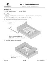
Grill Installation and Removal
Some fireplaces have grills above and below the glass frame. These grills may be installed
following the directions below (follow in reverse to remove).
Upper Grill Installation
Hold the grill at an angle and insert the lower
slot over the bushing on the fireplace (both
sides). You may need press on the grill to get
the tab over the bushing (this prevents the
grill from accidentally falling off).
Swing the grill upwards to engage the second
slot. You will need to lift the grill slightly to
get it over the bushing. Once in place the
grill is held in place by gravity.
Lower Grill Installation
Hold the grill at an angle and insert the lower
slot over the bushing on the fireplace (both
sides). You may need press on the grill to get
the tab over the bushing (this prevents the
grill from accidentally falling off).
Bend this the tab over on
both sides. This is the
end-stop for the lower grill,
it allows the grill to swing
forward.
Swing the grill upwards to engage
the second slot. You will need to lift
the grill slightly to get it over the
bushing. Once in place the grill is
held in place by gravity.

12 Maintenance
© Travis Industries 4071130 100-01196_000
Face Installation and Removal
Some fireplaces have a face that fits over the glass frame. The face can be removed following the
directions below.
Phillips
Screwdriver
Four screws hold the face
in place. The screws are
accessed through the
grills on the face.

Maintenance 13
© Travis Industries 4071130 100-01196_000
Glass Frame Removal and Installation
Warning: The appliance must be completely cool before removing the glass.
Warning: Do not strike or slam the glass.
Based upon the face being used, either:
(a) swing the access door down and remove the top grill,
(b) remove the face (unscrew or lift off - see the
instructions included with the face for details).
Open the four latches holding the glass frame in place
(start with the bottom three) - follow the directions shown
to the right.
a
Lift the glass frame up and
pull it forward to remove.
b
Re-Attaching the Glass Frame:
a) Hang the glass frame on the firebox.
b) While holding in place, attach the upper latches
(follow the instructions to the right in reverse).
c) Lift the glass frame slightly and attach the lower latches.
NOTE: Make sure the glass frame is all the way in place - it
should be flush with the front of the fireplace when installed.
NOTE:
You may need to lift
the glass frame
while re-attaching.
Glass
Top of
Firebox
Latch
Catch
(on glass frame)

14 Maintenance
© Travis Industries 4071130 100-01196_000
Glass Frame Removal and Installation (continued)
The latch can come loose from glass frame anchor. This occurs when it is turned 1/4 turn when it is
disengaged. Follow the directions below to re-install the latch if it becomes loose.
Top of
Firebox
Hold the latch at an angle and insert it into the slot on the glass frame anchor.
NOTE: this slot may be at a
different angle than illustrated.
Note how the washer on the latch fits behind the flange on the
glass frame anchor.
Glass Frame
Anchor
Once fully inserted, turn the latch until it is upright.
Latch

Maintenance 15
© Travis Industries 4071130 100-01196_000
Log Set Installation
Logs in Place – FRONT SIDE
NOTE: This fireplace has a front side and back side. The front side (pictured to the right) is the side
with the gas control valve.
Logs in Place – BACK SIDE

16 Maintenance
© Travis Industries 4071130 100-01196_000
Center Log Installation
The log shelf has two tabs
used to align the center log.
Bend these tabs as shown to
the right.
Place the center log in
place. Make sure the two
tabs on the log shelf insert
into the two holes on the
bottom of the log.
Bend these two tabs up 90°. They are used
as pins to locate the center log.
Once in place,
rotate the log
clockwise until
the indents in
the log contact
the grate.

Maintenance 17
© Travis Industries 4071130 100-01196_000
Front Left Log
Place the front left log as shown below. There is a ledge on the bottom of the log that aligns with
the edge of the center burner.
When in place, the front left log has a small gap to the center log.

18 Maintenance
© Travis Industries 4071130 100-01196_000
Front Left Upper Log
There are two pins on the front
left log. The pin to the right is
used to locate the front left
upper log.
The front left upper log has a groove and
one hole on the bottom. The groove fits
over the edge of the burner.
When in place, the front left upper log
looks like the picture to the right.

Maintenance 19
© Travis Industries 4071130 100-01196_000
Front Upper Center Log
The front upper center log
has two holes on its bottom
surface. One of the holes fits
over the pin on the center
log (see picture to the right).
The other fits over the pin on
the front left log.
When in place,
the front upper
center log looks
like the picture
to the right.

20 Maintenance
© Travis Industries 4071130 100-01196_000
Back Left Log
The back left log fits to the left of the
center log.
The groove on the bottom of the log fits
over the upper burner tray.
Make sure to slide the log towards the
center of the firebox. When in place, the
log will appear as shown in the picture to
the right.
/