Page is loading ...

STAINLESS STEEL
Dura–Flot 2400 Pumps
Severe–Duty rod and cylinder, for abrasive coatings.
Instructions–Parts List
308152Z1
Important Safety Instructions
Read all warnings and instructions in this manual.
Save these instructions.
See page 2 for Model Numbers, Maximum
Working Pressures and Table of Contents.
Part No. 222899 Shown
0566B

2 308152
List of Models
Pump Part No.
and Series Pump Model
Displacement
Pump Part No.
and SeriesK
Ratio
Maximum Fluid
Working Pressure
Maximum Air/Hydraulic
Input Pressure
222827,
Series A
Bulldogr 222803,
Series A
10:1 7.0 MPa, 69 bar
(1000 psi)
0.7 MPa, 7 bar
(100 psi)
222899,
Series A
Kingt 222803,
Series A
20:1 13.8 MPa, 138 bar
(2000 psi)
0.7 MPa, 7 bar
(100 psi)
222898,
Series B
Quiet Kingt 222803,
Series A
20:1 13.8 MPa, 138 bar
(2000 psi)
0.7 MPa, 7 bar
(100 psi)
222943,
Series B
Premiert 222803,
Series A
34:1 23.0 MPa, 234 bar
(3400 psi)
0.7 MPa, 7 bar
(100 psi)
222900,
Series B
Viscountr 222803,
Series A
1.33:1 14.0 MPa, 138 bar
(2000 psi)
10.0 MPa, 103 bar
(1500 psi)
249157,
Series A
Premier 249991,
Series A
34:1 23.0 MPa, 234 bar
(3400 psi)
0.7 MPa, 7 bar
(100 psi)
249158,
Series A
Premier 249991
Series A
34:1 23.0 MPa, 234 bar
(3400 psi)
0.7 MPa, 7 bar
(100 psi)
253843
Series A
Premier 249991
Series A
34:1 23.0 MPa, 234 bar
(3400 psi)
0.7 MPa, 7 bar
(100 psi)
K This manual also covers displacement pumps 236226, 222994, 236230, and 222993. See pages 34 and 35.
Table of Contents
Warnings 3. . . . . . . . . . . . . . . . . . . . . . . . . . . . . . . . . . . . . .
Installation 7. . . . . . . . . . . . . . . . . . . . . . . . . . . . . . . . . . . . .
Air-Powered Pumps 8. . . . . . . . . . . . . . . . . . . . . . . . .
Hydraulic-Powered Pumps 10. . . . . . . . . . . . . . . . . .
Operation/Maintenance 13. . . . . . . . . . . . . . . . . . . . . . . .
All Pumps 13. . . . . . . . . . . . . . . . . . . . . . . . . . . . . . . .
Air-Powered Pumps 14. . . . . . . . . . . . . . . . . . . . . . . .
Hydraulic-Powered Pumps 16. . . . . . . . . . . . . . . . . .
Troubleshooting Chart 18. . . . . . . . . . . . . . . . . . . . . . . . .
Service 19. . . . . . . . . . . . . . . . . . . . . . . . . . . . . . . . . . . . . .
Required Tools 19. . . . . . . . . . . . . . . . . . . . . . . . . . . .
Disconnecting the Displacement Pump 19. . . . . . .
Reconnecting the Displacement Pump 20. . . . . . . .
Displacement Pump Service 21. . . . . . . . . . . . . . . .
Parts Drawings and Parts Lists 26. . . . . . . . . . . . . . . . . .
Pump Assemblies 26. . . . . . . . . . . . . . . . . . . . . . . . . .
Displacement Pumps 30. . . . . . . . . . . . . . . . . . . . . . .
Technical Data 36. . . . . . . . . . . . . . . . . . . . . . . . . . . . . . . .
Dimensions 44. . . . . . . . . . . . . . . . . . . . . . . . . . . . . . . . . . .
Mounting Hole Layouts 45. . . . . . . . . . . . . . . . . . . . . . . . .
Graco Standard Warranty 46. . . . . . . . . . . . . . . . . . . . . .
Graco Information 46. . . . . . . . . . . . . . . . . . . . . . . . . . . . .

308152 3
Symbols
Warning Symbol
WARNING
This symbol alerts you to the possibility of serious
injury or death if you do not follow the instructions.
Caution Symbol
CAUTION
This symbol alerts you to the possibility of damage to
or destruction of equipment if you do not follow the
instructions.
WARNING
INSTRUCTIONS
EQUIPMENT MISUSE HAZARD
Equipment misuse can cause the equipment to rupture or malfunction and result in serious injury.
D This equipment is for professional use only.
D Read all instruction manuals, tags, and labels before operating the equipment.
D Use the equipment only for its intended purpose. If you are uncertain about usage, call your Graco
distributor.
D Do not alter or modify this equipment. Use only genuine Graco parts and accessories.
D Check equipment daily. Repair or replace worn or damaged parts immediately.
D Do not exceed the maximum working pressure of the lowest rated system component. Refer to the
Technical Data section on page 36 for the maximum working pressure of this equipment.
D Use fluids and solvents which are compatible with the equipment wetted parts. Refer to the Tech-
nical Data section of all equipment manuals. Read the fluid and solvent manufacturer’s warnings.
D Do not kink or overbend hoses or use hoses to pull equipment.
D Route hoses away from traffic areas, sharp edges, moving parts, and hot surfaces. Do not expose
Graco hoses to temperatures above 82_C (180_F) or below –40_C (–40_F).
D Wear hearing protection when operating this equipment.
D Do not lift pressurized equipment.
D Comply with all applicable local, state, and national fire, electrical, and safety regulations.

4 308152
WARNING
SKIN INJECTION HAZARD
Spray from the gun, hose leaks, or ruptured components can inject fluid into your body and cause
extremely serious injury, including the need for amputation. Fluid splashed in the eyes or on the skin
can also cause serious injury.
D Fluid injected into the skin might look like just a cut, but it is a serious injury. Get immediate surgi-
cal treatment.
D Do not point the gun at anyone or at any part of the body.
D Do not put your hand or fingers over the spray tip.
D Do not stop or deflect leaks with your hand, body, glove, or rag.
D Do not “blow back” fluid; this is not an air spray system.
D Always have the tip guard and the trigger guard on the gun when spraying.
D Check the gun diffuser operation weekly. Refer to the gun manual.
D Be sure the gun trigger safety operates before spraying.
D Lock the gun trigger safety when you stop spraying.
D Follow the Pressure Relief Procedure on page 13 whenever you: are instructed to relieve pres-
sure; stop spraying; clean, check, or service the equipment; and install or clean the spray tip.
D Tighten all fluid connections before operating the equipment.
D Check the hoses, tubes, and couplings daily. Replace worn, damaged, or loose parts immediately.
Permanently coupled hoses cannot be repaired; replace the entire hose.
D Use only Graco approved hoses. Do not remove any spring guard that is used to help protect the
hose from rupture caused by kinks or bends near the couplings.
MOVING PARTS HAZARD
Moving parts, such as the air motor piston, can pinch or amputate your fingers.
D Keep clear of all moving parts when starting or operating the pump.
D Before servicing the equipment, follow the Pressure Relief Procedure on page 13 to prevent the
equipment from starting unexpectedly.

308152 5
WARNING
FIRE AND EXPLOSION HAZARD
Improper grounding, poor ventilation, open flames, or sparks can cause a hazardous condition and
result in a fire or explosion and serious injury.
D Ground the equipment and the object being sprayed. Refer to Grounding on page 7.
D If there is any static sparking or you feel an electric shock while using this equipment, stop spray-
ing immediately. Do not use the equipment until you identify and correct the problem.
D Provide fresh air ventilation to avoid the buildup of flammable fumes from solvents or the fluid
being sprayed.
D Eliminate all ignition sources such as pilot lights, cigarettes, and plastic drop cloths (static arc
hazard). Do not plug or unplug power cords or turn lights on or off in the spray area.
D Keep the spray area free of debris, including solvent, rags, and gasoline.
D Electrically disconnect all equipment in the spray area.
D Extinguish all open flames or pilot lights in the spray area.
D Do not smoke in the spray area.
D Do not turn on or off any light switch in the spray area while operating or if fumes are present.
D Do not operate a gasoline engine in the spray area.
D Keep a fire extinguisher in the working area.
TOXIC FLUID HAZARD
Hazardous fluid or toxic fumes can cause serious injury or death if splashed in the eyes or on the skin,
inhaled, or swallowed.
D Know the specific hazards of the fluid you are using.
D Store hazardous fluid in an approved container. Dispose of hazardous fluid according to all local,
state, and national guidelines.
D Always wear protective eyewear, gloves, clothing, and respirator as recommended by the fluid and
solvent manufacturer.

6 308152
Notes

308152 7
Installation
(ALL PUMPS)
Grounding
WARNING
FIRE AND EXPLOSION HAZARD
Before operating the pump, ground the
system as explained below. Also read
the section FIRE AND EXPLOSION
HAZARD on page 5.
1. King Pumps: use a ground wire and clamp. See
Fig. 1. Remove the ground screw (Z) and insert
through eye of ring terminal at the end of ground
wire (Y). Fasten ground screw back onto pump
and tighten securely. Connect the other end of the
wire to a true earth ground. Order Part No. 222011
Ground Wire and Clamp.
All Other Pumps: use a ground wire and clamp.
See Fig. 2. Loosen the grounding lug locknut (W)
and washer (X). Insert one end of a 1.5 mm@ (12
ga) minimum ground wire (Y) into the slot in lug (Z)
and tighten the locknut securely. Connect the other
end of the wire to a true earth ground. Order Part
No. 237569 Ground Wire and Clamp.
Fig. 1
TI1052
Y
Z
Fig. 2
W
X
Y
Z
0864
2. Air, fluid, and hydraulic hoses: Use only electrically
conductive hoses with a maximum of 500 feet (150
m) combined hose length to ensure grounding
continuity. Check the electrical resistance of your
hoses at least once a week. If the total resistance
to ground exceeds 29 megohms, replace the hose
immediately.
NOTE: Use a meter that is capable of measuring
resistance at this level.
3. Air compressor or hydraulic power supply: follow
manufacturer’s recommendations.
4. Spray gun: ground through connection to a prop-
erly grounded fluid hose and pump.
5. Fluid supply container: follow your local code.
6. Object being sprayed: follow your local code.
7. Solvent pails used when flushing: follow your local
code. Use only metal pails, which are conductive,
placed on a grounded surface. Do not place the
pail on a nonconductive surface, such as paper or
cardboard, which interrupts the grounding continu-
ity.
8. To maintain grounding continuity when flushing or
relieving pressure, hold a metal part of the spray
gun firmly to the side of a grounded metal pail,
then trigger the gun.
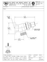
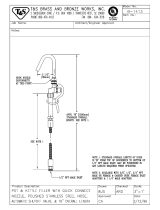
Optional Fluid Outlet Fitting
Part No. 184470 Fluid Outlet Fitting is available for
applications requiring a smaller fluid outlet fitting than
the standard 1–1/2 in. npt(m). The 184470 Fitting is
3/4 npt(m) x M42 x 2.0. Contact your Graco distributor
to order.

8 308152
Installation
(AIR-POWERED PUMPS)
NOTE: Reference numbers and letters in parentheses
in the text refer to the callouts in the figures and the
Parts Drawing.
NOTE: Always use Graco Parts and Accessories,
available from your Graco distributor. If you supply
your own accessories, be sure they are adequately
sized and pressure rated for your system.
Fig. 3 is only a guide for selecting and installing sys-
tem components and accessories. Contact your Graco
distributor for assistance in designing a system to suit
your particular needs.
Fig. 3
KEY
A Pump
B Wall Bracket
C Pump Runaway Valve
D Air Line Lubricator
E Bleed-Type Master Air Valve
(required, for pump)
F Pump Air Regulator
G Air Manifold
H Electrically Conductive Air Supply Hose
J Air Line Filter
K Bleed-Type Master Air Valve
(for accessories)
L Fluid Filter
M Fluid Drain Valve (required)
N Electrically Conductive Fluid Supply Hose
P Fluid Whip Hose
R Gun/Valve Swivel
S Airless Spray Gun
or Dispensing Valve
T Drum Suction Kit
Y Ground Wire (required; see page 7
for installation instructions)
A
B
C
D
E
F
G
H
JK
M
N
P
Y
MAIN AIR LINE
200 LITER (55 GAL.) DRUM
L
R
S
T
TYPICAL INSTALLATION
0626C

308152 9
Installation
(AIR-POWERED PUMPS)
System Accessories
WARNING
A bleed-type master air valve (E) and a fluid drain
valve (M) are required in your system. These
accessories help reduce the risk of serious injury,
including fluid injection and splashing of fluid in the
eyes or on the skin, and injury from moving parts if
you are adjusting or repairing the pump.
The bleed-type master air valve relieves air trapped
between this valve and the pump after the air is
shut off. Trapped air can cause the pump to cycle
unexpectedly. Locate the valve close to the pump.
The fluid drain valve assists in relieving fluid pres-
sure in the displacement pump, hose, and gun.
Triggering the gun to relieve pressure may not be
sufficient.
Air and Fluid Hoses
Be sure all air hoses (H) and fluid hoses (N and P) are
properly sized and pressure-rated for your system.
Use only electrically conductive hoses. Fluid hoses
must have spring guards on both ends. Use a whip
hose (P) and a swivel (R) between the main fluid hose
(N) and the gun/valve (S) for easier gun/valve move-
ment.
Mounting Accessories
WARNING
For Model 222943 Premier Pumps, do not lift the
pump by the lift ring when the total weight exceeds
550 lb (250 kg).
Mount the pump (A) to suit the type of installation
planned. Fig. 3 illustrates a wall-mounted system.
Pump dimensions and the mounting hole layout are
shown on pages 44 and 45.
If you are using an elevator or a cart, refer to the
separate manuals supplied with those components for
installation and operation instructions.
Air Line Accessories
Install the following accessories in the order shown in
Fig. 3, using adapters as necessary:
D An air line lubricator (D) provides automatic air
motor lubrication.
D A bleed-type master air valve (E) is required in
your system to relieve air trapped between it and
the air motor when the valve is closed (see the
WARNING at left). Be sure the bleed valve is easily
accessible from the pump, and is located down-
stream from the air regulator.
D An air regulator (F) controls pump speed and
outlet pressure by adjusting the air pressure to the
pump. Locate the regulator close to the pump, but
upstream from the bleed-type master air valve.
D A pump runaway valve (C) senses when the
pump is running too fast and automatically shuts off
the air to the motor. A pump which runs too fast can
be seriously damaged.
D An air manifold (G) has a swivel air inlet. It
mounts to a wall bracket, and provides ports for
connecting lines to air-powered accessories.
D An air line filter (J) removes harmful dirt and
moisture from the compressed air supply.
D A second bleed-type air valve (K) isolates the air
line accessories for servicing. Locate upstream
from all other air line accessories.
Fluid Line Accessories
Install the following accessories in the positions shown
in Fig. 3, using adapters as necessary:
D A fluid filter (L) with a 60 mesh (250 micron)
stainless steel element, to filter particles from the
fluid as it leaves the pump. It includes a fluid drain
valve (M), which is required in your system to
relieve fluid pressure in the hose and gun (see the
WARNING at left).
D A gun or valve (S) dispenses the fluid. The gun
shown in Fig. 3 is an airless spray gun for light to
medium viscosity fluids.
D A gun swivel (R) allows for easier gun movement.
D A suction kit (T) allows the pump to draw fluid
from a 200 liter (55 gallon) drum.

10 308152
Installation
(HYDRAULIC-POWERED PUMPS)
NOTE: Reference numbers and letters in parentheses
in the text refer to the callouts in the figures and the
parts drawing.
NOTE: Accessories are available from your Graco
distributor. If you supply your own accessories, be sure
they are adequately sized and pressure-rated to meet
the system’s requirements.
Fig. 4 is only a guide for selecting and installing sys-
tem components and accessories. Contact your Graco
distributor for assistance in designing a system to suit
your particular needs.
CAUTION
Keep the hydraulic supply system clean at all times.
Be sure that all hydraulic fluid lines are absolutely
clean. Blow out the lines with air and flush thoroughly
with solvent before connecting to the hydraulic
motor, to avoid introducing harmful contaminants into
the motor. Plug the hydraulic lines immediately when
they are disconnected.
Do not exceed 37.8 liter/min (10 gpm) hydraulic oil
volume to the motor, to avoid stalling the pump.
For optimum pump performance, keep the tempera-
ture of the hydraulic oil below 54_ C (130_ F).
Fig. 4
0627B
KEY
A Pump
B Wall Bracket
C Hydraulic Supply Line
D Hydraulic Return Line
E Drain Line (from pressure reducing valve)
F Pressure Gauge
G Flow Control Valve
H Pressure Reducing Valve
J Accumulator
K Drain Line (from motor drip pan)
L Fluid Filter
M Fluid Drain Valve (required)
N Electrically Conductive
Fluid Supply Hose
P Fluid Whip Hose
R Gun/Valve Swivel
S Airless Spray Gun or Dispensing Valve
T Drum Suction Kit
U Hydraulic Supply Line Shutoff Valve
V Hydraulic Return Line Shutoff Valve
Y Ground Wire (required, see page 7 for
installation instructions)
AA Hydraulic Return Line Filter
A
B
D
E
F
G
HJ
K
M
N
P
Y
200 LITER
(55 GAL.)
DRUM
L
R
S
T
U
C
V
HYDRAULIC
POWER SUPPLY
DRAINAGE
CONTAINER
AA
TYPICAL INSTALLATION

308152 11
Installation
(HYDRAULIC-POWERED PUMPS)
System Accessories
WARNING
A fluid drain valve (M) is required in your system to
help reduce the risk of serious injury, including fluid
injection and splashing of fluid in the eyes or on the
skin if you are adjusting or repairing the pump. The
fluid drain valve assists in relieving fluid pressure in
the displacement pump, hose, and gun. Triggering
the gun to relieve pressure may not be sufficient.
Mounting Accessories
Mount the pump (A) to suit the type of installation
planned. Fig. 4 illustrates a wall-mounted system.
Pump dimensions and the mounting hole layout are
shown on pages 44 and 45.
Filters
Be sure your hydraulic power supply is equipped with a
suction filter to the hydraulic pump and a system return
line filter (AA) of 10 micron size.
Carefully follow the manufacturer’s recommendations
on reservoir and filter cleaning, and periodic changes
of hydraulic fluid. Use only Graco-approved hydraulic
oil. Order Part No. 169236, 19 liter (5 gal.) or Part No.
207428, 3.8 liter (1 gal.). Do not substitute a lower
grade oil or one with a lower flash point.
Hydraulic Lines
The motor has a 3/4 npt(f) hydraulic oil supply fitting,
and a 1 in. npt(f) hydraulic oil return fitting. Use a
minimum 13 mm (1/2 in.) ID hydraulic supply line, and
a minimum 22 mm (7/8 in.) ID return line.
On the hydraulic supply line (C), install the following
accessories in the order shown in Fig. 4, using adapt-
ers as necessary:
D A shutoff valve (U) isolates the pump for service.
D A fluid pressure gauge (F) to monitor hydraulic oil
pressure to the motor and to avoid overpressurizing
the motor or displacement pump, and a pressure
and temperature compensated flow control
valve (G) to prevent the motor from running too
fast and possibly damaging itself.
D A pressure reducing valve (H), with a drain line
(E) run directly to the hydraulic return line (D).
D An accumulator (J) to reduce the hammering
effect caused by the motor reversing direction.
On the hydraulic return line (D), install the following
accessories in the order shown in Fig. 4, using adapt-
ers as necessary:
D A shutoff valve (V) isolates the pump for service.
D A filter (AA) of 10 micron size.
Hydraulic Motor Drip Pan
The hydraulic motor has a drip pan to collect any
leakage. Connect a 6 mm (1/4 in.) ID drain line (K) to
the barbed fitting on the drip pan, and place the free
end in a container to receive the drainage.
Fluid Supply Hoses
Be sure all fluid supply hoses (N and P) are properly
sized and pressure-rated for your system. Use only
electrically conductive hoses. Fluid hoses must have
spring guards on both ends. Use a whip hose (P) and
a swivel (R) between the main fluid hose (N) and the
gun/valve (S) to allow for easier gun/valve movement.
Fluid Line Accessories
Install the following accessories in the positions shown
in Fig. 4, using adapters as necessary:
D A fluid filter (L) with a 60 mesh (250 micron)
stainless steel element, to filter particles from the
fluid as it leaves the pump. It includes a fluid drain
valve (M), which is required in your system to
relieve fluid pressure in the hose and gun (see the
WARNING at left).
D A gun or valve (S) dispenses the fluid. The gun
shown in Fig. 4 is an airless spray gun for light to
medium viscosity fluids.
D A gun swivel (R) allows for easier gun movement.
D A suction kit (T) allows the pump to draw fluid
from a 200 liter (55 gallon) drum.

12 308152
Notes

308152 13
Operation/Maintenance
(All PUMPS)
Pressure Relief Procedure
WARNING
SKIN INJECTION HAZARD
The system pressure must be manually
relieved to prevent the system from
starting or spraying accidentally. Fluid
under high pressure can be injected through the
skin and cause serious injury. To reduce the risk of
an injury from injection, splashing fluid, or moving
parts, follow the Pressure Relief Procedure
whenever you:
D are instructed to relieve the pressure,
D stop spraying,
D check or service any of the system equipment,
D or install or clean the spray tips.
1. Lock the gun trigger safety.
2. Shut off the air or hydraulic supply to the pump.
3. In air-powered systems, close the bleed-type mas-
ter air valve (required in your system).
In hydraulic-powered systems, close the hydraulic
supply line valve first, then the return line valve.
4. Unlock the gun trigger safety.
5. Hold a metal part of the gun firmly to the side of a
grounded metal pail, and trigger the gun to relieve
pressure.
6. Lock the gun trigger safety.
7. Open the drain valve (required in your system),
having a container ready to catch the drainage.
8. Leave the drain valve open until you are ready to
spray again.
If you suspect that the spray tip or hose is completely
clogged, or that pressure has not been fully relieved
after following the steps above, very slowly loosen the
tip guard retaining nut or hose end coupling and relieve
pressure gradually, then loosen completely. Now clear
the tip or hose.
Packing Nut/Wet-Cup
Before starting, fill the packing nut (3) 1/3 full with
Graco Throat Seal Liquid (TSL) or compatible solvent.
See Fig. 5.
WARNING
To reduce the risk of serious injury whenever you
are instructed to relieve pressure, always follow the
Pressure Relief Procedure at left.
The packing nut is torqued at the factory and is ready
for operation. If it becomes loose and there is leaking
from the throat packings, relieve pressure, then
torque the nut to 128–156 NSm (95–115 ft-lb) using the
supplied wrench (104). Do this whenever necessary.
Do not overtighten the packing nut.
Fig. 5
Model 222899
Shown
1
Bleed hole must
face down
3
34, 35
104
1
0566B

14 308152
Operation/Maintenance
(AIR-POWERED PUMPS)
Flush the Pump Before First Use
The pump is tested with lightweight oil, which is left in
to protect the pump parts. If the fluid you are using
may be contaminated by the oil, flush it out with a
compatible solvent. See Flushing on page 15.
Starting and Adjusting the Pump
1. Refer to the Typical Installation on page 8.
Connect the suction kit (T) to the pump’s fluid inlet,
and place the tube into the fluid supply.
2. Be sure the air regulator (F) is closed. Then open
the pump’s bleed-type master air valve (E). Hold a
metal part of the spray gun/dispensing valve firmly
to the side of a grounded metal pail and hold the
trigger open. Now slowly open the air regulator
until the pump starts.
3. Cycle the pump slowly until all air is pushed out
and the pump and hoses are fully primed. Release
the gun/valve trigger and lock the trigger safety.
The pump should stall against pressure when the
trigger is released.
WARNING
SKIN INJECTION HAZARD
To reduce the risk of fluid injection, do not use your
hand or fingers to cover the bleed hole on the un-
derside of the bleeder valve body (34) when prim-
ing the pump. Use a crescent wrench to open and
close the bleeder plug (35). Keep your hands away
from the bleed hole.
4. If the pump fails to prime properly, open the bleed-
er valve plug (35) slightly. Use the bleed hole on
the underside of the valve body (34) as a priming
valve until the fluid appears at the hole. See Fig. 5.
Close the plug (35).
NOTE: When changing fluid containers with the hose
and gun already primed, open the bleeder valve plug
(35) to help prime the pump and vent air before it
enters the hose. Close the plug when all air is elimi-
nated.
CAUTION
Do not allow the pump to run dry. It will quickly
accelerate to a high speed, causing damage. If the
pump is running too fast, stop it immediately and
check the fluid supply. If the container is empty and
air has been pumped into the lines, refill the contain-
er and prime the pump and the lines, or flush and
leave it filled with a compatible solvent. Eliminate all
air from the fluid system.
5. With the pump and lines primed, and with ade-
quate air pressure and volume supplied, the pump
will start and stop as the gun/valve is opened and
closed. In a circulating system, the pump will
speed up or slow down on demand, until the air
supply is shut off.
6. Use the air regulator to control the pump speed
and the fluid pressure. Always use the lowest air
pressure necessary to get the desired results.
Higher pressures cause premature tip/nozzle and
pump wear.
WARNING
COMPONENT RUPTURE HAZARD
To reduce the risk of overpressurizing
your system, which could cause compo-
nent rupture and serious injury, never
exceed the specified Maximum Incoming Air Pres-
sure to the pump (see the Technical Data section
on pages 36–41).

308152 15
Operation/Maintenance
(AIR-POWERED PUMPS)
Shutdown and Care of the Pump
WARNING
To reduce the risk of serious injury whenever you
are instructed to relieve pressure, always follow the
Pressure Relief Procedure on page 13.
For overnight shutdown, stop the pump at the bottom
of its stroke to prevent fluid from drying on the ex-
posed displacement rod and damaging the throat
packings. Relieve the pressure.
Always flush the pump before the fluid dries on the
displacement rod. See Flushing below.
Flushing
WARNING
FIRE AND EXPLOSION HAZARD
Before flushing, read the section FIRE
AND EXPLOSION HAZARD on page
5. Be sure the entire system and flush-
ing pails are properly grounded. Refer to
Grounding on page 7.
Flush with a fluid that is compatible with the fluid you
are pumping and with the wetted parts in your system.
Check with your fluid manufacturer or supplier for rec-
ommended flushing fluids and flushing frequency. Al-
ways flush the pump before fluid dries on the displace-
ment rod.
WARNING
To reduce the risk of serious injury whenever you
are instructed to relieve pressure, always follow the
Pressure Relief Procedure on page 13.
1. Relieve the pressure.
2. Remove the spray tip from the gun.
3. Hold a metal part of the gun firmly to the side of a
grounded metal pail.
4. Start the pump. Always use the lowest possible
fluid pressure when flushing.
5. Trigger the gun.
6. Flush the system until clear solvent flows from the
gun.
7. Relieve the pressure.

16 308152
Operation/Maintenance
(HYDRAULIC-POWERED PUMPS)
Flush the Pump Before First Use
The pump is tested with lightweight oil, which is left in
to protect the pump parts. If the fluid you are using
may be contaminated by the oil, flush it out with a
compatible solvent. See Flushing on page 17.
Starting and Adjusting the Pump
1. Refer to the Typical Installation on page 10. Con-
nect the suction kit (T) to the pump’s fluid inlet,
and place the tube into the fluid supply.
2. Check the hydraulic fluid level before each use,
and add fluid as necessary.
3. Make certain that the supply line shutoff valve (U)
and the return line shutoff valve (V) are closed.
4. Start the hydraulic power supply.
5. Hold a metal part of the gun (S) firmly to the side
of a grounded metal pail and hold the trigger open.
6. Open the return line shutoff valve (V) first, then
slowly open the supply line shutoff valve (U).
7. Cycle the pump slowly until all air is pushed out
and the pump and hoses are fully primed.
8. Release the gun trigger and lock the trigger safety.
The pump should stall against pressure.
WARNING
SKIN INJECTION HAZARD
To reduce the risk of fluid injection, do not use your
hand or fingers to cover the bleed hole on the un-
derside of the bleeder valve body (34) when prim-
ing the pump. Use a crescent wrench to open and
close the bleeder plug (35). Keep your hands away
from the bleed hole.
9. If the pump fails to prime properly, open the bleed-
er valve plug (35) slightly. Use the bleed hole on
the underside of the valve body (34) as a priming
valve until the fluid appears at the hole. See Fig. 5.
Close the plug (35).
NOTE: When changing fluid containers with the hose
and gun already primed, open the bleeder valve plug
(35) to help prime the pump and vent air before it
enters the hose. Close the plug when all air is elimi-
nated.
CAUTION
Do not allow the pump to run dry. It will quickly
accelerate to a high speed, causing damage. If the
pump is running too fast, stop it immediately and
check the fluid supply. If the container is empty and
air has been pumped into the lines, refill the contain-
er and prime the pump and the lines, or flush and
leave it filled with a compatible solvent. Eliminate all
air from the fluid system.
10. With the pump and lines primed, and with ade-
quate hydraulic volume supplied, the pump will
start and stop as you open and close the gun. In a
circulating system, the pump will speed up or slow
down on demand, until the hydraulic power supply
is shut off.
11. Use the fluid pressure gauge (F) and flow control
valve (G) to control the pump speed and the fluid
outlet pressure. Always use the lowest hydraulic
flow and pressure necessary to get the desired
results. Higher pressures cause premature tip/noz-
zle and pump wear.
WARNING
COMPONENT RUPTURE HAZARD
To reduce the risk of overpressurizing
your system, which could cause compo-
nent rupture and serious injury, never
exceed 10.5 MPa, 105 bar (1500 psi) Maximum
Hydraulic Input Pressure to the pump, 14.0 MPa,
140 bar (2000 psi) Maximum Fluid Working Pres-
sure (see the Technical Data on pages 42–43).
To prevent overpressurizing the hydraulic motor or
its seals, always shut off the supply line valve (U)
first, then shut off the return line valve (V).
CAUTION
Do not allow the hydraulic oil temperature to exceed
54_C (130_F). The pump seals will wear faster and
leakage may occur if the pump is operated at higher
oil temperatures.

308152 17
Operation/Maintenance
(HYDRAULIC-POWERED PUMPS)
Shutdown and Care of the Pump
WARNING
To reduce the risk of serious injury whenever you
are instructed to relieve pressure, always follow the
Pressure Relief Procedure on page 13.
For overnight shutdown, stop the pump at the bottom
of its stroke to prevent fluid from drying on the ex-
posed displacement rod and damaging the throat
packings. Relieve the pressure.
Always flush the pump before the fluid dries on the
displacement rod. See Flushing below.
Flushing
WARNING
FIRE AND EXPLOSION HAZARD
Before flushing, read the section FIRE
AND EXPLOSION HAZARD on page
5. Be sure the entire system and flush-
ing pails are properly grounded. Refer to
Grounding on page 7.
Flush with a fluid that is compatible with the fluid you
are pumping and with the wetted parts in your system.
Check with your fluid manufacturer or supplier for rec-
ommended flushing fluids and flushing frequency. Al-
ways flush the pump before fluid dries on the displace-
ment rod.
WARNING
To reduce the risk of serious injury whenever you
are instructed to relieve pressure, always follow the
Pressure Relief Procedure on page 13.
1. Relieve the pressure.
2. Remove the spray tip from the gun.
3. Hold a metal part of the gun firmly to the side of a
grounded metal pail.
4. Start the pump. Always use the lowest possible
fluid pressure when flushing.
5. Trigger the gun.
6. Flush the system until clear solvent flows from the
gun.
7. Relieve the pressure.

18 308152
Troubleshooting Chart
WARNING
To reduce the risk of serious injury whenever you
are instructed to relieve pressure, always follow the
Pressure Relief Procedure on page 13.
1. Relieve the pressure.
2. Check all possible causes and problems before
disassembling the pump.
PROBLEM CAUSE SOLUTION
Pump fails to operate Restricted line or inadequate air/hy-
draulic supply; closed or clogged valves
Clear; increase air/hydraulic supply. Check that
valve are open.
Obstructed fluid hose or gun/valve; fluid
hose ID is too small
Open, clear*; use hose with larger ID.
Fluid dried on the displacement rod Clean; always stop pump at bottom of stroke;
keep wet-cup 1/3 filled with compatible solvent.
Dirty, worn, or damaged motor parts Clean or repair; see separate motor manual.
Pump operates, but
output low on both
tk
Restricted line or inadequate air/hy-
draulic supply, closed or clogged valves
Clear; increase air/hydraulic supply. Check that
valves are open.
p
strokes
Obstructed fluid hose or gun/valve; fluid
hose ID is too small
Open clear*; use hose with larger ID.
Bleeder valve open Close.
Fluid too heavy for pump priming Use bleeder valve (see pages 14 and 16); use
ram.
Worn packings in displacement pump Replace packings.
Pump operates, but
output low on down
Held open or worn intake valve Clear valve; service.
output low on down-
stroke
Fluid too heavy for pump priming Use bleeder valve (see pages 14 and 16); use
ram.
Pump operates, but
output low on upstroke
Held open or worn piston valve or pack-
ings
Clear valve; replace packings.
Erratic or accelerated
pump speed
Exhausted fluid supply Refill and prime.
pump speed
Fluid too heavy for pump priming Use bleeder valve (see pages 14 and 16); use
ram.
Held open or worn piston valve or pack-
ings
Clear valve; replace packings.
Held open or worn intake valve Clear valve; service.
* To determine if the fluid hose or gun is obstructed, follow the Pressure Relief Procedure on page 13. Disconnect
the fluid hose and place a container at the pump fluid outlet to catch any fluid. Turn on the air/hydraulic power just
enough to start the pump. If the pump starts when the air/hydraulic power is turned on, the obstruction is in the fluid
hose or gun.
NOTE: If you experience air motor icing, call your Graco Distributor.

308152 19
Service
Required Tools
D Set of socket wrenches
D Set of adjustable wrenches
D 24 in. adjustable wrench
D Torque wrench
D Rubber mallet
D Arbor press
D Soft wooden block (approx. 1 square ft in size)
D Large vise, with soft jaws
D Thread lubricant
D Anti-seize lubricant 222955
D LoctiteR 2760t or equivalent
NOTE: Service Tool 109508 is available as an acces-
sory. This tool fits over the top of the displacement rod,
making it easier to apply a 24 in. adjustable wrench or
3/4 in. drive socket when connecting or disconnecting
the rod from the piston assembly.
Disconnecting the Displacement Pump
1. Flush the pump, if possible. Stop the pump at the
bottom of its stroke.
WARNING
To reduce the risk of serious injury whenever you
are instructed to relieve pressure, always follow the
Pressure Relief Procedure on page 13.
2. Relieve the pressure.
3. Disconnect the air or hydraulic hose. Plug all
hydraulic hoses immediately, to prevent contami-
nation of the hydraulic system. Hold the fluid outlet
fitting (4) with a wrench to keep it from being
loosened while you disconnect the fluid hose.
WARNING
For Model 222943 Premier Pumps, do not lift the
pump by the lift ring when the total weight exceeds
550 lb (250 kg).
4. Disconnect the displacement pump (105) from the
motor (101) as follows. Be sure to note the relative
position of the pump’s fluid outlet to the air or
hydraulic inlet of the motor. If the motor does not
require servicing, leave it attached to its mounting.
CAUTION
Be sure to use at least two people when lifting, mov-
ing, or disconnecting the pump. This pump is too
heavy for one person. If you are disconnecting the
displacement pump from a motor which is still
mounted (for example, on a wall bracket), be sure to
support the displacement pump while it is being dis-
connected, to prevent it from falling and causing inju-
ry and property damage. Do this by securely bracing
the pump, or by having at least two people hold it
while another disconnects it.
If the pump is mounted on a cart, slowly tip the cart
backward until the handle rests on the ground, then
disconnect the displacement pump.
5. Using an adjustable wrench, unscrew the coupling
nut (103) from the connecting rod adapter (102).
Remove the coupling collars (108). Take care not
to lose or drop them. See Fig. 6.
6. Hold the tie rod flats with a wrench to keep the
rods from turning. Unscrew the nuts (106) from the
tie rods (107). Carefully remove the displacement
pump (105) from the motor (101).
7. Refer to page 22 for displacement pump service.
To service the air or hydraulic motor, refer to the
separate motor manual, supplied.

20 308152
Service
Reconnecting the Displacement Pump
WARNING
To reduce the risk of pinching or injuring hands or
fingers caught between the hydraulic motor drip
pan and the coupling nut, always use connecting
rod adapter 184595 and tie rods 184596 on model
222900 Viscount Pump. Never use connecting rod
adapter 184451 and tie rods 184452 on Model
222900; those parts do not allow sufficient clear-
ance between the drip pan and coupling nut.
NOTE: On Premier models, ensure that the rod adapt-
er (102) has not loosened during maintenance. Proper
torque is necessary to prevent the rod adapter from
loosening during the pump operation.
If the rod adapter (102) has loosened during mainte-
nance, remove the adapter and apply LoctiteR 2760t
(or equivalent) to the rod adapter and air motor piston
threads, and then torque as specified in Fig. 6.
1. Use at least two people to hold the displacement
pump while another reconnects it to the motor (see
the CAUTION at left). Orient the pump’s fluid
outlet to the air or hydraulic inlet as was noted in
step 4 under Disconnecting the Displacement
Pump. Position the displacement pump (105) on
the tie rods (107). See Fig. 6.
2. Screw the nuts (106) onto the tie rods (107) and
torque as noted in Fig. 6.
3. Place the coupling nut (103) on the displacement
rod (1), then place the coupling collars (108) into
the nut. Screw the coupling nut onto the connect-
ing rod adapter (102) loosely. Hold the connecting
rod adapter flats with a wrench to keep it from
turning. Use an adjustable wrench to tighten
coupling nut. Torque as noted in Fig. 6.
4. Torque the packing nut (3) to 128–156 NSm
(95–115 ft-lb).
5. Reconnect all hoses. Reconnect the ground wire if
it was disconnected. Fill the wet-cup (3) 1/3 full of
Graco Throat Seal Liquid or compatible solvent.
6. Turn on the air or hydraulic power supply. On
hydraulic pumps, open the hydraulic return line
valve first, then the supply line valve. Run the
pump slowly to ensure that it is operating properly.
/