Metroflush
®
Z6200 Series
Metroflush Piston-Operated
Flush Valve
Installation, Operation,
Maintenance and Parts Manual
Patented and Patents Pending
LIMITED WARRANTY
All goods sold hereunder are warranted to be free from defects in material and factory workmanship for a period of three years from the date of
purchase. Decorative finishes warranted for one year. We will replace at no cost goods that prove defective provided we are notified in writing
of such defect and the goods are returned to us prepaid at Sanford, NC, with evidence that they have been properly maintained and used in
accordance with instructions. We shall not be responsible for any labor charges or any loss, injury or damages whatsoever, including
incidental or consequential damages. The sole and exclusive remedy shall be limited to the replacement of the defective goods. Before
installation and use, the purchaser shall determine the suitability of the product for his intended use and the purchaser assumes all risk and
liability whatever in connection therewith. Where permitted by law, the implied warranty of merchantability is expressly excluded. If the products
sold hereunder are “consumer products,” the implied warranty of merchantability is limited to a period of three years and shall be limited solely
to the replacement of the defective goods. All weights stated in our catalogs and lists are approximate and are not guaranteed.
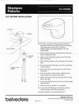
Metroflush
Piston-Operated Flush Valve
Z6200
Z6201
Z6203
Z6210
Z6203
Z6210
ADA
ADA

1 Install stop valve using proper supply escutcheon and sweat solder kit
if applicable.
3 Flushing of supply lines by using the following procedure is
recommended, after installation of all valves.
A. Close stop valves by using adjusting screw behind adjusting screw
cover. Do not remove stop valve cap.
B. Remove main valve body cover and working part from flush valve.
C. Replace only main valve body cover. Tighten main valve body cover.
D. Open the stop valve, by using the adjusting screw, until debris
is purged.
E. Shut the stop valve, replace working part and retighten cover.
2 Insert flush valve tailpiece into stop valve, being certain ‘O’-ring seal is
in place. Wet seal with water to lubricate. Hand tighten locknut.
Determine length of vacuum breaker tube required and cut as
necessary. Assemble vacuum breaker tube assembly between flush
valve and fixture spud.
4 Set flush valve for proper operation by adjusting stop valve. Stop valve
adjustments can only be made by using the adjusting screw located
behind the adjusting screw cover. (Water must be shut off at main
supply valve if stop cap is to be removed.) Final setting should provide
enough water flow to evacuate a closet fixture and should be such that
a urinal fixture will not overflow when continually flushed. Secure
adjusting screw cover.
O-Ring Seal

Metroflush
®
Parts Replacement & Repair Guide
Parts Identification
1. Handle Nut
2. Handle Sleeve
3. Handle Insert
4. Low Force/
ADA Compliant Handle
5. Actuator Rod
6. Handle O-Ring
7. Handle Spring
8. Handle Seal Retainer
9. Handle Seal
10. Gasket
11. Valve Body Cover
12. Valve Body Cover Gasket
13. Internal Kit
14. Main Seat
15. Valve Body
16. Vacuum Breaker Friction Washer
17. Vacuum Breaker Insert
18. Vacuum Breaker Duckbill
19. Vacuum Breaker Tube
20. Vacuum Breaker Tube Nut
21. Spud Nut
22. Spud Friction Washer
23. Spud Sleeve
24. Spud Escutcheon
25. Tailpiece
26. Snap Ring
27. Tailpiece O-Ring
28. Locking Nut
29. Vandal-Resistant Control Stop Cover
Covers and Repair Kits Product No.
Outside Cover - CP – Item 11 P6200-LL
Outside Cover O-Ring - Item 12 P6200-L12
Closet Repair Kit - Item 13 P6200-EC
Urinal Repair Kit - Item 13 P6200-EU
Low Consumption Closet Kit - Item 13 P6200-EC-WS1
Low Consumption Urinal Kit - Item 13 P6200-EU-WS1
Main Seat - Item 14 P6200-E14
Adjustable Tailpieces Product No.
Adjustable Tailpiece for Standard Flush Valve
Includes Items 25-27. P6000-J1
Tailpiece Coupling Assembly Includes Items 26-28 P6000-K
Tailpiece Locking Ring Includes Item 26 P6000-C30
Tailpiece O-Ring Includes Item 26 P6000-C31
Coupling Nut Includes Item 28 P6000-C32
Flush Connections and Spud Coupling Kits Product No.
Flush Tube Assembly for Flush Valves
Includes Items 16-20. P6000-A
Specify diameter and length: 1-1/2", 1-1/4", 3/4".
Vacuum Breaker Repair Kit Includes Items 16-18 P6000-B
Spud Coupling Assembly
Includes Items 21-24.
Specify size: 1-1/2", 1-1/4", 3/4". P6000-H
P6000-D
Stop Valve Repair Kit
P6000-C
XL Stop
Valve
Assembly
P6000-B
Vacuum
Breaker
Repair Kit
P6000-H
Spud
Coupling
Assembly
P6000-M
ADA Handle Assembly
P6000-MK
Handle Repair Kit
Handle Assembly and Repair Kits Product No.
ADA Handle Assembly (Side) Includes Items 2-10 P6000-M
Handle Repair Kit (Side) Includes Items 5-10 P6000-MK
Handle Seal Includes Item 9 P6000-M9
Handle Gasket Includes Item 10 P6000-M10
Control Stop Repair Kit and Parts Product No.
Control Stop Repair Kit for 1" and 3/4",
Includes Items 31-37 P6000-D-SD
Seal Seat for 1" and 3/4", Includes Item 37 P6000-D42
VP Control Stop Repair Kit for 1" and 3/4",
Includes Items 31-37. P6000-D-VP
Vandal-Resistant Cover Includes Item 29 P6000-VC
30. Stop Cap
31. Adjusting Screw
32. Guide Holder
33. Piston Guide
34. Guide O-Ring
35. Stop Spring
36. Piston
37. Piston Seal
38. Stop Body
39. Sweat Solder Adaptor
40. Supply Cover Tube
41. Cast Wall Escutcheon
Z6200 Series

ZURN PLUMBING PRODUCTS GROUP COMMERCIAL BRASS OPERATION
5900 ELWIN BUCHANAN DRIVE, SANFORD, NC, U.S.A. 27330 PHONE: 1-800-997-3876 FAX: 919/775-3541 WEBSITE: www.zurn.com
In Canada:
ZURN INDUSTRIES LIMITED 3544 NASHUA DRIVE, MISSISSAUGA, ONTARIO L4V 1L2 PHONE: 905/405-8272 FAX: 905/405-1292
© 2001 Zurn Industries, Inc. Printed in the U.S.A. Form No. FV1116, 8/01
MetroFlush
®
Service Instructions
Care of Chrome Plated Surfaces
The suggested cleaning of chrome plated surfaces is simply to clean them with mild soap and water, then dry. Commercial cleaning compounds
are never recommended.
Seasonal Use
Valves used in installations subject to shut down because of cold and freezing conditions should be maintained in the following manner. After the
main supply has been shut off and the water drained from the system, remove the stop valve cap and stop valve internals to allow the water to
drain from the flush valve itself.
PROBLEM CAUSE* CORRECTIVE ACTION
Valve will not operate. 1.) Stop valve is closed. 1.) Open stop valve.
2.) Supply valve is closed. 2.) Open supply valve.
Insufficient volume of water 1.) Stop valve is not open enough. 1.) Open stop valve for desired volume of water.
to adequately siphon fixture.
2.) Urinal piston installed in closet valve. 2.) Replace urinal piston with proper closet piston.
3.) Insufficient volume or pressure 3.) Consult fixture guide for minimum gallons per
at supply. minute flow and running pressure for satisfactory
fixture performance.
Flush valve shuts off too quick. 1.) Damaged piston. 1.) Install new P6200-EC, P6200-EU replacement
kit to remedy the problem.
2.) Enlarged by-pass orifice. 2.) Install new P6200-EC, P6200-EU replacement
kit to remedy the problem.
Valve is short flushing. 1.) Enlarged by-pass orifice. 1.) Install new P6200-EC, P6200-EU replacement
kit to remedy the problem.
2.) Urinal piston in closet flush valves. 2.) Install closet piston (Item #13).
Valve is flushing too long or 1.) Trip mechanism not seating properly 1.) Disassemble parts and rinse thoroughly.
not shutting off. due to foreign material between trip
mechanism and seat.
2.) By-pass orifice is plugged or partially 2.) Examine by-pass orifice and clean if necessary
plugged. being certain not to enlarge orifice opening.
3.) Line pressure is not adequate to force 3.) Pressure is inadequate or has dropped below
trip mechanism to seal. minimum operating range. Steps should be taken
to increase the line pressure.
Water splashes out of fixture. 1.) Supply volume is more than is 1.) Adjust downward on control stop.
necessary.
2.) Lime accumulation on vortex or 2.) Remove the lime build up.
spreader holes of fixture.
Flush is not considered quiet. 1.) Control stop may not be adjusted for 1.) Adjust the control stop for quiet operation
quiet operation. keeping in mind the fixture evacuation
requirements.
2.) Fixture may be contributing to noise. 2.) Check noise created by fixture by placing a cover
over the bowl opening to separate valve noise from
bowl noise. If it is determined the fixture is too
noisy consult with fixture manufacturer.
3.) Piping system may be source of noise. 3.) High pressure in the system can sometimes be
controlled by the stop valve. Other sources of noise
may be the absence of air chambers and shock
arrestors, loose pipes, improper size pipes, etc. In
these cases the building engineer should be consulted.
Handle assembly leaking. 1.) Handle assembly is not tight. 1.) Tighten handle assembly.
/