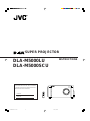
JVC DLA-M5000L User manual
- Category
- Data projectors
- Type
- User manual
This manual is also suitable for

DLA-M5000LU
DLA-M5000SCU
INSTRUCTIONS
SUPER PROJECTOR
For customer Use:
Enter below the Serial No. which is located
on the side panel of the cabinet. Retain this
information for future reference.
Model No.
Serial No.
M
E
N
U
/
E
N
T
E
R
QUICK
ALIGN.
AV HIDE
OPERATE
PRESET
AV
SHIFT ZOOM FOCUS
RM-M4100G REMOTE CONTROL UNIT
LENS
UT
+
DW
–
RGB/COMPUTER
LENS
LOCK UNLOCK
PAGE BACK
M5000LU/SCU Cover 01.3.5, 15:023

2
Thank you for purchasing this projector. Before using it, read and follow all instructions carefully to take full
advantage of the projector's capabilities.
SAFETY PRECAUTIONS
WARNING :
TO PREVENT FIRE OR SHOCK HAZARDS, DO NOT
EXPOSE THIS APPLIANCE TO RAIN OR MOISTURE.
CAUTION :
To reduce the risk of electric shock, do not remove cover.
Refer servicing to qualified service personnel.
FCC INFORMATION (U.S.A. only)
CAUTION: Changes or modification not approved by
JVC could void the user's authority to operate the
equipment.
NOTE: This equipment has been tested and found to
comply with the limits for a Class A digital device,
pursuant to Part 15 of the FCC Rules. These limits
are designed to provide reasonable protection against
harmful interference when the equipment is operated
in a commercial environment. This equipment
generates, uses, and can radiate radio frequency
energy and, if not installed and used in accordance
with the instruction manual, may cause harmful
interference to radio communications. Operation of
this equipment in a residential area is likely to cause
harmful interference in which case the user will be
required to correct the interference at his own
expense.
IMPORTANT SAFEGUARDS
Electrical energy can perform many useful functions. This
unit has been engineered and manufactured to assure
your personal safety. But IMPROPER USE CAN RESULT
IN POTENTIAL ELECTRICAL SHOCK OR FIRE
HAZARD. In order not to defeat the safeguards
incorporated into this product, observe the following basic
rules for its installation, use and service. Please read these
“Important Safeguards” carefully before use.
– All the safety and operating instructions should be read
before the product is operated.
– The safety and operating instructions should be retained
for future reference.
– All warnings on the product and in the operating
instructions should be adhered to.
– All operating instructions should be followed.
– Unplug this product from the wall outlet before cleaning.
Do not use liquid cleaners or aerosol cleaners. Use a
damp cloth for cleaning.
– Do not use attachments not recommended by the
product manufacturer as they may be hazardous.
– Do not use this product near water. Do not use
immediately after moving from a low temperature to high
temperature, as this causes condensation, which may
result in fire, electric shock, or other hazards.
– Do not place this product on an unstable cart, stand, or
table. The product may fall, causing serious injury to a
child or adult, and serious damage to the product. The
product should be mounted according to the
manufacturer’s instructions, and should use a mount
recommended by the manufacturer.
– When the product is used on a cart, care
should be taken to avoid quick stops,
excessive force, and uneven surfaces
which may cause the product and cart to
overturn, damaging equipment or causing
possible injury to the operator.
– Slots and openings in the cabinet are provided for
ventilation. These ensure reliable operation of the
product and protect it from overheating. These openings
must not be blocked or covered. (The openings should
never be blocked by placing the product on bed, sofa,
rug, or similar surface. It should not be placed in a built-
in installation such as a bookcase or rack unless proper
ventilation is provided and the manufacturer’s
instructions have been adhered to.)
For proper ventilation, separate the product from other
equipment, which may prevent ventilation and keep
distance more than 60 cm (19-3/4”).
IMPORTANT INFORMATION
This projector is equipped with a 3-blade grounding-type
plug to satisfy FCC rule. If you are unable to insert the
plug into the outlet, contact your electrician.
About burning-in of the D-ILA device
Do not allow the same still picture to be projected for a long
time or an abnormally bright video picture to be projected.
Do not project video images with high-intensity or high-
contrast on a screen. The video image could be burned in
to the D-ILA device.
Use special care when projecting video games or computer
program images. There is no problem with ordinary video-
cassette playback images.
M5000LU/SCU p.02-04 01.3.5, 15:032

3
– This product should be operated only with the type of
power source indicated on the label. If you are not sure
of the type of power supply to your home, consult your
product dealer or local power company.
– This product is equipped with a three-wire plug. This
plug will fit only into a grounded power outlet. If you are
unable to insert the plug into the outlet, contact your
electrician to install the proper outlet. Do not defeat the
safety purpose of the grounded plug.
– Power-supply cords should be routed so that they are
not likely to be walked on or pinched by items placed
upon or against them. Pay particular attention to cords
at doors, plugs, receptacles, and the point where they
exit from the product.
– For added protection of this product during a lightning
storm, or when it is left unattended and unused for long
periods of time, unplug it from the wall outlet and
disconnect the cable system. This will prevent damage
to the product due to lightning and power line surges.
– Do not overload wall outlets, extension cords, or
convenience receptacles on other equipment as this can
result in a risk of fire or electric shock.
– Never push objects of any kind into this product through
openings as they may touch dangerous voltage points
or short out parts that could result in a fire or electric
shock. Never spill liquid of any kind on the product.
– Do not attempt to service this product yourself as opening
or removing covers may expose you to dangerous
voltages and other hazards. Refer all service to qualified
service personnel.
– Unplug this product from the wall outlet and refer service
to qualified service personnel under the following
conditions:
a) When the power supply cord or plug is damaged.
b) If liquid has been spilled, or objects have fallen on
the product.
c) If the product has been exposed to rain or water.
d) If the product does not operate normally by following
the operating instructions. Adjust only those controls
that are covered by the Operation Manual, as an
improper adjustment of controls may result in damage
and will often require extensive work by a qualified
technician to restore the product to normal operation.
e) If the product has been dropped or damaged in any
way.
f ) When the product exhibits a distinct change in
performance – this indicates a need for service.
– When replacement parts are required, be sure the service
technician has used replacement parts specified by the
manufacturer or with same characteristics as the original
part. Unauthorized substitutions may result in fire, electric
shock, or other hazards.
– Upon completion of any service or repairs to this product,
ask the service technician to perform safety checks to
determine that the product is in proper operating
condition.
– The product should be placed more than one foot away
from heat sources such as radiators, heat registers,
stoves, and other products (including amplifiers) that
produce heat.
– When connecting other products such as VCR’s, and
personal computers, you should turn off the power of
this product for protection against electric shock.
– Do not place combustibles behind the cooling fan. For
example, cloth, paper, matches, aerosol cans or gas
lighters that present special hazards when over heated.
– Do not look into the projection lens while the illumination
lamp is turned on. Exposure of your eyes to the strong
light can result in impaired eyesight.
– Do not look into the inside of this unit through vents
(ventilation holes), etc. Do not look at the illumination
lamp directly by opening the cabinet while the illumination
lamp is turned on. The illumination lamp also contains
ultraviolet rays and the light is so powerful that your
eyesight can be impaired.
– Xenon gas is enclosed with high pressure inside the light-
source lamp (lamp unit) of this projector. If you drop or
impart a shock to the lamp, or discard it as is, there is
the possibility of explosion, leading to personal injury.
Use special care when handling the lamp. For any
unclear points, consult your product dealer.
– Use only the accessory cord designed for this product to
prevent shock.
The power supply voltage rating of this product is AC
220 V~ 240 V, the power cord attached conforms to
the following power supply voltage. Use only the
power cord designated by our dealer to ensure Safety
and EMC.
When it is used by other power supply voltage, power
cable must be changed.
Consult your product dealer.
SAFETY PRECAUTIONS (Cont.)
*DO NOT allow any unqualified person to
install the unit.
Be sure to ask your dealer to install the unit
(eg. attaching it to the ceiling) since special technical
knowledge and skills are required for installation.
If installation is performed by an unqualified person, it
may cause personal injury or electrical shock.
Power supply voltage: AC 220 V~ 240 V
M5000LU/SCU p.02-04 01.3.5, 15:033

4
Contents
SAFETY PRECAUTIONS ........................... 2
Accessories ............................................... 5
Controls and Features .............................. 6
Front Side / Top Surface / Right Side....................6
Left-hand side / Back Side ....................................7
Control Panel ........................................................8
Connector Panel .................................................10
Remote Control Unit ........................................... 11
MENU / ENTER (Menu Operation) Button..........13
Installing Batteries............................................... 13
Installing the Projector ........................... 14
Precautions for Installation.................................. 14
Lens Shift Function ............................................. 16
Projection Distances and Screen Sizes ..............18
Connecting to Various Devices.............. 19
Signals that Can Be Input to the Projector..........19
Examples of System Configuration.....................20
Connecting to Computer Devices ....................... 21
Connecting to Devices which Control the
Projector.........................................................22
Connecting the Power Cord (Supplied) ..............23
When Turning On the Devices Connected to the
Projector.........................................................24
Basic Operations..................................... 25
1. Turning on the Power....................................... 25
2. Select the video input to be projected .............26
3. Adjust the screen size .....................................26
4. Adjust focus.....................................................27
• For Operating Other Functions ......................... 27
Operating the Setting Menu ................... 30
Making Basic Settings.........................................30
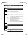
Operating the Main Menu ....................... 31
Configuration of the Main Menu..........................31
Operating the Main Menu (Basic Operation of the
Main Menu) ....................................................33
Changing the Color System ................................34
Changing the Language Display.........................35
Adjusting the Pixel Clock ....................................36
Adjusting the Screen Position .............................37
Adjusting Picture Quality.....................................38
Setting and Adjusting Other Functions
(OPTIONS) ....................................................41
Changing (Setting) the Source............................ 44
Setting Up Channels ...........................................47
Setting Up Channels (LINE setup)......................48
Setting Up Channels (SOURCE setup) ..............49
Setting Up Channels (SWNo. setup) ..................51
Changing Channels (CH Change) ...................... 52
Setting Up (or Changing) User Sources .............54
Setting Up (or Changing) the Display Size .........57
Filter Maintenance and Light-Source
Lamp Replacement ............................. 59
Cleaning and Replacing the Filter.......................59
About Light-Source Lamp Replacement .............60
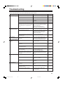
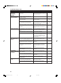
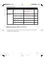
Troubleshooting ...................................... 61
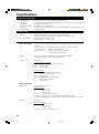
Specifications.......................................... 64
M5000LU/SCU p.02-04 01.3.5, 15:034

5
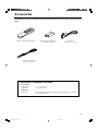
Remote control unit (RM-M4000G) AA/R6-size dry cell battery (×2)
(for checking operation)
Power code
[approx. 3.35 m (11 ft)]
Remote control cable
[approx. 15 m (49.2 ft)]
Accessories
The following accessories are included with this projector. Check for them; if any item is missing, please contact your
dealer.
Information on separately sold items
• Projection lens
GL-M4023SZ 3 : 1~7 : 1 zoom lens
GL-M4015S 1.5 : 1 fixed-focus lens
• Video board
PK-G1101D A board to be used for adding composite video signal input and Y/C (S-Video)
function to the projector.
M5000LU/SCU p.05-13 01.3.5, 15:045

6
Controls and Features
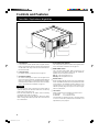
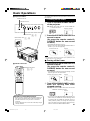
Front Side / Top Surface / Right Side
5
7
4
3
1
1
2
1
6
1
Adjustable foot
It is set at the shortest position when shipped from the
factory. Turn the foot to make the projector level. Adjustment
can be made in the range of ±4° from the vertical and ±5°
from the horizontal.
2
Connector panel
For details, refer to “Connector Panel” on page 10.
3
Air intake area (filter)
Air is taken in through this area to cool the light-source
lamp. If this area is blocked or if something that obstructs
taking in or exhausting air is placed around the projector,
heat may build up inside and could cause a fire. For details,
refer to “Precautions for Installation” on page 14.
CAUTIONS
• Be careful as paper, cloth or soft cushion could be drawn in
if placed nearby. Do not block the intake area, or heat may
build up and could cause a fire.
• Clean the filter periodically. For details, refer to “Cleaning
and Replacing the Filter” on page 59.
Deposition of dirt on the filter works to reduce the cooling
effect, causing heat to build up inside, which could cause a
fire or malfunction.
4
AC IN (power input) terminal
This is the power input terminal where the supplied power
cord is connected. For details, refer to page 23.
5
MAIN POWER switch
This is the main power switch. When it is turned on, the
projector goes into stand-by state, and the STAND BY
indicator on the control panel comes on.
ON [ ❙ ]: The main power turns on.
OFF [
‡‡
‡‡
‡]: The main power turns off.
6
Remote sensor
When operating with the remote control, aim it toward this
sensor. An additional remote sensor is provided on the back
of the projector. The effective operating distance of the
remote control is 10 m from each of the sensors. The
effective operating range of angles is 50° left and right,
and 15° up and down.
7
Lens mount
Attach a projection lens separately sold to this mount.
GL-M4023SZ 3 : 1~7 : 1 zoom lens
GL-M4015S 1.5 : 1 fixed-focus lens
For information on attaching the lens, consult the dealer
or service center who performed the installation and
adjustments of your projector.
M5000LU/SCU p.05-13 01.3.5, 15:046

7
Controls and Features (cont.)
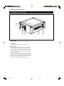
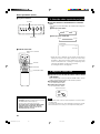
Left-hand side / Back Side
8
Exhaust vents
Vents for cooling fans through which warm air comes out.
9
Control panel
For details, refer to “Control Panel” (page 8 and 9).
p
Remote sensor
When operating with the remote control, aim it toward this
sensor. An additional remote sensor is provided on the front
of the projector. The effective operating distance of the
remote control is 10 m from each of the sensors. The
effective operating range of angles is 50° left and right,
and 15° up and down.
q
Exhaust vent (for the light-source lamp power supply)
Warm air comes out of this vent from the cooling fan for
the light-source lamp power supply. This fan continues
running as long as the MAIN POWER switch is on.
p
8
3
8
9
q
M5000LU/SCU p.05-13 01.3.5, 15:047

8
Controls and Features (cont.)
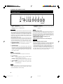
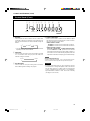
Control Panel
STAND BY
OPERATE
LAMP
EMERGENCY
AV RGB
SETTING
QUICK
ALIGN.
TEMP
1 23456789 p
1
STAND BY Indicator
ON :When in stand-by mode.
Blinking :When in cool-down mode.
CAUTIONS
• The cool-down mode continues for about 20 seconds, during
which projection cannot–be started again. After the cooling-
down period, the projector goes into stand-by mode, but the
cooling fans will continue to run for about 10 minutes more
before they stop (exept the cooling fan for the light-source
lamp power supply which continues running as long as the
MAIN POWER switch is on).
• The purpose of the cool-down mode is to prevent inner parts
from being deformed or broken by heat from the heated lamp
as well as to prolong the life of the lamp. Do not turn off the
main power switch while in the cool-down mode. Also, do
not block any of exhaust openings while in cool-down mode.
2
OPERATE indicator
ON: When the projector is in operation (projecting)
3
OPERATE button
When the projector is in the stand-by mode, press this
button for one or more seconds, and the main power switch
is turned on, causing the OPERATE indicator to light. Press
it again, and the projector goes into the cool-down mode,
then stand-by mode.
Memo
While in the cool-down mode:
If you press the OPERATE button, the projector is not tuned on.
4
Lamp indicator
ON : After the light-source lamp has been used for
more than approx. 900 hours.
Blinking : Replace the lamp. (Ask the dealer where you
purchased your projector to replace the lamp.)
5
TEMP indicator
ON :The temperature inside the projector has
abnormally risen.
Note
• While the TEMP indicator is on (during abnormal temperature), the
power is automatically cut off, and an emergency mode is shown
(with the EMERGENCY indicator blinking).
6
EMERGENCY indicator
Blinking: Something abnormal has occurred with the
projector.
Memo
About the emergency mode:
The emergency mode is shown when the following anomalies have
occurred with the projector (the EMERGENCY indicator blinks). In
the emergency mode, projection is automatically interrupted and the
cooling fans operate for about 10 minutes (except the cooling fan for
the light-source lamp power supply which continues running as long
as the MAIN POWER switch is on).
• When the light-source lamp has suddenly gone off.
• When the fans have stopped.
• When the temperature inside has risen abnormally high.
CAUTION
• When an emergency mode is shown:
After the cooling fans (except the one for the light-source
lamp power supply) have stopped, turn off the main power
switch and unplug the power cord from the wall outlet.
Check that the filter covers are correctly installed. Then, plug
in the power cord again and try operating the projector.
If it goes into an emergency mode again, after the cooling
fans have stopped, turn off the main power switch, unplug
the power cord, and call your dealer for repair.
M5000LU/SCU p.05-13 01.3.5, 15:048

9
Controls and Features (cont.)
Control Panel (Cont.)
7
AV button
Use this button to select a device such as a video deck
connected to the EXT. IN terminal of the projector. Each
time you press the button, the device selected changes as
follows:
Y/C
VIDEO
YPBPR
* Y/C and VIDEO can be used only when a video board
separately sold has been installed.
8
RGB button
Use this button to select a device connected to the RGB
-1 or -2 terminals. Each time you press the button, the
selection changes as follows:
RGB 1
RGB 2
9
SETTING button
Use this button to call up the setting menu. For details,
refer to “Making Basic Settings” on page 30.
p
QUICK ALIGN. button
While a menu screen is shown, use this button to adjust
the values for the item selected. When no menu is shown,
the quick alignment function works.
• When a menu is shown
button: The value for the selected item increases.
button: The value for the selected item decreases.
• When no menu is shown
Press the button and button at the same time:
QUICK-ALIGNMENT is displayed on the screen and the
quick alignment function works (TRACKING, PHASE, H.
POS. and V. POS. are automatically adjusted). When the
adjustment is finished, the display goes off automatically.
Memo
The quick alignment function :
• Works for computer input (RGB- 1 and - 2 input terminals) signals.
• Does not work for video input (EXT. IN input terminal) signals.
CAUTION
• Automatic adjustment with the quick alignment function
should be done on a bright still-picture screen. This function
may not work correctly on a dark screen or motion-picture
screen. If adjustment with this function is not satisfactory,
adjust TRACKING, PHASE, H. POS. and V. POS. manually
(see pages 30, 36 and 37).
STAND BY
OPERATE
LAMP
EMERGENCY
AV RGB
SETTING
QUICK
ALIGN.
TEMP
1 23456789 p
**
M5000LU/SCU p.05-13 01.3.5, 15:049

10
Controls and Features (cont.)
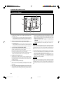
Connector Panel
1
Y/C (S video) input terminal (Mini DIN 4 pin)
Connect this terminal to the S video output terminal of a
video deck, etc.
* This terminal can be used if a video board (PK-G1101D)
sold separately has been installed. The terminal was not
provided when the projector was shipped from the factory.
2
VIDEO (composite video) input terminal (BNC)
Connect this terminal to the composite video output terminal
of a video deck, etc.
* This terminal can be used if a video board (PK-G1101D)
sold separately has been installed. The terminal was not
provided when the projector was shipped from the factory.
3
Y, PB/B-Y, PR/R-Y input terminals (BNC)
These are input terminals for component (Y, B-Y, R-Y)
signals or DTV-format (Y, P
B, PR) signals.
Device with component signal output terminals, such as
for NTSC and DTV-format, can be connected.
* For details about DTV-format signals (480i, 480p, 720p,
1080i) compatible with this unit, refer to page 66.
4
REMOTE terminal (mini jack)
This terminal is used to directly connect the remote con-
trol to the projector. Use the remote control cable supplied.
An infrared remote control extension unit can also be con-
nected to the jack.
5
RS-232C terminal (D-sub 9 pin)
This is a RS-232C interface-specified terminal. This
projector can be controlled by a computer connected
externally.
6
RGB OUT (RGB output) terminal (D-sub 3-row 15 pin)
The computer input signal projected on the screen is output.
A display unit can be used by connecting it to this terminal.
7
RGB IN (RGB input) -2 terminal (BNC)
These are input terminals for analog RGB signals, vertical
sync (V) signals, and horizontal sync (H) signals / composite
signals(Cs). Devices which have analog RGB signal output
terminals can be connected.
* Input of external sync signals is automatically
detected.
Detection of H/V signals or Cs signals causes automatic
switch to external sync. The priority order is H/V > Cs.
CAUTION
• When computer-related signals are input, the uppermost edge
of the screen may appear bowing if the sync signal input is
composite sync (Cs) or G on sync signal. In that case, use
separate sync signals for vertical sync (V) and horizontal sync
(H).
8
RGB IN (RGB input) -1 terminal (D-sub 3- row 15 pin)
This is an input terminal (PC) dedicated for computer
signals (RGB video signals and sync signals).
Connect the display output terminal of the computer to this
terminal. When a Macintosh or PC-9801/9802 series
computer is to be connected, use a suitable conversion
adapter separately available.
CAUTION
• When computer-related signals are input, the uppermost edge
of the screen may appear bowing if the sync signal input is
composite sync (Cs) or G on sync signal. In that case, use
separate sync signals for vertical sync (V) and horizontal sync
(H).
R
RGB
Y/C VIDEO
G H/CS
BV PR/R-Y
P
B/B-Y
Y
RGB OUT
RS-232C
REMOTE
RGB IN-2
CONTROL
EXT. IN
RGB IN-1
2
1
3
4
7
8
5
6
M5000LU/SCU p.05-13 01.3.5, 15:0410

11
Controls and Features (Cont.)
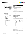
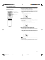
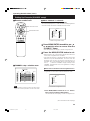
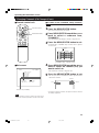
Remote Control Unit
M
E
N
U
/
E
N
T
E
R
QUICK
ALIGN.
AV HIDE
OPERATE
PRESET
AV
SHIFT ZOOM FOCUS
LENS
UT
+
DW
–
RGB/COMPUTER
LENS
LOCK UNLOCK
PAGE BACK
r
8
e
w
p
9
6
5
4
3
2
1
7
q
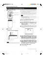
1
Remote control’s signal transmitter
2
OPERATE button
To turn on or off the power, press this button for one or
more seconds.
* About 30 seconds after the power has turned on, video
image will appear on the screen.
3
PAGE BACK button
While no menu is displayed, pressing this button causes a
direct channel to be displayed.
Memo
Direct channel display:
A direct channel display allows you to switch between chan-
nels which have lines and sources registered. For details,
refer to “Switching channels using a direct channel” (page
52).
4
MENU/ENTER button
Use this button to display the main menu, or while the main
menu is displayed, use the button to select an item to adjust
or make adjustment. While the main menu is displayed,
pressing MENU/ENTER displays a details setting
(submenu) if the selected item has a details setting.
For how to operate the buttons, see page 13.
5
RGB / COMPUTER button
Use this button to select the devices connected to the
projector’s RGB IN (RGB input) -1 and -2 input terminals.
Each time you press the button, the selection changes as
follows:
RGB 1
RGB 2
6
FOCUS (+/–) button
Use these buttons to adjust the focus of the projected
picture.
+: The focus point becomes more distant.
–: The focus point becomes nearer.
7
REMOTE terminal
Use a remote control cable to connect between the
projector and the remote control. For details, refer to
“Connecting to Devices which Control the Projector” on
page 22.
8
ZOOM (T/W) button
Use these buttons to increase or decrease the screen size.
(They can only be used when a zoom lens is used.)
T: The screen size decreases.
W: The screen size increases.
9
SHIFT (U/D) button
Use these buttons to adjust the height of the projection
screen when projectors are used in a stack configuration.
U: Moves the screen upwards.
D: Moves the screen downwards.
M5000LU/SCU p.05-13 01.3.5, 15:0411

12
Controls and Features (Cont.)
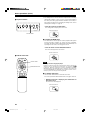
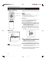
Remote Control Unit
M
E
N
U
/
E
N
T
E
R
QUICK
ALIGN.
AV HIDE
OPERATE
PRESET
AV
SHIFT ZOOM FOCUS
LENS
UT
+
DW
–
RGB/COMPUTER
LENS
LOCK UNLOCK
PAGE BACK
M
E
N
U
/
E
N
T
E
R
QUICK
ALIGN.
AV HIDE
OPERATE
PRESET
AV
SHIFT ZOOM FOCUS
LENS
UT
+
DW
–
RGB/COMPUTER
LENS
LOCK UNLOCK
PAGE BACK
VOLUME
–
+
r
8
e
w
p
9
6
5
4
3
2
1
t
q
7
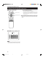
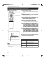
p
AV button
Use this button to select the devices such as a video
connected to the projector’s AV IN (EXT. input) terminal.
Each time you press the button, the selection changes as
follows:
Y/C
VIDEO
YPBPR
* Y/C and VIDEO can be used only when a video board
separately sold has been installed.
q
LENS LOCK Ô UNLOCK switch
With this switch set at the LOCK position, adjustment
operations (focus, zoom or shift) with the remote control
are disabled, preventing adjustment contents from being
inadvertently changed while the remote control is being
used. When adjustment is needed, set the switch to the
UNLOCK position.
w
PRESET button
While making adjustment on the main or setting menu,
use this button to reset the setting of the selected item to
the factory-set value. This button works only for numerical
settings and does not work for switching ON to OFF.
e
QUICK ALIGN. (Quick Alignment) button
Use this button to automatically adjust TRACKING,
PHASE, H. POS. and V. POS. of the projected video.
During the automatic adjustment, QUICK-ALIGNMENT
appears on the screen, and disappears after it is finished.
Memo
Quick alignment function:
Does not work for video input (EXT. IN input terminal) signals.
Works only for computer-related (RGB-1 and-2 input terminals)
signals.
CAUTION
• Automatic adjustment with the quick alignment function should be
done on a bright still-picture screen. This function may not work
correctly on a dark screen or motion-picture screen. If adjustment
with this function is not satisfactory, adjust TRACKING, PHASE, H.
POS. and V. POS. manually (see pages 30, 36 and 37).
r
AV HIDE button
Use this button to turn off the video image temporarily.
Pressing it again makes the video image to resume.
t
Not used with this projector
*
*
M5000LU/SCU p.05-13 01.3.5, 15:0412

13
Controls and Features (cont.)
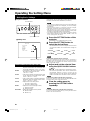
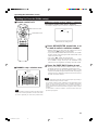
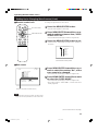
MENU / ENTER (Menu Operation) Button
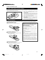
Install batteries in the remote control. If the remote control has started to work erratically, replace the batteries.
1
Open the back cover.
Open the back cover in the direction of the arrow.
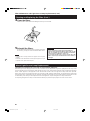
2
Install the batteries.
Place the two batteries (AA/R6-size) supplied in the remote
control as illustrated below.
Precautions for using batteries
If batteries are used incorrectly, they may crack or
leak liquid. This could cause a fire, burn, malfunction,
or staining or damaging the surrounding.
Beware of the following:
• Do not mix new and old batteries.
• Do not mix different types of batteries as they differ in
characteristics.
• Place batteries so they match the polarities indicated:
(+) to (+) and (–) to (–).
• Be sure to put the minus (–) end in first to avoid short-
circuiting.
• Use only designated batteries.
• Remove the batteries if not used for a prolonged period
of time.
• When the batteries are exhausted, replace them
immediately. Otherwise, liquid could leak, or malfunction
could occur due to leaked liquids. If the leaked liquid
contacts the skin, wipe it off with a cloth, otherwise the
skin could become rough.
• Do not put batteries into fire or try to recharge them.
• Batteries run for six months to one year in normal use.
But the batteries supplied are for confirming operation
and may not run that long. When the remote control starts
failing to work properly, replace the batteries with new
ones.
1
2
2
2
2
3
Close the back cover.
First fit the claw on the back cover into the case, then
close the back cover in the direction of the arrow.
The remote control supplied with this projector has only one button to navigate through the menus. Pressing the menu operation
button too strongly may cause an incorrect operation. So, before you use the button in an actual situation, have some practice
to make yourself familiar with using the button.
1 When using the MENU/ENTER button as a menu
operation button :
Press the button down straight when displaying the main
menu. While the main menu is displayed, if the selected
item has a details setting (submenu), pressing the button
will cause the submenu to be displayed.
2 When using the MENU/ENTER button as a cursor
moving button:
Press the button toward one of the 5/∞/2/3 marks.
While the main menu is displayed, use the button to select
an item to adjust or make adjustment.
ª
ª
·
·
Installing Batteries
M5000LU/SCU p.05-13 01.3.5, 15:0413

14
Installing the Projector
Precautions for Installation
■ When installing the projector, observe the followings:
• Do not use the projector placed on its side or upside down.
The projector can not be used by being placed on its side or upside down ;Otherwise, it could malfunction.
• Use the projector within the installed angle.
Avoid using the projector inclined ±5° or more right-to-left or left-to-right. This could cause color variation or harm the lamp
life.
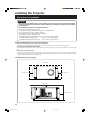
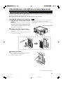
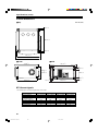
• Do not block the exhaust vents.
Do not use a cover which encloses the projector air-tight or blocks the exhaust vents. Allow sufficient space around the
projector. When the projector is enclosed in a space of the following dimensions, use an air conditioner so the temperature
inside becomes equal to the outside temperature.
Allowable minimum space required
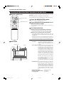
CAUTIONS
• Since the projector weighs approx. 70 kg (154 lbs.), be sure to use four or more people when lifting
or moving it; otherwise, the projector could possibly drop, causing personal injury and/or damage
to the projector.
• Do not install the projector in the following places :
• There is much water, humidity or dust.
• The projector may be subjected to oil smoke or cigarette smoke.
• On a soft surface such as a carpet or cushion.
• The projector may be subjected to direct sunlight.
• Temperature is high or humidity is low.
Allowable operation temperature range: + 5°C to + 40°C (41°F to 104°F)
Allowable relative humidity range: 90% or less (no condensation)
Allowable storage temperature range: –5°C to +60°C (23°F to 140°F)
305 mm (12”)
600 mm (23-
5
/8”) 600 mm (23-
5
/8”)
305 mm (12”)
600 mm (23-
5
/8”)
R
RGB
Y/C VIDEO
GH/CS
BV PR/R-Y
P
B/B-Y
Y
RGB OUT
RS-232C
REMOTE
RGB IN-2
CONTROL
EXT. IN
RGB IN-1
M5000LU/SCU p.14-24 01.3.5, 15:0514

15
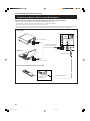
Precautions for Installation (Cont.)
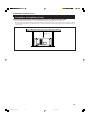
■ Observe the following points when installing the projector by hanging it from the ceiling
• To prevent falling or overturning, it is recommended that the projector be fixed to its stand with bolts.
• When mounting the projector to the ceiling, first install a special shelf and then set the projector on it securely. For safety
and maintenance purposes, a suitable facility is necessary to easily lift and lower the projector from the shelf for mainte-
nance access.
305 mm (12”)
or more
Installing the Projector (Cont.)
M5000LU/SCU p.14-24 01.3.5, 15:0515

16
Installing the Projector (Cont.)
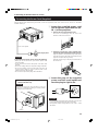
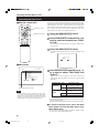
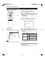
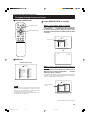
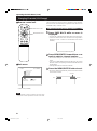
Lens Shift Function
Screen
Install the projector so the center of the projection
screen is the same height as the center of the lens.
Screen with 4 : 3 aspect ratio
■ Change of projection screen according
to aspect ratio
Screen with 16 : 9 aspect ratio
Center line of the lens
90° 90°
90°
CAUTIONS and NOTES
• When installing the screen, use a 4 : 3 aspect ratio picture.
(A 16 : 9 aspect ratio picture is projected based on the width of the range in which a 4 : 3 aspect ratio picture is projected.)
• The diagonal length of a 16 : 9 aspect ratio picture is about 91.8% that of a 4 : 3 aspect ratio picture. This value is a guide
and should be used as a reference.
• When projecting at the maximum projection distance, we recommend that the projector be used with the zoom on
the Tele (T).
• If sunlight or lamp light strikes the projection screen directly, the picture becomes whitish and dim. Be sure to use a
curtain, etc. to shield the light.
• Trapezoidal distortion may not be corrected.
Adjust the projector within the range of angle adjustment (up/down adjustment angle: +4°; horizontal adjustment angle:
±5°) so that it is set up level.
The separately sold lenses used on the projector have a lens shift function. With the lens used, you can adjust the projected
image vertically using the setting menu or the remote control’s SHIFT button U or D.
When using the projectors in a stack configuration (stacked one over another), make adjustment so that the picture of one
projector overlays exactly that of another using the lens shift function.
For detailed adjustment procedures, refer to “Operating the Setting Menu” (page 30) and “Controls and Features” (page 11).
For maximum amount of shift, refer to “Maximum Amount of Shift” (page 17).
(When the lens needs to be adjusted in horizontal angles, consult your dealer or service center.)
Note
• Some of the lenses (except GL-M4023SZ and GL-M4015S) to be introduced in the future may not feature the lens shift function.
Memo
Stack configuration:
Up to four projectors can be stacked and used together (stack configuration).
Using two or more projectors together, high image brightness can be attained. This allows you to project sufficiently bright image in a fairly large
auditorium or relatively bright place without using a heavy-duty projector.
CAUTION
To prevent damage to the projector during shipment, a shift center lock pin was used to fix the lens mechanism when the projector was shipped
out the factory. If you implement “SHIFT LENS” on the setting menu and the lens does not either move up or down, the shift center lock pin may
not have been removed. Consult your dealer or service center.
M5000LU/SCU p.14-24 01.3.5, 15:0516

17
Installing the Projector (Cont.)
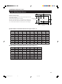
Lens Shift Function (Cont.)
Relational table for maximum shift amounts (aspect ratio 4 : 3)
Py(%) Px(%) Py(%) Px(%) Py(%) Px(%) Py(%) Px(%) Py(%) Px(%)
0.000 31.968 10.000 28.102 20.000 23.272 30.000 17.268 40.000 9.739
1.000 31.621 11.000 27.666 21.000 22.729 31.000 16.592 41.000 8.881
2.000 31.265 12.000 27.219 22.000 22.173 32.000 15.900 42.000 8.000
3.000 30.901 13.000 26.762 23.000 21.606 33.000 15.192 43.000 7.096
4.000 30.528 14.000 26.295 24.000 21.026 34.000 14.467 44.000 6.167
5.000 30.146 15.000 25.818 25.000 20.434 35.000 13.725 45.000 5.213
6.000 29.756 16.000 25.331 26.000 19.828 36.000 12.966 46.000 4.231
7.000 29.356 17.000 24.833 27.000 19.209 37.000 12.189 47.000 3.221
8.000 28.948 18.000 24.324 28.000 18.577 38.000 11.392 48.000 2.180
9.000 28.530 19.000 23.803 29.000 17.930 39.000 10.576 49.000 1.107
50.000 0.000
Py(%) Px(%) Py(%) Px(%) Py(%) Px(%) Py(%) Px(%)
0.000 31.968 10.000 26.609 20.000 19.421 30.000 9.747
1.000 31.503 11.000 25.980 21.000 18.581 31.000 8.599
2.000 31.234 12.000 25.333 22.000 17.716 32.000 7.410
3.000 31.528 13.000 24.666 23.000 16.824 33.000 6.178
4.000 30.018 14.000 23.980 24.000 15.905 34.000 4.900
5.000 29.491 15.000 23.274 25.000 14.958 35.000 3.573
6.000 28.949 16.000 22.548 26.000 13.981 36.000 2.193
7.000 28.389 17.000 21.800 27.000 12.973 37.000 0.756
8.000 27.813 18.000 21.030 28.000 11.933 37.509 0.001
9.000 27.220 19.000 20.237 29.000 10.858
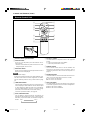
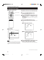
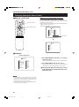
Maximum amount of shift
The maximum amount of vertical shift is restricted by the amount
of horizontal shift made.
The amount of shift is defined as follows:
With the screen width taken as 1, horizontal shift is defined as a
ratio (%) of the screen width, while with the screen height taken
as 1, vertical shift is defined as a ratio (%) of the screen height.
Horizontal screen sized
(x): 100%
Vertical screen size
(y): 100%
Screen after shifted
Screen with zero (0) shift
Py(%)
Px
(%)
Relational table for maximum shift amounts (aspect ratio 16 : 9)
M5000LU/SCU p.14-24 01.3.5, 15:0517

18
Installing the Projector (Cont.)
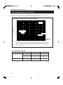
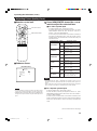
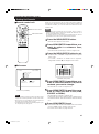
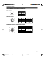
Projection Distances and Screen Sizes
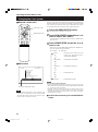
Lenses that can be used are a 3 : 1 ~ 7 : 1 zoom lens and a 1.5 : 1 fixed-focus lens. With a zoom lens used, you have a wider
latitude in selecting projection distance and installation space than with a fixed lens.
For how to install the lens, consult the dealer who installed and adjusted your projector or service center.
Relationship of screen size vs. projection distance
600
500
400
300
200
100
0510
15
20 25 30 35
40
45
Screen Size (inch)
Projection
Distance (m)
WIDE 3:1
TELE 7:1
Fixed-Focus Lens
1.5 : 1
Zoom Lens
In the shaded areas in the above graph, the projected image may be partially distorted or
missed out depending on the distance between the projector and the screen. To project an image
with no image distortion or missing, we recommend you to use the projector in the areas defined
with solid lines in the graph.
Lens Screen Size (Type) Projection Distance (m) Remarks
GL-M4023SZ zoom lens
80 – 300 5.06 – 18.65
3:1 wide
(80 – 600) (5.06 – 37.19)
60 – 200 8.65 – 28.56
7:1 tele
(60 – 300) (8.65 – 42.79)
GL-M4015S fixed-focus lens
69 – 208 2.09 – 6.50
––––––––
(65 – 250) (1.97 – 7.83)
Adjustable range of the lens
The numbers in ( ) represent the minimum to maximum adjustable range.
M5000LU/SCU p.14-24 01.3.5, 15:0518

19
Connecting to Various Devices
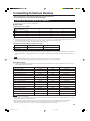
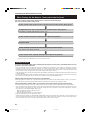
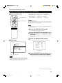
The following signals can be input to the projector:
■ Video signals
(1) Response to color systems
*
1
: Responds if Y/C output is available.
*
2
: Signifies that component signals (“Y, PB, PR ” / “ Y, B-Y, R-Y” / “G, B, R, H/CS, V”) conform to the signal timing (synchroniza-
tion and video period) of each color system. The color systems are used for convenience only.
*
3
: To use these terminals, a video board (separately sold) is required.
(2) Response to double density (*1), high-vision signals
Color system
NTSC 480i NTSC 4.43 PAL SECAM
Input terminal
VIDEO*
3
‡‡‡‡
Y/C*
3
‡‡*
1
‡ - - - - -
Y, P
B
/B-Y, P
R
/R-Y ‡*
2
‡*
2
‡*
2
‡*
2
G, B, R, H/C
S
, V ‡*
2
‡*
2
‡*
2
‡*
2
*
1
: Signals whose density of scanning lines/field is twice as high.
*
2
: Responds to signals whose horizontal scanning frequency is 31.5 kHz. NTSC can be made twice as dense by a line doubler
(separately available: recommended article). Also, possible to respond to fully-specified, decoded 525P progressive sig-
nals.
Note
• DTV-format signals (480i, 480p, 720p, 1080i) can be input into this unit (Y, P
B
/B-Y, P
R
/R-Y input terminals).
For details about DTV-format signals (480i, 480p, 720p, 1080i) compatible with this unit, refer to page 66.
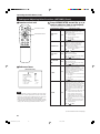
■ Computer signals
• Signals with the following resolutions can be input to the input terminal of RGB IN-1 (PC) or RGB IN-2 (G, B, R, H/Cs, V).
(The following signals are preset.)
Input terminal NTSC*
2
High-vision signal
Y, P
B
/B-Y, P
R
/R-Y ‡‡
G, B, R, H/C
S
, V ‡‡
Screen resolution (standard name) Horizontal frequency Vertical frequency Scanning method
640 × 400 (PC-9801) 24.8kHz 56.4Hz Non-interlace
640 × 350 (VGA1) 31.5kHz 70.1Hz Non-interlace
640 × 480 (VGA3) 31.5kHz 59.9Hz Non-interlace
640 × 480 (Macintosh 13”) 35.0kHz 66.7Hz Non-interlace
640 × 480 (VGA VESA) 37.5kHz 75.0Hz Non-interlace
800 × 600 (SVGA1) 37.9kHz 60.3Hz Non-interlace
800 × 600 (SVGA2) 48.1kHz 72.2Hz Non-interlace
832 × 624 (Macintosh16”) 49.7kHz 74.6Hz Non-interlace
1024 × 768 (XGA1) 48.4kHz 60.0Hz Non-interlace
1024 × 768 (XGA2) 56.5kHz 70.1Hz Non-interlace
1024 × 768 (Macintosh 19”) 60.2kHz 74.9Hz Non-interlace
1152 × 870 (Macintosh 21”) 68.7kHz 75.0Hz Non-interlace
1280 × 1024 (SXGA1) 64.0kHz 60.0Hz Non-interlace
1280 × 1024 (SXGA2) 70.8kHz 67.0Hz Non-interlace
1360 × 1024 (SXGA3: Mac Board) 80.0kHz 75.1Hz Non-interlace
Signals that Can Be Input to the Projector
* Before connection, be sure to turn off the projector and connected devices.
* Read the manual which comes with each device thoroughly.
Notes
• Interlace signals are not handled.
• Some signals other than listed above can be displayed. But they require adjustment. Even some of the signals listed above may require
adjustment depending on the video board used.
• When a signal other than listed above is input, the screen could be partially erased or an unneeded fold-over screen could appear.
• Even signals in the frequency range that can be input may not be displayed normally depending on the type of the signal.
• Composite sync.(Cs) and G on sync. signals can not handled depending on the devices connected.
M5000LU/SCU p.14-24 01.3.5, 15:0519

20
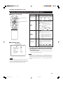
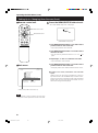
Connecting to Various Devices (Cont.)
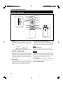
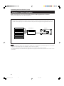
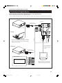
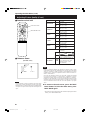
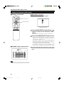
Examples of System Configuration
Before connection, be sure to turn off both the projector and the equipment to be connected.
• Also, read the manuals which came with the equipment.
R
RGB
Y/C VIDEO
GH/C
S
BV P
R
/R-Y
P
B
/B-Y
Y
RGB OUT
RS-232C
REMOTE
RGB IN-2
CONTROL
EXT. IN
RGB IN-1
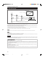
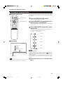
Example of a basic system
• By connecting an RGB switcher, a variety of input sources can be input to the projector as RGB signals. Using the
remote control supplied, you can select the channel for an input source and project an image optimal to the source.
HDTV 2
Computer 1
RGB switcher
Computer 2
Projector
HDTV 1
Note
Video image displayed on devices whose image signal is unstable, such as a video deck, may be disturbed. (This can occur when the
projectors is not yet adjusted at the time of installation, or when a new device is added.)
In such a case, ask the dealer where you purchased the projector or a local service center to adjust the projector.
It is recommended that you use a video deck that is equipped with an image signal correction function (such as time base corrector or frame
synchronizer).
M5000LU/SCU p.14-24 01.3.5, 15:0520
Page is loading ...
Page is loading ...
Page is loading ...
Page is loading ...
Page is loading ...
Page is loading ...
Page is loading ...
Page is loading ...
Page is loading ...
Page is loading ...
Page is loading ...
Page is loading ...
Page is loading ...
Page is loading ...
Page is loading ...
Page is loading ...
Page is loading ...
Page is loading ...
Page is loading ...
Page is loading ...
Page is loading ...
Page is loading ...
Page is loading ...
Page is loading ...
Page is loading ...
Page is loading ...
Page is loading ...
Page is loading ...
Page is loading ...
Page is loading ...
Page is loading ...
Page is loading ...
Page is loading ...
Page is loading ...
Page is loading ...
Page is loading ...
Page is loading ...
Page is loading ...
Page is loading ...
Page is loading ...
Page is loading ...
Page is loading ...
Page is loading ...
Page is loading ...
Page is loading ...
Page is loading ...
Page is loading ...
Page is loading ...
-
 1
1
-
 2
2
-
 3
3
-
 4
4
-
 5
5
-
 6
6
-
 7
7
-
 8
8
-
 9
9
-
 10
10
-
 11
11
-
 12
12
-
 13
13
-
 14
14
-
 15
15
-
 16
16
-
 17
17
-
 18
18
-
 19
19
-
 20
20
-
 21
21
-
 22
22
-
 23
23
-
 24
24
-
 25
25
-
 26
26
-
 27
27
-
 28
28
-
 29
29
-
 30
30
-
 31
31
-
 32
32
-
 33
33
-
 34
34
-
 35
35
-
 36
36
-
 37
37
-
 38
38
-
 39
39
-
 40
40
-
 41
41
-
 42
42
-
 43
43
-
 44
44
-
 45
45
-
 46
46
-
 47
47
-
 48
48
-
 49
49
-
 50
50
-
 51
51
-
 52
52
-
 53
53
-
 54
54
-
 55
55
-
 56
56
-
 57
57
-
 58
58
-
 59
59
-
 60
60
-
 61
61
-
 62
62
-
 63
63
-
 64
64
-
 65
65
-
 66
66
-
 67
67
-
 68
68


JVC DLA-M5000L User manual
- Category
- Data projectors
- Type
- User manual
- This manual is also suitable for
Ask a question and I''ll find the answer in the document
Finding information in a document is now easier with AI
Related papers
-
JVC DLA-M4000LU - D-ila Projector Instructions Manual
-
Meridian Projection Television DLA-HD2KE User manual
-
-
-
-
-
-
-
-
Other documents
-
Panasonic PT-D995U User manual
-
 Faroudja DILA1080pHD User manual
-
Meridian D-ILA 1080MF1 User manual
-
-
Sim2 SIM2 xTV INV User manual
-
Runco VX-3C Specification
-
Runco Home Theater System VX-6C User manual
-
Ask Proxima SX1 User manual
-
Mitsubishi XD3500U User manual
-
Mitsubishi DLP XD3200U User manual
