
Instructions for use.
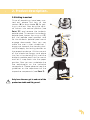
todd. the moveable standing trainer.
todd.

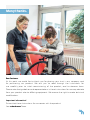
Many thanks.
Dear Customer
At this point we would like to thank you for placing your trust in our company and
for purchasing our product. We ask you to read through the Instructions for
use carefully prior to initial commissioning of the product, and to observe them.
Please note that guidelines and representations in these Instructions for use may deviate
from your product due to diering equipment. We reserve the right to make technical
modifications.
Important information!
Ensure that these Instructions for use remain with the product.
Your schuchmann Team

03
Contents.
1. Preparation. ................................................................................ 05
1.1 Transport ........................................................................................................................05
1.2 Safety measures prior to use ..............................................................................05
1.3 Safe disposal ...............................................................................................................05
1.3.1 Packaging ...........................................................................................................05
1.3.2 Product ................................................................................................................05
1.4 Where to store the Instructions for use ..........................................................05
2. Product description. .................................................................... 06
2.1 Material information ................................................................................................06
2.2 Handling and transport ........................................................................................06
2.3 Application areas, use according to the intended purpose .............07
2.4 Use not in accordance with the intended purpose / warning gui-
delines ............................................................................................................................08
2.5 Equipment for basic model ................................................................................. 08
2.5.1 Equipment acc. HMV (Medical Aids Register) ..................................08
2.6 List of accessories .................................................................................................... 09
2.7 Product overview ...................................................................................................... 09
2.8 General settings ........................................................................................................10
2.9 Getting in and out .....................................................................................................11
3. Settings ...................................................................................... 12
3.1 Angular adjustment of the central column ...................................................13
3.2 Height adjustment on the central column ................................................... 13
3.3 Rear wheels / drum brake .................................................................................... 14
3.4 Wheel camber ............................................................................................................ 15
3.5 Support rollers .............................................................................................................15
3.6 Foot plate .....................................................................................................................16
3.7 Divided foot plate ..................................................................................................... 16
3.8 Heel edges ................................................................................................................... 17
3.9 Footstraps ..................................................................................................................... 17
3.10 Knee pelotte pads .................................................................................................. 17
3.11 Combined spine and pelvic pelotte pad .....................................................18
3.12 Buttocks pelotte pad ............................................................................................. 19
3.13 Chest harness / chest pelotte pad with lateral guide ........................20
3.14 Backstrap ...................................................................................................................20
3.14 Back pelotte pad .................................................................................................... 21
3.16 Headrest ...................................................................................................................... 21
3.17 Therapy table ........................................................................................................... 22
4. Repairs and cleaning. .................................................................. 23
4.1 Cleaning ........................................................................................................................ 23
4.2 Repairs ........................................................................................................................... 23
4.3 Spare parts ................................................................................................................. 23
4.4 Duration of use and re-use ................................................................................ 23

5. Technical data. ............................................................................ 24
6. Guarantee. .................................................................................. 25
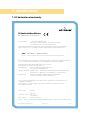
7. Identication. ............................................................................. 26
7.1 EC declaration of conformity ............................................................................... 26
7.2 Serial number / date of manufacture .............................................................27
7.3 Product version ...........................................................................................................27
7.4 Issue of the document ............................................................................................27
7.5 Name and address of the manufacturer, specialist dealer supplying
the product ...................................................................................................................27
04
Contents.

05
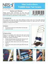
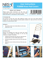
1. Preparation.
1.1 Transport
On receiving the product, please check it for completeness, lack of faults
and any transport damage.
Inspect the goods in the presence of your forwarder
Should transport damage have occurred, please cause an inventory (de-
termination of the faults) to be made in the presence of the forwarder.
Please send a complaint in writing to the specialist dealer responsible.
1.2 Safety measures prior to use
Correct usage of the standing trainer requires precise and careful training
of the accompanying person. We ask you to read through the Instructions
for use carefully prior to initial commissioning of the standing trainer, and
to observe them. Cushioned parts may become warm when exposed to
direct sunlight. Cover these parts or protect the equipment from direct
sunlight.
1.3 Safe disposal
In order to preserve and protect the environment, to prevent environmental
pollution and to improve the recycling of raw materials, please note the
disposal instructions in Points 1.3.1 and 1.3.2.
1.3.1 Packaging
The product packaging should be stored in case the product needs to
be transported again. Should you have to return the product for repairs
or in case of a guarantee claim, please if possible use the original box so
that the product is optimally packaged. Otherwise, separate the packa-
ging materials for recycling according to their classification. Do not leave
packaging materials unattended, as they are a possible source of danger.
1.3.2 Product
Separate the raw materials used in the product for recycling according to
their classification (see material information under Point 2.1).
1.4 Where to store the Instructions for use
Please store these Instructions for use carefully and ensure that these Ins-
tructions for use remain with the product in case of re-use.

06
2. Product description.
2.1 Material information
The base frame and the individual elements are made of steel or alumi-
nium which are non-corroding and powder-coated. All body supports
(except for the knee pelotte pads) are padded and covered. The covers
are made of 100% polyester or polyamide textile substrate, and are flame
resistant (according to DIN EN 1021-1+2).
2.2 Handling and transport
The standing trainer is not designed to be carried, as it is fitted with castors.
Should you have to carry the equipment due to obstacles, ensure that all
moving parts are tightened. Then two people should position themselves
next to the standing trainer, grip it on the left and right of the frame and
carry it to the required location. To transport the standing trainer, reduce
all adjustments to their most compact size (set lowest height etc.).

07
2. Product description.
2.3 Application areas, use according to the intended purpose
Indications
The standing trainer todd. is designed for indoor use and allows the user
to move around by means of drive wheels with handrims. It serves to train
standing in users who can hardly stand or who cannot stand, in particular
due to:
• Paraplegia
• Advanced multiple sclerosis
• Cerebral paresis
• Muscular dystrophy
Contraindications
In general, the indications for standing should be approved by a doctor or
orthopedist. It should therefore be clarified prior to procurement whether
contraindications exist for the patient. In general, any type of pain repre-
sents a contraindication. No standing trainer care should be conducted
without establishing prior to use whether the patient has an abnormal foot
position which requires medical attention.
Depending on the disease symptoms and therapy, please clarify how long
the user may stand in the standing trainer. The following symptoms may
occur in some cases:
• Circulation problems
• Pain in the leg and back areas
• Spastic seizures
It must also be clarified whether the user can be brought into full standing
position. For many users, only standing in a bent position is possible at first.
Never correct posture using force or strong pressure!

08
2. Product description.
2.4 Use not in accordance with the intended purpose / warning guide-
lines
• Ensure that the standing trainer is only used by one child/teenager.
• The standing trainer may only be used indoors on solid, even ground.
• Never leave the user unattended in the standing trainer.
• Correct usage of the standing trainer requires precise and careful
training of the accompanying person.
• The max. load (see Point 5) may not be exceeded.
• Do not use the standing trainer if it has defective, worn or missing parts.
• For reasons of fire safety, the standing trainer may not be placed close
to an open fire or any other strong source of heat such as electric or
gas heaters.
• Only use accessories and spare parts made by Schuchmann, otherwise
you will endanger the user.
• Only use the standing trainer if all components have been correctly
mounted and adjusted.
• When adjusting the standing trainer there is the risk of trapping or
crushing limbs.
• Users who have diculty reading must have someone read these Inst-
ructions for use aloud so that they understand how to use the standing
exercise trainer.
2.5 Equipment for basic model
• Base frame (standard) with height and depth-adjustable foot support
and four height-adjustable support rollers (75 mm), suspended with
locks at the back
• Base frame (abducting) with individually adjustable footrests, with two
height-adjustable support rollers (75 mm) at the front and one support
roller (30 mm) at the back
• Incl. chest harness, buttocks pelotte pad and three-dimensionally ad-
justable knee pelotte pads with patella recess
• Angular adjustment of the central column mechanical from 0° - 15
• incl. drum brakes, easy to operate via locking lever
• Adjustable wheel camber
2.5.1 Equipment acc. HMV (Medical Aids Register)
Acc. the HMV (Medical Aids Register), the standing trainer todd. requires the
provision of heel edges and footstraps.

09
2. Product description.
2.6 List of accessories
• Chest structure
• Chest pelotte pad with lateral
guide
• Backstrap
• Knee pelotte pads
• Back pelotte pad
• Pelvic guidance pelotte pad
with lateral guide
• Buttocks pelotte pad
• Pelvic positioner
• Combined spine and pelvic
pelotte pads
• Headrest
• Therapy table with edge
• Shelf basket
• Rear wheels
• Rear wheels with closed hand rims
• Spoke guard
• Foot support
• Individually-adjustable footrests
• Heel edges
• Footstraps
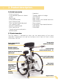
2.7 Product overview
The Fig. below is intended to show you the designation of the most
important components as well as the terms which you will find in these
Instructions for use.
Chest pelotte pad with
lateral guide
Combined spine and pelvic
pelotte pad
Knee pelotte pads
with adjustable
positioner
brackets
Therapy table
made from Plexiglas
Central column
can be inclined from 0° - 15°
Support rollers
Divided
foot plate
Buttocks harness /
buttocks pelotte pad
Rear wheels
with hand rims
Hand crank for adjustment
of the pelvic position
For extra safety:
Suspended
support wheels
with parking
brake

10
2. Product description.
2.8 General settings
todd. is completely assembled and delivered in the smallest possible
setting. Before the user is placed into the standing trainer, the necessary
presettings must be carried out.
User dimensions
Presettings
E
A
B
F
D
G
C
Taking the user's
dimensions
Carrying out adjustments to the standing trainer see
A
Body size Foot plate to headrest 3.2 + 3.16
B
Pelvic height
Adjust the foot plate up to the upper edge of
the buttocks pelotte pad support, then adjust
downwards by approx. 5 cm
3.6 + 3.12
C
Pelvic depth Depth of the buttocks pelotte pad 3.12
D
Pelvic width
Width of the combined spine and
Pelvic pelotte pad
3.11
E
Sternum height
Height of the chest pelotte pad with lateral
guide
3.13
F
Chest width
Width of the chest pelotte pad with lateral
guide
3.13
G
Knee height Height of knee pelotte pads 3.10

11
2. Product description.
2.9 Getting in and out
Once all presettings have been car-
ried out, please first lock all two
castors (A) or drum brake (B) for get-
ting in and out. Now bring the cent-
ral column into vertical position (see
Point 3.1) and remove the buttocks
pelotte pad. To remove the buttocks
pelotte pad, loosen the wing nut (C),
pull the pelotte pad upwards and
let the buttocks pelotte pad mount
engage downwards. Now you can
move the user in their wheelchair /
buggy etc towards the standing trai-
ner and apply the locking devices on
the respective device. Lift the user out
of the wheelchair/buggy and place
him/her in the standing unit, insert the
buttocks pelotte pad into the mount
and let it snap back into the upper
position. Now you can undertake the
fine adjustments on the individual
components. Please observe here the
guidelines on the adjustment of the
respective components (see Point 3).
Only have the user get in and out of the
product on stable and at ground.
A
B
C

3. Settings
12
Settings and adjustments to the product or accessories may only be made
by people who have been given the necessary instructions by a medical
product advisor. Please ensure that none of the user's extremities are in
the respective area when making adjustments of any kind to minimise the
risk of injury.

13
3. Settings
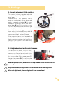
3.1 Angular adjustment of the central column
The central column can be adjusted
mechanically from 0 - 15° via a clam-
ping lever.
Please secure the standing trainer
against inadvertent rolling away and
apply the parking brake (A). In order
to adjust the angle, loosen the clam-
ping lever (B), bring the central column
into the required position and turn the
clamping lever to tighten again. For
the abducting version, the clamping
lever of the third roller (C) must also be
released before positioning the centre
column and then tightened again.
If the clamping lever is not located in a
position from which it is easy to opera-
te, its position can be changed when
idling by gently pulling the lever away
from the screw.
3.2 Height adjustment on the central column
The black inner profile, which is loca-
ted in the upper part on the central
column, can be pulled out and is thus
adjustable in height. In order to adjust
the inner profile in the upper area (D),
loosen the screws (E+F) and bring the
profile into the required position.
Hold the carriage tightly, otherwise it will slip into the central column under its
own weight.
Only undertake height adjustment if there is no-one in the standing trainer!
After each adjustment, please retighten all screw connections!
A
D
E
F
B
C

14
3. Settings
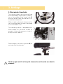
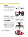
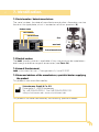
3.3 Rear wheels / drum brake
The drive wheels are puncture-free
and removable. Please press the but-
ton in the middle of the wheel hub (A)
and the drive wheel can be easily re-
moved and replaced.
When inserting the quick release axles,
you should be able to hear it engage
with an audible "click".
The standing trainer is equipped with
drum brakes on the drive wheels to
prevent it from rolling away unintenti-
onally and for stability.
Please apply the parking brake (B) to
activate the drum brake.
Check the tight axial t of the quick release axle each time the rear wheel is
mounted!
A
B

15
3. Settings
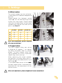
3.4 Wheel camber
The wheel camber can be individual-
ly adjusted and therefore adapted to
the user.
Please loosen the hexagon socket
screw (A), set the desired angle and
tighten the screw again. Please make
sure that the adjustment of the wheel
camber also changes the width of the
pelvis (see Point 5).
After each adjustment, please retighten
all screw connections!
3.5 Support rollers
The front support rollers are set at
a distance of approx. 1 cm above
the floor to prevent floor or carpet
edges. The rear support rollers are
spring-loaded to cushion a possible
impact (e.g. when rocking).
When adjusting the wheel camber,
the positions of these rollers are ch-
anged, but can be readjusted using a
Torx screw (B).
In the abducted version of the todd.
the rear support roller is automatically
adjusted with the adjustment of the
centre column.
After each adjustment, please retighten all screw connections!
A
for size 1 for size 2 for size 3+4
A
15° 12° 9°
B
12° 9° 6°
C
9° 6° 3°
D
- 3° 0°
A
B
C
D
B

1616
3. Settings
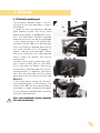
3.6 Foot plate
The foot plate is adjustable in height
and can be altered by loosening the
four screws (A) on the central column
(see Point 3.2). To adjust the depth,
loosen the star screw (B+C), which is
located under the foot plate. Now
bring the foot plate into the required
depth position.
3.7 Divided foot plate
The divided foot plate is height and
width adjustable with additional an-
gular adjustment for a pointed foot
setting. In order to adjust the height
of the divided foot plate, loosen the
screws (D+E) and bring the divided
footplate into the required position. In
order to adjust the divided foot pla-
te in width, loosen the screws (F+G)
on the underside and bring the divi-
ded footplate into the required po-
sition. In order to adjust the divided
foot plate in terms of the angle for
abduction of the legs, loosen the
screw (H) and turn the grub screw (I).
Further angle adjustment, e.g. for
pointed foot position, can be under-
taken via the Allen screw (J). Using a
ratchet joint, the entire divided foot
plate can be adjusted at an angle.
After each adjustment, please retighten
all screw connections!
F
G
I
J
H
D
D
E
E
CC
BB
A

17
3. Settings
3.8 Heel edges
The heel edges are mounted onto the
foot plate or the divided foot plate.
They can be adjusted in width, depth
and angle. In order to adjust the width
or the angle, loosen the wing screws (A)
below the foot plate and bring the
heel edges into the required position.
3.9 Footstraps
The footstraps can only be used in
connection with the heel edges. In or-
der to adjust the footstraps, loosen the
hook and eye fastener and bring the
footstrap into the required position.
3.10 Knee pelotte pads
The knee pelotte pads are adjustable
in height, angle and depth. The dis-
tance between the knee pelotte pads
can also be adjusted. In order to ad-
just the height, please hold the knee
pelotte pad tight, loosen the wing
screws (B) and bring the knee pelotte
pad support into the required position.
In order to adjust the depth, the ang-
le and the width, please loosen the
clamping lever (C) and bring the knee
pelotte pad into the required position.
After each adjustment, please retighten
all screw connections!
A
A
B
C

1818
3. Settings
3.11 Combined spine and pelvic pelotte pad
The combined spine and pelvic pe-
lotte pad is width, height and depth
adjustable.
The height can be adjusted by loo-
sening the screw (A). Now bring the
combined spine and pelvic pelotte
pad into the required position. In or-
der to adjust the width, please loosen
the screw (B) and bring the combined
spine and pelvic pelotte pad into the
required width position. In order to ad-
just the depth, pull the cover from the
pelotte pad and loosen the screws (C).
Now bring the combined spine and
pelvic pelotte pad into the required
depth position.
After each adjustment, please retighten
all screw connections!
C
A
B

19
3. Settings
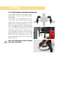
3.12 Buttocks pelotte pad
The buttocks pelotte pad is self-lo-
cking and can be adjusted in height
and depth.
In order to lock the buttocks pelotte
pad, please tighten the wing screw
below the support tube (A) after inser-
tion. The fold-down buttocks pelotte
pad mount must then be re-engaged
in the upper position. For depth ad-
justment, button (B) must be pressed
and the buttocks pelotte pad mount
must be moved until it engages (11
depth settings are possible). When
doing so, the mount must be pressed
down slightly to release the locking
mechanism.
To adjust the height, there are hexa-
gon socket screws (C) on the back,
which are easy to loosen. Now bring
the buttocks pelotte pad into the re-
quired position. In addition, the height
can also be adjusted via the height
adjustment on the central column (see
Point 3.2).
If the adjustment range of the but-
tocks pelotte pad is not sucient, the
hand crank (D) can be used to adjust
the depth in order to adjust the depth
of the buttocks pelotte pad including
the pelvis pelotte pad.
After each adjustment, please retighten
all screw connections!
C
A
B
D

20
3. Settings
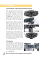
3.13 Chest harness / chest pelotte pad with lateral guide
Both the chest harness and the
chest pelotte pad with lateral gui-
de are adjustable in height, depth
and angle. In addition, the height
can also be adjusted via the height
adjustment on the central column
(see Point 3.2). In order to adjust the
height on the chest harness / chest
pelotte pad itself, please loosen the
four hexagon socket screws (A) and
bring the chest harness / chest pe-
lotte pad into the required position. To
adjust the angle of the chest harness /
chest pelotte pad, loosen the Allen
screws (B) and move the harness / pe-
lotte pad to the required position. To
adjust the depth of the chest harness /
chest pelotte pad, loosen the two Al-
len screws (C) and move the harness /
pelotte pad to the required position.
In order to adjust the width and the
angle of the lateral guide of the chest
pelotte pad with lateral guide, plea-
se remove the chest pelotte pad front
cover, loosen the four hexagon socket
screws (D) and bring the lateral guide
into the required position.
3.14 Backstrap
The backstrap is attached to the
chest pelotte pad with lateral guide.
The strap can be easily opened or
closed using a magnetic plug lock (E).
The strap can be adjusted in length
via the strap guide. Height and depth
adjustments can be undertaken via
the chest pelotte pad with lateral gui-
de (see Point 3.13).
After each adjustment, please retighten all screw connections!
B
E
C
AA
AA
D
D
D
D
Page is loading ...
Page is loading ...
Page is loading ...
Page is loading ...
Page is loading ...
Page is loading ...
Page is loading ...
Page is loading ...
-
 1
1
-
 2
2
-
 3
3
-
 4
4
-
 5
5
-
 6
6
-
 7
7
-
 8
8
-
 9
9
-
 10
10
-
 11
11
-
 12
12
-
 13
13
-
 14
14
-
 15
15
-
 16
16
-
 17
17
-
 18
18
-
 19
19
-
 20
20
-
 21
21
-
 22
22
-
 23
23
-
 24
24
-
 25
25
-
 26
26
-
 27
27
-
 28
28


Schuchmann todd Instructions For Use Manual
- Type
- Instructions For Use Manual
Ask a question and I''ll find the answer in the document
Finding information in a document is now easier with AI
Related papers
-
Schuchmann tim. Operating instructions
-
-
-
-
-
-
-
-
-
Other documents
-
 Featherlite ENZO User manual
-
Otto Bock Kimba Spring Instructions For Use Manual
-
 KARM Adjustable Knee Brace User guide
-
bort medical select Stabilo Instructions For Use Manual
-
 Coopers of Stortford K121 User manual
-
 NRS Healthcare P18808 Operating instructions
-
 NRS Healthcare P18808 Operating instructions
-
-
OasisSpace 9125A User manual
-
NordicTrack 831.21873.0 User manual


