aleo solar GmbH | Marius-Eriksen-Straße 1 | 17291 Prenzlau | Germany | info@aleo-solar.com
Quick Reference Manual Rel. 4.2, 08/2015, en-GB-DE (1)
Page 13/19
6 On lower frame part against sliding show.
Bolting
– horizontal/vertical –
Clamping
– Long module side, h/v –
Clamping
– Short module
side, h./v.–
Clamping
– Long and short
module side, h./v.–
Lay-in system
– Short side,
h./v. –
Lay-in system
– Long side, h./v. –
Load level I
(pressure, suction)
Upto2400Pa(approx.240kg/m²)
Option 1: Option 2: Assymetrical
clamping
Load level II
(pressure, suction)
Upto3900Pa(approx.390kg/m²)
10.8 Mounting drawings for modules with standard frames
10.8.1 Modules S18, S19, S79, S59
■ Load levels I and II
aleo solar GmbH
| Marius-Eriksen-Straße 1 | 17291 Prenzlau | Germany | [email protected]Quick Reference Manual Rel. 3.0, 07/2014, en-GB-DE (1) Page 13/19
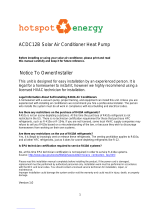
10.8 Mounting drawings for modules with standard frames
10.8.1 Modules S18, S19, S79
■ Load levels I and II
Fig.9 Mounting drawing for modules S18, S19, S79 at load levels I and II
Dimensions in mm. For a lay-in system, also refer to Ch. 10.5: „Insertion mounting“.
■ Load level III
Fig.10 Mounting drawing for module S18, S19, S79 at load level III
Dimensions in mm. For a lay-in system, also refer to Ch. 10.5: „Insertion mounting“.
Bolting Clamping Clamping Lay-in system Lay-in system
Option 1: Option 2: Asymmetrical
clamping
only for on-roof
or free-field installation
– Short module side, h. / v. –
– Short side, h. / v. – – Long side, h. / v. –
GID AS028f2-en-GB
200 200
– Long module side, horizontal / vertical –
– horizontal / vertical –
Mounting hole
990
430 800 430
1660
Mounting hole
430 800 430
430430
For 430 ≤ a ≤ 560 select:
b ≥ 300 and c ≥ 800
a and b can be exchanged.
abc
Load level I
(pressure, suction)
Up to 2400 Pa (approx. 240 kg/m²)
Load level II
(pressure, suction)
Up to 3900 Pa (approx. 390 kg/m²)
430430
200 200
only for on-roof
or free-field installation
Bolting Clamping Clamping Lay-in system Lay-in system
Option 1:
∆H < 45 mm
∆H ≥ 45 mm
– Short module side, h. / v. –
– Short side, h. / v. – – Long side, h. / v. –
GID AS029f2-en-GB
– Long module side, horizontal / vertical –
– horizontal / vertical –
Mounting hole
730
730
830830
200
Mounting hole
430430 800
200200 130130
For a < 200
For 330 ≤ a ≤ 430
430430
200
830830
a
a
Up to 5400 Pa (approx. 540 kg/m²)
Load level III (pressure, suction)
730
730 200
830830
Note: max. permitted
suction load 3900 Pa!
730730 200
830830
Max. suction load 3900 Pa!
430430
Option 2: Asymmetrical
clamping
200 200
200 200
Only for on-roof
or free-field installation
Only for on-roof
or free-field installation
Note: max. permitted
suction load 3900 Pa!
Max. suction load 3900 Pa!
aleo solar GmbH
| Marius-Eriksen-Straße 1 | 17291 Prenzlau | Germany | [email protected]Quick Reference Manual Rel. 3.0, 07/2014, en-GB-DE (1) Page 13/19
10.8 Mounting drawings for modules with standard frames
10.8.1 Modules S18, S19, S79
■ Load levels I and II
Fig.9 Mounting drawing for modules S18, S19, S79 at load levels I and II
Dimensions in mm. For a lay-in system, also refer to Ch. 10.5: „Insertion mounting“.
■ Load level III
Fig.10 Mounting drawing for module S18, S19, S79 at load level III
Dimensions in mm. For a lay-in system, also refer to Ch. 10.5: „Insertion mounting“.
Bolting Clamping Clamping Lay-in system Lay-in system
Option 1: Option 2: Asymmetrical
clamping
only for on-roof
or free-field installation
– Short module side, h. / v. –
– Short side, h. / v. – – Long side, h. / v. –
GID AS028f2-en-GB
200 200
– Long module side, horizontal / vertical –
– horizontal / vertical –
Mounting hole
990
430 800 430
1660
430430
For 430 ≤ a ≤ 560 select:
b ≥ 300 and c ≥ 800
a and b can be exchanged.
abc
Load level I
(pressure, suction)
Up to 2400 Pa (approx. 240 kg/m²)
Load level II
(pressure, suction)
Up to 3900 Pa (approx. 390 kg/m²)
430430
200 200
only for on-roof
or free-field installation
Bolting Clamping Clamping Lay-in system Lay-in system
Option 1:
∆H < 45 mm
∆H ≥ 45 mm
– Short module side, h. / v. –
– Short side, h. / v. – – Long side, h. / v. –
GID AS029f2-en-GB
– Long module side, horizontal / vertical –
– horizontal / vertical –
Mounting hole
730
730
830830
200
Mounting hole
430430 800
200200 130130
For a < 200
For 330 ≤ a ≤ 430
430430
200
830830
a
a
Up to 5400 Pa (approx. 540 kg/m²)
Load level III (pressure, suction)
730
730 200
830830
Note: max. permitted
suction load 3900 Pa!
730730 200
830830
Max. suction load 3900 Pa!
430430
Option 2: Asymmetrical
clamping
200 200
200 200
Only for on-roof
or free-field installation
Only for on-roof
or free-field installation
Note: max. permitted
suction load 3900 Pa!
Max. suction load 3900 Pa!
aleo solar GmbH
| Marius-Eriksen-Straße 1 | 17291 Prenzlau | Germany | [email protected]Quick Reference Manual Rel. 3.0, 07/2014, en-GB-DE (1) Page 13/19
10.8 Mounting drawings for modules with standard frames
10.8.1 Modules S18, S19, S79
■ Load levels I and II
Fig.9 Mounting drawing for modules S18, S19, S79 at load levels I and II
Dimensions in mm. For a lay-in system, also refer to Ch. 10.5: „Insertion mounting“.
■ Load level III
Fig.10 Mounting drawing for module S18, S19, S79 at load level III
Dimensions in mm. For a lay-in system, also refer to Ch. 10.5: „Insertion mounting“.
Bolting Clamping Clamping Lay-in system Lay-in system
Option 1: Option 2: Asymmetrical
clamping
only for on-roof
or free-field installation
– Short module side, h. / v. –
– Short side, h. / v. – – Long side, h. / v. –
GID AS028f2-en-GB
200 200
– Long module side, horizontal / vertical –
– horizontal / vertical –
Mounting hole
990
430 800 430
1660
Mounting hole
430 800 430
430430
For 430 ≤ a ≤ 560 select:
b ≥ 300 and c ≥ 800
a and b can be exchanged.
Load level I
(pressure, suction)
Up to 2400 Pa (approx. 240 kg/m²)
Load level II
(pressure, suction)
Up to 3900 Pa (approx. 390 kg/m²)
430430
200 200
only for on-roof
or free-field installation
Bolting Clamping Clamping Lay-in system Lay-in system
Option 1:
∆H < 45 mm
∆H ≥ 45 mm
– Short module side, h. / v. –
– Short side, h. / v. – – Long side, h. / v. –
GID AS029f2-en-GB
– Long module side, horizontal / vertical –
– horizontal / vertical –
Mounting hole
730
730
830830
200
Mounting hole
430430 800
200200 130130
For a < 200
For 330 ≤ a ≤ 430
430430
200
830830
a
a
Up to 5400 Pa (approx. 540 kg/m²)
Load level III (pressure, suction)
730
730 200
830830
Note: max. permitted
suction load 3900 Pa!
730730 200
830830
Max. suction load 3900 Pa!
430430
Option 2: Asymmetrical
clamping
200 200
200 200
Only for on-roof
or free-field installation
Only for on-roof
or free-field installation
Note: max. permitted
suction load 3900 Pa!
Max. suction load 3900 Pa!
aleo solar GmbH
| Marius-Eriksen-Straße 1 | 17291 Prenzlau | Germany | [email protected]Quick Reference Manual Rel. 3.0, 07/2014, en-GB-DE (1) Page 13/19
10.8 Mounting drawings for modules with standard frames
10.8.1 Modules S18, S19, S79
■ Load levels I and II
Fig.9 Mounting drawing for modules S18, S19, S79 at load levels I and II
Dimensions in mm. For a lay-in system, also refer to Ch. 10.5: „Insertion mounting“.
■ Load level III
Fig.10 Mounting drawing for module S18, S19, S79 at load level III
Dimensions in mm. For a lay-in system, also refer to Ch. 10.5: „Insertion mounting“.
Bolting Clamping Clamping Lay-in system Lay-in system
Option 1: Option 2: Asymmetrical
clamping
only for on-roof
or free-field installation
– Short module side, h. / v. –
– Short side, h. / v. – – Long side, h. / v. –
GID AS028f2-en-GB
– Long module side, horizontal / vertical –
– horizontal / vertical –
Mounting hole
990
430 800 430
1660
Mounting hole
430 800 430
430430
For 430 ≤ a ≤ 560 select:
b ≥ 300 and c ≥ 800
a and b can be exchanged.
abc
Load level I
(pressure, suction)
Up to 2400 Pa (approx. 240 kg/m²)
Load level II
(pressure, suction)
Up to 3900 Pa (approx. 390 kg/m²)
430430
200 200
only for on-roof
or free-field installation
Bolting Clamping Clamping Lay-in system Lay-in system
Option 1:
∆H < 45 mm
∆H ≥ 45 mm
– Short module side, h. / v. –
– Short side, h. / v. – – Long side, h. / v. –
GID AS029f2-en-GB
– Long module side, horizontal / vertical –
– horizontal / vertical –
Mounting hole
730
730
830830
200
Mounting hole
430430 800
200200 130130
For a < 200
For 330 ≤ a ≤ 430
430430
200
830830
a
a
Up to 5400 Pa (approx. 540 kg/m²)
Load level III (pressure, suction)
730
730 200
830830
Note: max. permitted
suction load 3900 Pa!
730730 200
830830
Max. suction load 3900 Pa!
430430
Option 2: Asymmetrical
clamping
200 200
200 200
Only for on-roof
or free-field installation
Only for on-roof
or free-field installation
Note: max. permitted
suction load 3900 Pa!
Max. suction load 3900 Pa!
aleo solar GmbH
| Marius-Eriksen-Straße 1 | 17291 Prenzlau | Germany | [email protected]Quick Reference Manual Rel. 3.0, 07/2014, en-GB-DE (1) Page 13/19
10.8 Mounting drawings for modules with standard frames
10.8.1 Modules S18, S19, S79
■ Load levels I and II
Fig.9 Mounting drawing for modules S18, S19, S79 at load levels I and II
Dimensions in mm. For a lay-in system, also refer to Ch. 10.5: „Insertion mounting“.
■ Load level III
Fig.10 Mounting drawing for module S18, S19, S79 at load level III
Dimensions in mm. For a lay-in system, also refer to Ch. 10.5: „Insertion mounting“.
Bolting Clamping Clamping Lay-in system Lay-in system
Option 1: Option 2: Asymmetrical
clamping
only for on-roof
or free-field installation
– Short module side, h. / v. –
– Short side, h. / v. – – Long side, h. / v. –
GID AS028f2-en-GB
200 200
– Long module side, horizontal / vertical –
– horizontal / vertical –
Mounting hole
990
430 800 430
1660
Mounting hole
430 800 430
430430
For 430 ≤ a ≤ 560 select:
b ≥ 300 and c ≥ 800
a and b can be exchanged.
abc
Load level I
(pressure, suction)
Up to 2400 Pa (approx. 240 kg/m²)
Load level II
(pressure, suction)
Up to 3900 Pa (approx. 390 kg/m²)
200 200
only for on-roof
or free-field installation
Bolting Clamping Clamping Lay-in system Lay-in system
Option 1:
∆H < 45 mm
∆H ≥ 45 mm
– Short module side, h. / v. –
– Short side, h. / v. – – Long side, h. / v. –
GID AS029f2-en-GB
– Long module side, horizontal / vertical –
– horizontal / vertical –
Mounting hole
730
730
830830
200
Mounting hole
430430 800
200200 130130
For a < 200
For 330 ≤ a ≤ 430
430430
200
830830
a
a
Up to 5400 Pa (approx. 540 kg/m²)
Load level III (pressure, suction)
730
730 200
830830
Note: max. permitted
suction load 3900 Pa!
730730 200
830830
Max. suction load 3900 Pa!
430430
Option 2: Asymmetrical
clamping
200 200
200 200
Only for on-roof
or free-field installation
Only for on-roof
or free-field installation
Note: max. permitted
suction load 3900 Pa!
Max. suction load 3900 Pa!
aleo solar GmbH
| Marius-Eriksen-Straße 1 | 17291 Prenzlau | Germany | [email protected]Quick Reference Manual Rel. 3.0, 07/2014, en-GB-DE (1) Page 13/19
10.8 Mounting drawings for modules with standard frames
10.8.1 Modules S18, S19, S79
■ Load levels I and II
Fig.9 Mounting drawing for modules S18, S19, S79 at load levels I and II
Dimensions in mm. For a lay-in system, also refer to Ch. 10.5: „Insertion mounting“.
■ Load level III
Fig.10 Mounting drawing for module S18, S19, S79 at load level III
Dimensions in mm. For a lay-in system, also refer to Ch. 10.5: „Insertion mounting“.
Bolting Clamping Clamping Lay-in system Lay-in system
Option 1: Option 2: Asymmetrical
clamping
only for on-roof
or free-field installation
– Short module side, h. / v. –
– Short side, h. / v. – – Long side, h. / v. –
GID AS028f2-en-GB
200 200
– Long module side, horizontal / vertical –
– horizontal / vertical –
Mounting hole
990
430 800 430
1660
Mounting hole
430 800 430
430430
For 430 ≤ a ≤ 560 select:
b ≥ 300 and c ≥ 800
a and b can be exchanged.
abc
Load level I
(pressure, suction)
Up to 2400 Pa (approx. 240 kg/m²)
Load level II
(pressure, suction)
Up to 3900 Pa (approx. 390 kg/m²)
430430
only for on-roof
or free-field installation
Bolting Clamping Clamping Lay-in system Lay-in system
Option 1:
∆H < 45 mm
∆H ≥ 45 mm
– Short module side, h. / v. –
– Short side, h. / v. – – Long side, h. / v. –
GID AS029f2-en-GB
– Long module side, horizontal / vertical –
– horizontal / vertical –
Mounting hole
730
730
830830
200
Mounting hole
430430 800
200200 130130
For a < 200
For 330 ≤ a ≤ 430
430430
200
830830
a
a
Up to 5400 Pa (approx. 540 kg/m²)
Load level III (pressure, suction)
730
730 200
830830
Note: max. permitted
suction load 3900 Pa!
730730 200
830830
Max. suction load 3900 Pa!
430430
Option 2: Asymmetrical
clamping
200 200
200 200
Only for on-roof
or free-field installation
Only for on-roof
or free-field installation
Note: max. permitted
suction load 3900 Pa!
Max. suction load 3900 Pa!
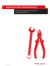
Fig.9 Mounting drawing for modules S18, S19, S79 at load levels I and II
Dimensions in mm. For a lay-in system, also refer to Ch. 10.5: „Insertion mounting“.
■ Load level III
Fig.10 Mounting drawing for module S18, S19, S79 at load level III
Dimensions in mm. For a lay-in system, also refer to Ch. 10.5: „Insertion mounting“.
min. 1 brace⁶ min. 1 brace⁶
Bolting
– horizontal/vertical –
Clamping
– Long module side, h/v –
Clamping
– Short module side,
h./v. –
Clamping
– Long and short
module side, h./v.–
Lay-in system
– Short side,
h./v. –
Lay-in system
– Long side, h./v. –
Load level III (pressure, suction)
Upto5400Pa(approx.540kg/m²)
ΔH < 45 mm
Option 1: Option 2:
Assymetrical clamping
Δ H > 45 mm
aleo solar GmbH
| Marius-Eriksen-Straße 1 | 17291 Prenzlau | Germany | [email protected]Quick Reference Manual Rel. 3.0, 07/2014, en-GB-DE (1) Page 13/19
10.8 Mounting drawings for modules with standard frames
10.8.1 Modules S18, S19, S79
■ Load levels I and II
Fig.9 Mounting drawing for modules S18, S19, S79 at load levels I and II
Dimensions in mm. For a lay-in system, also refer to Ch. 10.5: „Insertion mounting“.
■ Load level III
Fig.10 Mounting drawing for module S18, S19, S79 at load level III
Dimensions in mm. For a lay-in system, also refer to Ch. 10.5: „Insertion mounting“.
Bolting Clamping Clamping Lay-in system Lay-in system
Option 1: Option 2: Asymmetrical
clamping
only for on-roof
or free-field installation
– Short module side, h. / v. –
– Short side, h. / v. – – Long side, h. / v. –
GID AS028f2-en-GB
200 200
– Long module side, horizontal / vertical –
– horizontal / vertical –
Mounting hole
990
430 800 430
1660
Mounting hole
430 800 430
430430
For 430 ≤ a ≤ 560 select:
b ≥ 300 and c ≥ 800
a and b can be exchanged.
abc
Load level I
(pressure, suction)
Up to 2400 Pa (approx. 240 kg/m²)
Load level II
(pressure, suction)
Up to 3900 Pa (approx. 390 kg/m²)
430430
200 200
only for on-roof
or free-field installation
Bolting Clamping Clamping Lay-in system Lay-in system
Option 1:
∆H < 45 mm
∆H ≥ 45 mm
– Short module side, h. / v. –
– Short side, h. / v. – – Long side, h. / v. –
GID AS029f2-en-GB
– Long module side, horizontal / vertical –
– horizontal / vertical –
Mounting hole
730
730
830830
200
Mounting hole
430430 800
200200 130130
For a < 200
For 330 ≤ a ≤ 430
430430
200
830830
a
a
Up to 5400 Pa (approx. 540 kg/m²)
Load level III (pressure, suction)
730
730 200
830830
Note: max. permitted
suction load 3900 Pa!
730730 200
830830
Max. suction load 3900 Pa!
430430
Option 2: Asymmetrical
clamping
200 200
200 200
Only for on-roof
or free-field installation
Only for on-roof
or free-field installation
Note: max. permitted
suction load 3900 Pa!
Max. suction load 3900 Pa!
aleo solar GmbH
| Marius-Eriksen-Straße 1 | 17291 Prenzlau | Germany | [email protected]Quick Reference Manual Rel. 3.0, 07/2014, en-GB-DE (1) Page 13/19
10.8 Mounting drawings for modules with standard frames
10.8.1 Modules S18, S19, S79
■ Load levels I and II
Fig.9 Mounting drawing for modules S18, S19, S79 at load levels I and II
Dimensions in mm. For a lay-in system, also refer to Ch. 10.5: „Insertion mounting“.
■ Load level III
Fig.10 Mounting drawing for module S18, S19, S79 at load level III
Dimensions in mm. For a lay-in system, also refer to Ch. 10.5: „Insertion mounting“.
Bolting Clamping Clamping Lay-in system Lay-in system
Option 1: Option 2: Asymmetrical
clamping
only for on-roof
or free-field installation
– Short module side, h. / v. –
– Short side, h. / v. – – Long side, h. / v. –
GID AS028f2-en-GB
200 200
– Long module side, horizontal / vertical –
– horizontal / vertical –
Mounting hole
990
430 800 430
1660
Mounting hole
430 800 430
430430
For 430 ≤ a ≤ 560 select:
b ≥ 300 and c ≥ 800
a and b can be exchanged.
abc
Load level I
(pressure, suction)
Up to 2400 Pa (approx. 240 kg/m²)
Load level II
(pressure, suction)
Up to 3900 Pa (approx. 390 kg/m²)
430430
200 200
only for on-roof
or free-field installation
Bolting Clamping Clamping Lay-in system Lay-in system
Option 1:
∆H < 45 mm
∆H ≥ 45 mm
– Short module side, h. / v. –
– Short side, h. / v. – – Long side, h. / v. –
GID AS029f2-en-GB
– Long module side, horizontal / vertical –
– horizontal / vertical –
Mounting hole
Mounting hole
430430 800
200200 130130
For a < 200
For 330 ≤ a ≤ 430
430430
200
830830
a
a
Up to 5400 Pa (approx. 540 kg/m²)
Load level III (pressure, suction)
730
730 200
830830
Note: max. permitted
suction load 3900 Pa!
730730 200
830830
Max. suction load 3900 Pa!
430430
Option 2: Asymmetrical
clamping
200 200
200 200
Only for on-roof
or free-field installation
Only for on-roof
or free-field installation
Note: max. permitted
suction load 3900 Pa!
Max. suction load 3900 Pa!
aleo solar GmbH
| Marius-Eriksen-Straße 1 | 17291 Prenzlau | Germany | [email protected]Quick Reference Manual Rel. 3.0, 07/2014, en-GB-DE (1) Page 13/19
10.8 Mounting drawings for modules with standard frames
10.8.1 Modules S18, S19, S79
■ Load levels I and II
Fig.9 Mounting drawing for modules S18, S19, S79 at load levels I and II
Dimensions in mm. For a lay-in system, also refer to Ch. 10.5: „Insertion mounting“.
■ Load level III
Fig.10 Mounting drawing for module S18, S19, S79 at load level III
Dimensions in mm. For a lay-in system, also refer to Ch. 10.5: „Insertion mounting“.
Bolting Clamping Clamping Lay-in system Lay-in system
Option 1: Option 2: Asymmetrical
clamping
only for on-roof
or free-field installation
– Short module side, h. / v. –
– Short side, h. / v. – – Long side, h. / v. –
GID AS028f2-en-GB
200 200
– Long module side, horizontal / vertical –
– horizontal / vertical –
Mounting hole
990
430 800 430
1660
Mounting hole
430 800 430
430430
For 430 ≤ a ≤ 560 select:
b ≥ 300 and c ≥ 800
a and b can be exchanged.
abc
Load level I
(pressure, suction)
Up to 2400 Pa (approx. 240 kg/m²)
Load level II
(pressure, suction)
Up to 3900 Pa (approx. 390 kg/m²)
430430
200 200
only for on-roof
or free-field installation
Bolting Clamping Clamping Lay-in system Lay-in system
Option 1:
∆H < 45 mm
∆H ≥ 45 mm
– Short module side, h. / v. –
– Short side, h. / v. – – Long side, h. / v. –
GID AS029f2-en-GB
– Long module side, horizontal / vertical –
– horizontal / vertical –
Mounting hole
730
730
830830
200
Mounting hole
430430 800
200200 130130
For a < 200
For 330 ≤ a ≤ 430
430430
200
830830
a
a
Up to 5400 Pa (approx. 540 kg/m²)
Load level III (pressure, suction)
Note: max. permitted
suction load 3900 Pa!
730730 200
830830
Max. suction load 3900 Pa!
430430
Option 2: Asymmetrical
clamping
200 200
Only for on-roof
or free-field installation
Only for on-roof
or free-field installation
Note: max. permitted
suction load 3900 Pa!
Max. suction load 3900 Pa!
Note: max. permitted
suction load 3900 Pa!
Note: max. permitted
suction load 3900 Pa!
aleo solar GmbH
| Marius-Eriksen-Straße 1 | 17291 Prenzlau | Germany | [email protected]Quick Reference Manual Rel. 3.0, 07/2014, en-GB-DE (1) Page 13/19
10.8 Mounting drawings for modules with standard frames
10.8.1 Modules S18, S19, S79
■ Load levels I and II
Fig.9 Mounting drawing for modules S18, S19, S79 at load levels I and II
Dimensions in mm. For a lay-in system, also refer to Ch. 10.5: „Insertion mounting“.
■ Load level III
Fig.10 Mounting drawing for module S18, S19, S79 at load level III
Dimensions in mm. For a lay-in system, also refer to Ch. 10.5: „Insertion mounting“.
Bolting Clamping Clamping Lay-in system Lay-in system
Option 1: Option 2: Asymmetrical
clamping
only for on-roof
or free-field installation
– Short module side, h. / v. –
– Short side, h. / v. – – Long side, h. / v. –
GID AS028f2-en-GB
200 200
– Long module side, horizontal / vertical –
– horizontal / vertical –
Mounting hole
990
430 800 430
1660
Mounting hole
430 800 430
430430
For 430 ≤ a ≤ 560 select:
b ≥ 300 and c ≥ 800
a and b can be exchanged.
abc
Load level I
(pressure, suction)
Up to 2400 Pa (approx. 240 kg/m²)
Load level II
(pressure, suction)
Up to 3900 Pa (approx. 390 kg/m²)
430430
200 200
only for on-roof
or free-field installation
Bolting Clamping Clamping Lay-in system Lay-in system
Option 1:
∆H < 45 mm
∆H ≥ 45 mm
– Short module side, h. / v. –
– Short side, h. / v. – – Long side, h. / v. –
GID AS029f2-en-GB
– Long module side, horizontal / vertical –
– horizontal / vertical –
Mounting hole
730
730
830830
200
Mounting hole
430430 800
200200 130130
For a < 200
For 330 ≤ a ≤ 430
430430
200
830830
a
a
Up to 5400 Pa (approx. 540 kg/m²)
Load level III (pressure, suction)
730
730 200
830830
Note: max. permitted
suction load 3900 Pa!
730730 200
830830
Max. suction load 3900 Pa!
430430
Option 2: Asymmetrical
clamping
200 200
Only for on-roof
or free-field installation
Only for on-roof
or free-field installation
Note: max. permitted
suction load 3900 Pa!
Max. suction load 3900 Pa!
aleo solar GmbH
| Marius-Eriksen-Straße 1 | 17291 Prenzlau | Germany | [email protected]Quick Reference Manual Rel. 3.0, 07/2014, en-GB-DE (1) Page 13/19
10.8 Mounting drawings for modules with standard frames
10.8.1 Modules S18, S19, S79
■ Load levels I and II
Fig.9 Mounting drawing for modules S18, S19, S79 at load levels I and II
Dimensions in mm. For a lay-in system, also refer to Ch. 10.5: „Insertion mounting“.
■ Load level III
Fig.10 Mounting drawing for module S18, S19, S79 at load level III
Dimensions in mm. For a lay-in system, also refer to Ch. 10.5: „Insertion mounting“.
Bolting Clamping Clamping Lay-in system Lay-in system
Option 1: Option 2: Asymmetrical
clamping
only for on-roof
or free-field installation
– Short module side, h. / v. –
– Short side, h. / v. – – Long side, h. / v. –
GID AS028f2-en-GB
200 200
– Long module side, horizontal / vertical –
– horizontal / vertical –
Mounting hole
990
430 800 430
1660
Mounting hole
430 800 430
430430
For 430 ≤ a ≤ 560 select:
b ≥ 300 and c ≥ 800
a and b can be exchanged.
abc
Load level I
(pressure, suction)
Up to 2400 Pa (approx. 240 kg/m²)
Load level II
(pressure, suction)
Up to 3900 Pa (approx. 390 kg/m²)
430430
200 200
only for on-roof
or free-field installation
Bolting Clamping Clamping Lay-in system Lay-in system
Option 1:
∆H < 45 mm
∆H ≥ 45 mm
– Short module side, h. / v. –
– Short side, h. / v. – – Long side, h. / v. –
GID AS029f2-en-GB
– Long module side, horizontal / vertical –
– horizontal / vertical –
Mounting hole
730
730
830830
200
Mounting hole
430430 800
200200 130130
For a < 200
For 330 ≤ a ≤ 430
430430
200
830830
a
a
Up to 5400 Pa (approx. 540 kg/m²)
Load level III (pressure, suction)
730
730 200
830830
Note: max. permitted
suction load 3900 Pa!
730730 200
830830
Max. suction load 3900 Pa!
430430
Option 2: Asymmetrical
clamping
200 200
200 200
Only for on-roof
or free-field installation
Only for on-roof
or free-field installation
Note: max. permitted
suction load 3900 Pa!
Max. suction load 3900 Pa!
aleo solar GmbH
| Marius-Eriksen-Straße 1 | 17291 Prenzlau | Germany | [email protected]Quick Reference Manual Rel. 3.0, 07/2014, en-GB-DE (1) Page 13/19
10.8 Mounting drawings for modules with standard frames
10.8.1 Modules S18, S19, S79
■ Load levels I and II
Fig.9 Mounting drawing for modules S18, S19, S79 at load levels I and II
Dimensions in mm. For a lay-in system, also refer to Ch. 10.5: „Insertion mounting“.
■ Load level III
Fig.10 Mounting drawing for module S18, S19, S79 at load level III
Dimensions in mm. For a lay-in system, also refer to Ch. 10.5: „Insertion mounting“.
Bolting Clamping Clamping Lay-in system Lay-in system
Option 1: Option 2: Asymmetrical
clamping
only for on-roof
or free-field installation
– Short module side, h. / v. –
– Short side, h. / v. – – Long side, h. / v. –
GID AS028f2-en-GB
– Long module side, horizontal / vertical –
– horizontal / vertical –
Mounting hole
990
430 800 430
1660
Mounting hole
430 800 430
430430
For 430 ≤ a ≤ 560 select:
b ≥ 300 and c ≥ 800
a and b can be exchanged.
abc
Load level I
(pressure, suction)
Up to 2400 Pa (approx. 240 kg/m²)
Load level II
(pressure, suction)
Up to 3900 Pa (approx. 390 kg/m²)
430430
200 200
only for on-roof
or free-field installation
Bolting Clamping Clamping Lay-in system Lay-in system
Option 1:
∆H < 45 mm
∆H ≥ 45 mm
– Short module side, h. / v. –
– Short side, h. / v. – – Long side, h. / v. –
GID AS029f2-en-GB
– Long module side, horizontal / vertical –
– horizontal / vertical –
Mounting hole
730
730
830830
200
Mounting hole
430430 800
200200 130130
For a < 200
For 330 ≤ a ≤ 430
430430
200
830830
a
a
Up to 5400 Pa (approx. 540 kg/m²)
Load level III (pressure, suction)
730
730 200
830830
Note: max. permitted
suction load 3900 Pa!
730730 200
830830
Max. suction load 3900 Pa!
430430
Option 2: Asymmetrical
clamping
200 200
200 200
Only for on-roof
or free-field installation
Only for on-roof
or free-field installation
Note: max. permitted
suction load 3900 Pa!
Max. suction load 3900 Pa!
aleo solar GmbH
| Marius-Eriksen-Straße 1 | 17291 Prenzlau | Germany | [email protected]Quick Reference Manual Rel. 3.0, 07/2014, en-GB-DE (1) Page 13/19
10.8 Mounting drawings for modules with standard frames
10.8.1 Modules S18, S19, S79
■ Load levels I and II
Fig.9 Mounting drawing for modules S18, S19, S79 at load levels I and II
Dimensions in mm. For a lay-in system, also refer to Ch. 10.5: „Insertion mounting“.
■ Load level III
Fig.10 Mounting drawing for module S18, S19, S79 at load level III
Dimensions in mm. For a lay-in system, also refer to Ch. 10.5: „Insertion mounting“.
Bolting Clamping Clamping Lay-in system Lay-in system
Option 1: Option 2: Asymmetrical
clamping
only for on-roof
or free-field installation
– Short module side, h. / v. –
– Short side, h. / v. – – Long side, h. / v. –
GID AS028f2-en-GB
200 200
– Long module side, horizontal / vertical –
– horizontal / vertical –
Mounting hole
990
430 800 430
1660
Mounting hole
430 800 430
430430
For 430 ≤ a ≤ 560 select:
b ≥ 300 and c ≥ 800
a and b can be exchanged.
abc
Load level I
(pressure, suction)
Up to 2400 Pa (approx. 240 kg/m²)
Load level II
(pressure, suction)
Up to 3900 Pa (approx. 390 kg/m²)
430
200 200
only for on-roof
or free-field installation
Bolting Clamping Clamping Lay-in system Lay-in system
Option 1:
∆H < 45 mm
∆H ≥ 45 mm
– Short module side, h. / v. –
– Short side, h. / v. – – Long side, h. / v. –
GID AS029f2-en-GB
– Long module side, horizontal / vertical –
– horizontal / vertical –
Mounting hole
730
730
830830
200
Mounting hole
430430 800
200200 130130
For a < 200
For 330 ≤ a ≤ 430
430430
200
830830
a
a
Up to 5400 Pa (approx. 540 kg/m²)
Load level III (pressure, suction)
730
730 200
830830
Note: max. permitted
suction load 3900 Pa!
730730 200
830830
Max. suction load 3900 Pa!
430430
Option 2: Asymmetrical
clamping
200 200
200 200
Only for on-roof
or free-field installation
Only for on-roof
or free-field installation
Note: max. permitted
suction load 3900 Pa!
Max. suction load 3900 Pa!
aleo solar GmbH
| Marius-Eriksen-Straße 1 | 17291 Prenzlau | Germany | [email protected]Quick Reference Manual Rel. 3.0, 07/2014, en-GB-DE (1) Page 13/19
10.8 Mounting drawings for modules with standard frames
10.8.1 Modules S18, S19, S79
■ Load levels I and II
Fig.9 Mounting drawing for modules S18, S19, S79 at load levels I and II
Dimensions in mm. For a lay-in system, also refer to Ch. 10.5: „Insertion mounting“.
■ Load level III
Fig.10 Mounting drawing for module S18, S19, S79 at load level III
Dimensions in mm. For a lay-in system, also refer to Ch. 10.5: „Insertion mounting“.
Bolting Clamping Clamping Lay-in system Lay-in system
Option 1: Option 2: Asymmetrical
clamping
only for on-roof
or free-field installation
– Short module side, h. / v. –
– Short side, h. / v. – – Long side, h. / v. –
GID AS028f2-en-GB
200 200
– Long module side, horizontal / vertical –
– horizontal / vertical –
Mounting hole
990
430 800 430
1660
Mounting hole
430 800 430
430430
For 430 ≤ a ≤ 560 select:
b ≥ 300 and c ≥ 800
a and b can be exchanged.
abc
Load level I
(pressure, suction)
Up to 2400 Pa (approx. 240 kg/m²)
Load level II
(pressure, suction)
Up to 3900 Pa (approx. 390 kg/m²)
430430
200 200
only for on-roof
or free-field installation
Bolting Clamping Clamping Lay-in system Lay-in system
Option 1:
∆H < 45 mm
∆H ≥ 45 mm
– Short module side, h. / v. –
– Short side, h. / v. – – Long side, h. / v. –
GID AS029f2-en-GB
– Long module side, horizontal / vertical –
– horizontal / vertical –
Mounting hole
730
730
830830
200
Mounting hole
430430 800
200200 130130
For a < 200
For 330 ≤ a ≤ 430
430430
200
830830
a
a
Up to 5400 Pa (approx. 540 kg/m²)
Load level III (pressure, suction)
730
730 200
830830
Note: max. permitted
suction load 3900 Pa!
730730 200
830830
Max. suction load 3900 Pa!
430430
Option 2: Asymmetrical
clamping
200 200
200 200
Only for on-roof
or free-field installation
Only for on-roof
or free-field installation
Note: max. permitted
suction load 3900 Pa!
Max. suction load 3900 Pa!
aleo solar GmbH
| Marius-Eriksen-Straße 1 | 17291 Prenzlau | Germany | [email protected]Quick Reference Manual Rel. 3.0, 07/2014, en-GB-DE (1) Page 13/19
10.8 Mounting drawings for modules with standard frames
10.8.1 Modules S18, S19, S79
■ Load levels I and II
Fig.9 Mounting drawing for modules S18, S19, S79 at load levels I and II
Dimensions in mm. For a lay-in system, also refer to Ch. 10.5: „Insertion mounting“.
■ Load level III
Fig.10 Mounting drawing for module S18, S19, S79 at load level III
Dimensions in mm. For a lay-in system, also refer to Ch. 10.5: „Insertion mounting“.
Bolting Clamping Clamping Lay-in system Lay-in system
Option 1: Option 2: Asymmetrical
clamping
only for on-roof
or free-field installation
– Short module side, h. / v. –
– Short side, h. / v. – – Long side, h. / v. –
GID AS028f2-en-GB
– Long module side, horizontal / vertical –
– horizontal / vertical –
Mounting hole
990
430 800 430
1660
Mounting hole
430 800 430
430430
For 430 ≤ a ≤ 560 select:
b ≥ 300 and c ≥ 800
a and b can be exchanged.
abc
Load level I
(pressure, suction)
Up to 2400 Pa (approx. 240 kg/m²)
Load level II
(pressure, suction)
Up to 3900 Pa (approx. 390 kg/m²)
430430
200 200
only for on-roof
or free-field installation
Bolting Clamping Clamping Lay-in system Lay-in system
Option 1:
∆H < 45 mm
∆H ≥ 45 mm
– Short module side, h. / v. –
– Short side, h. / v. – – Long side, h. / v. –
GID AS029f2-en-GB
– Long module side, horizontal / vertical –
– horizontal / vertical –
Mounting hole
730
730
830830
200
Mounting hole
430430 800
200200 130130
For a < 200
For 330 ≤ a ≤ 430
430430
200
830830
a
a
Up to 5400 Pa (approx. 540 kg/m²)
Load level III (pressure, suction)
730
730 200
830830
Note: max. permitted
suction load 3900 Pa!
730730 200
830830
Max. suction load 3900 Pa!
430430
Option 2: Asymmetrical
clamping
200 200
200 200
Only for on-roof
or free-field installation
Only for on-roof
or free-field installation
Note: max. permitted
suction load 3900 Pa!
Max. suction load 3900 Pa!
aleo solar GmbH
| Marius-Eriksen-Straße 1 | 17291 Prenzlau | Germany | [email protected]Quick Reference Manual Rel. 3.0, 07/2014, en-GB-DE (1) Page 13/19
10.8 Mounting drawings for modules with standard frames
10.8.1 Modules S18, S19, S79
■ Load levels I and II
Fig.9 Mounting drawing for modules S18, S19, S79 at load levels I and II
Dimensions in mm. For a lay-in system, also refer to Ch. 10.5: „Insertion mounting“.
■ Load level III
Fig.10 Mounting drawing for module S18, S19, S79 at load level III
Dimensions in mm. For a lay-in system, also refer to Ch. 10.5: „Insertion mounting“.
Bolting Clamping Clamping Lay-in system Lay-in system
Option 1: Option 2: Asymmetrical
clamping
only for on-roof
or free-field installation
– Short module side, h. / v. –
– Short side, h. / v. – – Long side, h. / v. –
GID AS028f2-en-GB
200 200
– Long module side, horizontal / vertical –
– horizontal / vertical –
Mounting hole
990
430 800 430
1660
Mounting hole
430 800 430
430430
For 430 ≤ a ≤ 560 select:
b ≥ 300 and c ≥ 800
a and b can be exchanged.
abc
Load level I
(pressure, suction)
Up to 2400 Pa (approx. 240 kg/m²)
Load level II
(pressure, suction)
Up to 3900 Pa (approx. 390 kg/m²)
430
200 200
only for on-roof
or free-field installation
Bolting Clamping Clamping Lay-in system Lay-in system
Option 1:
∆H < 45 mm
∆H ≥ 45 mm
– Short module side, h. / v. –
– Short side, h. / v. – – Long side, h. / v. –
GID AS029f2-en-GB
– Long module side, horizontal / vertical –
– horizontal / vertical –
Mounting hole
730
730
830830
200
Mounting hole
430430 800
200200 130130
For a < 200
For 330 ≤ a ≤ 430
430430
200
830830
a
a
Up to 5400 Pa (approx. 540 kg/m²)
Load level III (pressure, suction)
730
730 200
830830
Note: max. permitted
suction load 3900 Pa!
730730 200
830830
Max. suction load 3900 Pa!
430430
Option 2: Asymmetrical
clamping
200 200
200 200
Only for on-roof
or free-field installation
Only for on-roof
or free-field installation
Note: max. permitted
suction load 3900 Pa!
Max. suction load 3900 Pa!
aleo solar GmbH
| Marius-Eriksen-Straße 1 | 17291 Prenzlau | Germany | [email protected]Quick Reference Manual Rel. 3.0, 07/2014, en-GB-DE (1) Page 13/19
10.8 Mounting drawings for modules with standard frames
10.8.1 Modules S18, S19, S79
■ Load levels I and II
Fig.9 Mounting drawing for modules S18, S19, S79 at load levels I and II
Dimensions in mm. For a lay-in system, also refer to Ch. 10.5: „Insertion mounting“.
■ Load level III
Fig.10 Mounting drawing for module S18, S19, S79 at load level III
Dimensions in mm. For a lay-in system, also refer to Ch. 10.5: „Insertion mounting“.
Bolting Clamping Clamping Lay-in system Lay-in system
Option 1: Option 2: Asymmetrical
clamping
only for on-roof
or free-field installation
– Short module side, h. / v. –
– Short side, h. / v. – – Long side, h. / v. –
GID AS028f2-en-GB
200 200
– Long module side, horizontal / vertical –
– horizontal / vertical –
Mounting hole
990
430 800 430
1660
Mounting hole
430 800 430
430430
For 430 ≤ a ≤ 560 select:
b ≥ 300 and c ≥ 800
a and b can be exchanged.
abc
Load level I
(pressure, suction)
Up to 2400 Pa (approx. 240 kg/m²)
Load level II
(pressure, suction)
Up to 3900 Pa (approx. 390 kg/m²)
430430
200 200
only for on-roof
or free-field installation
Bolting Clamping Clamping Lay-in system Lay-in system
Option 1:
∆H < 45 mm
∆H ≥ 45 mm
– Short module side, h. / v. –
– Short side, h. / v. – – Long side, h. / v. –
GID AS029f2-en-GB
– Long module side, horizontal / vertical –
– horizontal / vertical –
Mounting hole
730
730
830830
200
Mounting hole
430430 800
200200 130130
For a < 200
For 330 ≤ a ≤ 430
430430
200
830830
a
a
Up to 5400 Pa (approx. 540 kg/m²)
Load level III (pressure, suction)
730
730 200
830830
Note: max. permitted
suction load 3900 Pa!
730730 200
830830
Max. suction load 3900 Pa!
430430
Option 2: Asymmetrical
clamping
200 200
200 200
Only for on-roof
or free-field installation
Only for on-roof
or free-field installation
Note: max. permitted
suction load 3900 Pa!
Max. suction load 3900 Pa!
aleo solar GmbH
| Marius-Eriksen-Straße 1 | 17291 Prenzlau | Germany | [email protected]Quick Reference Manual Rel. 3.0, 07/2014, en-GB-DE (1) Page 13/19
10.8 Mounting drawings for modules with standard frames
10.8.1 Modules S18, S19, S79
■ Load levels I and II
Fig.9 Mounting drawing for modules S18, S19, S79 at load levels I and II
Dimensions in mm. For a lay-in system, also refer to Ch. 10.5: „Insertion mounting“.
■ Load level III
Fig.10 Mounting drawing for module S18, S19, S79 at load level III
Dimensions in mm. For a lay-in system, also refer to Ch. 10.5: „Insertion mounting“.
Bolting Clamping Clamping Lay-in system Lay-in system
Option 1: Option 2: Asymmetrical
clamping
only for on-roof
or free-field installation
– Short module side, h. / v. –
– Short side, h. / v. – – Long side, h. / v. –
GID AS028f2-en-GB
200 200
– Long module side, horizontal / vertical –
– horizontal / vertical –
Mounting hole
990
430 800 430
1660
Mounting hole
430 800 430
430430
For 430 ≤ a ≤ 560 select:
b ≥ 300 and c ≥ 800
a and b can be exchanged.
abc
Load level I
(pressure, suction)
Up to 2400 Pa (approx. 240 kg/m²)
Load level II
(pressure, suction)
Up to 3900 Pa (approx. 390 kg/m²)
430430
200 200
only for on-roof
or free-field installation
Bolting Clamping Clamping Lay-in system Lay-in system
Option 1:
∆H < 45 mm
∆H ≥ 45 mm
– Short module side, h. / v. –
– Short side, h. / v. – – Long side, h. / v. –
GID AS029f2-en-GB
– Long module side, horizontal / vertical –
– horizontal / vertical –
Mounting hole
730
730
830830
200
Mounting hole
430430 800
200200 130130
For a < 200
For 330 ≤ a ≤ 430
430430
200
a
a
Up to 5400 Pa (approx. 540 kg/m²)
Load level III (pressure, suction)
730
730 200
830830
Note: max. permitted
suction load 3900 Pa!
730730 200
830830
Max. suction load 3900 Pa!
430430
Option 2: Asymmetrical
clamping
200 200
200 200
Only for on-roof
or free-field installation
Only for on-roof
or free-field installation
Note: max. permitted
suction load 3900 Pa!
Max. suction load 3900 Pa!
aleo solar GmbH
| Marius-Eriksen-Straße 1 | 17291 Prenzlau | Germany | [email protected]Quick Reference Manual Rel. 3.0, 07/2014, en-GB-DE (1) Page 13/19
10.8 Mounting drawings for modules with standard frames
10.8.1 Modules S18, S19, S79
■ Load levels I and II
Fig.9 Mounting drawing for modules S18, S19, S79 at load levels I and II
Dimensions in mm. For a lay-in system, also refer to Ch. 10.5: „Insertion mounting“.
■ Load level III
Fig.10 Mounting drawing for module S18, S19, S79 at load level III
Dimensions in mm. For a lay-in system, also refer to Ch. 10.5: „Insertion mounting“.
Bolting Clamping Clamping Lay-in system Lay-in system
Option 1: Option 2: Asymmetrical
clamping
only for on-roof
or free-field installation
– Short module side, h. / v. –
– Short side, h. / v. – – Long side, h. / v. –
GID AS028f2-en-GB
200 200
– Long module side, horizontal / vertical –
– horizontal / vertical –
Mounting hole
990
430 800 430
1660
Mounting hole
430 800 430
430430
For 430 ≤ a ≤ 560 select:
b ≥ 300 and c ≥ 800
a and b can be exchanged.
abc
Load level I
(pressure, suction)
Up to 2400 Pa (approx. 240 kg/m²)
Load level II
(pressure, suction)
Up to 3900 Pa (approx. 390 kg/m²)
430430
200 200
only for on-roof
or free-field installation
Bolting Clamping Clamping Lay-in system Lay-in system
Option 1:
∆H < 45 mm
∆H ≥ 45 mm
– Short module side, h. / v. –
– Short side, h. / v. – – Long side, h. / v. –
GID AS029f2-en-GB
– Long module side, horizontal / vertical –
– horizontal / vertical –
Mounting hole
730
730
830830
200
Mounting hole
430430 800
200200 130130
For a < 200
For 330 ≤ a ≤ 430
430430
200
830830
a
a
Up to 5400 Pa (approx. 540 kg/m²)
Load level III (pressure, suction)
730
730 200
830830
Note: max. permitted
suction load 3900 Pa!
730730 200
Max. suction load 3900 Pa!
430430
Option 2: Asymmetrical
clamping
200 200
200 200
Only for on-roof
or free-field installation
Only for on-roof
or free-field installation
Note: max. permitted
suction load 3900 Pa!
Max. suction load 3900 Pa!
aleo solar GmbH
| Marius-Eriksen-Straße 1 | 17291 Prenzlau | Germany | [email protected]Quick Reference Manual Rel. 3.0, 07/2014, en-GB-DE (1) Page 13/19
10.8 Mounting drawings for modules with standard frames
10.8.1 Modules S18, S19, S79
■ Load levels I and II
Fig.9 Mounting drawing for modules S18, S19, S79 at load levels I and II
Dimensions in mm. For a lay-in system, also refer to Ch. 10.5: „Insertion mounting“.
■ Load level III
Fig.10 Mounting drawing for module S18, S19, S79 at load level III
Dimensions in mm. For a lay-in system, also refer to Ch. 10.5: „Insertion mounting“.
Bolting Clamping Clamping Lay-in system Lay-in system
Option 1: Option 2: Asymmetrical
clamping
only for on-roof
or free-field installation
– Short module side, h. / v. –
– Short side, h. / v. – – Long side, h. / v. –
GID AS028f2-en-GB
200 200
– Long module side, horizontal / vertical –
– horizontal / vertical –
Mounting hole
990
430 800 430
1660
Mounting hole
430 800 430
430430
For 430 ≤ a ≤ 560 select:
b ≥ 300 and c ≥ 800
a and b can be exchanged.
abc
Load level I
(pressure, suction)
Up to 2400 Pa (approx. 240 kg/m²)
Load level II
(pressure, suction)
Up to 3900 Pa (approx. 390 kg/m²)
430430
200 200
only for on-roof
or free-field installation
Bolting Clamping Clamping Lay-in system Lay-in system
Option 1:
∆H < 45 mm
∆H ≥ 45 mm
– Short module side, h. / v. –
– Short side, h. / v. – – Long side, h. / v. –
GID AS029f2-en-GB
– Long module side, horizontal / vertical –
– horizontal / vertical –
Mounting hole
730
730
830830
200
Mounting hole
430430 800
200200 130130
For a < 200
For 330 ≤ a ≤ 430
430430
200
830830
a
a
Up to 5400 Pa (approx. 540 kg/m²)
Load level III (pressure, suction)
730
730 200
830830
Note: max. permitted
suction load 3900 Pa!
830830
Max. suction load 3900 Pa!
430430
Option 2: Asymmetrical
clamping
200 200
200 200
Only for on-roof
or free-field installation
Only for on-roof
or free-field installation
Note: max. permitted
suction load 3900 Pa!
Max. suction load 3900 Pa!
aleo solar GmbH
| Marius-Eriksen-Straße 1 | 17291 Prenzlau | Germany | [email protected]Quick Reference Manual Rel. 3.0, 07/2014, en-GB-DE (1) Page 13/19
10.8 Mounting drawings for modules with standard frames
10.8.1 Modules S18, S19, S79
■ Load levels I and II
Fig.9 Mounting drawing for modules S18, S19, S79 at load levels I and II
Dimensions in mm. For a lay-in system, also refer to Ch. 10.5: „Insertion mounting“.
■ Load level III
Fig.10 Mounting drawing for module S18, S19, S79 at load level III
Dimensions in mm. For a lay-in system, also refer to Ch. 10.5: „Insertion mounting“.
Bolting Clamping Clamping Lay-in system Lay-in system
Option 1: Option 2: Asymmetrical
clamping
only for on-roof
or free-field installation
– Short module side, h. / v. –
– Short side, h. / v. – – Long side, h. / v. –
GID AS028f2-en-GB
200 200
– Long module side, horizontal / vertical –
– horizontal / vertical –
Mounting hole
990
430 800 430
1660
Mounting hole
430 800 430
430430
For 430 ≤ a ≤ 560 select:
b ≥ 300 and c ≥ 800
a and b can be exchanged.
abc
Load level I
(pressure, suction)
Up to 2400 Pa (approx. 240 kg/m²)
Load level II
(pressure, suction)
Up to 3900 Pa (approx. 390 kg/m²)
430430
200 200
only for on-roof
or free-field installation
Bolting Clamping Clamping Lay-in system Lay-in system
Option 1:
∆H < 45 mm
∆H ≥ 45 mm
– Short module side, h. / v. –
– Short side, h. / v. – – Long side, h. / v. –
– Long module side, horizontal / vertical –
– horizontal / vertical –
Mounting hole
730
730
830830
200
Mounting hole
430430 800
200200 130130
For a < 200
For 330 ≤ a ≤ 430
430430
200
830830
a
a
Up to 5400 Pa (approx. 540 kg/m²)
Load level III (pressure, suction)
730
730 200
830830
Note: max. permitted
suction load 3900 Pa!
730730 200
830830
Max. suction load 3900 Pa!
430430
Option 2: Asymmetrical
clamping
200 200
200 200
Only for on-roof
or free-field installation
Only for on-roof
or free-field installation
Note: max. permitted
suction load 3900 Pa!
Max. suction load 3900 Pa!
aleo solar GmbH
| Marius-Eriksen-Straße 1 | 17291 Prenzlau | Germany | [email protected]Quick Reference Manual Rel. 3.0, 07/2014, en-GB-DE (1) Page 13/19
10.8 Mounting drawings for modules with standard frames
10.8.1 Modules S18, S19, S79
■ Load levels I and II
Fig.9 Mounting drawing for modules S18, S19, S79 at load levels I and II
Dimensions in mm. For a lay-in system, also refer to Ch. 10.5: „Insertion mounting“.
■ Load level III
Fig.10 Mounting drawing for module S18, S19, S79 at load level III
Dimensions in mm. For a lay-in system, also refer to Ch. 10.5: „Insertion mounting“.
Bolting Clamping Clamping Lay-in system Lay-in system
Option 1: Option 2: Asymmetrical
clamping
only for on-roof
or free-field installation
– Short module side, h. / v. –
– Short side, h. / v. – – Long side, h. / v. –
GID AS028f2-en-GB
200 200
– Long module side, horizontal / vertical –
– horizontal / vertical –
Mounting hole
990
430 800 430
1660
Mounting hole
430 800 430
430430
For 430 ≤ a ≤ 560 select:
b ≥ 300 and c ≥ 800
a and b can be exchanged.
abc
Load level I
(pressure, suction)
Up to 2400 Pa (approx. 240 kg/m²)
Load level II
(pressure, suction)
Up to 3900 Pa (approx. 390 kg/m²)
430430
200 200
only for on-roof
or free-field installation
Bolting Clamping Clamping Lay-in system Lay-in system
Option 1:
∆H < 45 mm
∆H ≥ 45 mm
– Short module side, h. / v. –
– Short side, h. / v. – – Long side, h. / v. –
GID AS029f2-en-GB
– Long module side, horizontal / vertical –
– horizontal / vertical –
Mounting hole
730
730
830830
200
Mounting hole
430430 800
200200 130130
For a < 200
For 330 ≤ a ≤ 430
430430
200
830830
a
a
Up to 5400 Pa (approx. 540 kg/m²)
Load level III (pressure, suction)
730
730 200
830830
Note: max. permitted
suction load 3900 Pa!
730730 200
830830
Max. suction load 3900 Pa!
430430
Option 2: Asymmetrical
clamping
200 200
200 200
Only for on-roof
or free-field installation
Only for on-roof
or free-field installation
Note: max. permitted
suction load 3900 Pa!
Max. suction load 3900 Pa!
aleo solar GmbH
| Marius-Eriksen-Straße 1 | 17291 Prenzlau | Germany | [email protected]Quick Reference Manual Rel. 3.0, 07/2014, en-GB-DE (1) Page 13/19
10.8 Mounting drawings for modules with standard frames
10.8.1 Modules S18, S19, S79
■ Load levels I and II
Fig.9 Mounting drawing for modules S18, S19, S79 at load levels I and II
Dimensions in mm. For a lay-in system, also refer to Ch. 10.5: „Insertion mounting“.
■ Load level III
Fig.10 Mounting drawing for module S18, S19, S79 at load level III
Dimensions in mm. For a lay-in system, also refer to Ch. 10.5: „Insertion mounting“.
Bolting Clamping Clamping Lay-in system Lay-in system
Option 1: Option 2: Asymmetrical
clamping
only for on-roof
or free-field installation
– Short module side, h. / v. –
– Short side, h. / v. – – Long side, h. / v. –
GID AS028f2-en-GB
200 200
– Long module side, horizontal / vertical –
– horizontal / vertical –
Mounting hole
990
430 800 430
1660
Mounting hole
430 800 430
430430
For 430 ≤ a ≤ 560 select:
b ≥ 300 and c ≥ 800
a and b can be exchanged.
abc
Load level I
(pressure, suction)
Up to 2400 Pa (approx. 240 kg/m²)
Load level II
(pressure, suction)
Up to 3900 Pa (approx. 390 kg/m²)
430430
200 200
only for on-roof
or free-field installation
Bolting Clamping Clamping Lay-in system Lay-in system
Option 1:
∆H < 45 mm
∆H ≥ 45 mm
– Short module side, h. / v. –
– Short side, h. / v. – – Long side, h. / v. –
– Long module side, horizontal / vertical –
– horizontal / vertical –
Mounting hole
730
730
830830
200
Mounting hole
430430 800
200200 130130
For a < 200
For 330 ≤ a ≤ 430
430430
200
830830
a
a
Up to 5400 Pa (approx. 540 kg/m²)
Load level III (pressure, suction)
730
730 200
830830
Note: max. permitted
suction load 3900 Pa!
730730 200
830830
Max. suction load 3900 Pa!
430430
Option 2: Asymmetrical
clamping
200 200
200 200
Only for on-roof
or free-field installation
Only for on-roof
or free-field installation
Note: max. permitted
suction load 3900 Pa!
Max. suction load 3900 Pa!
aleo solar GmbH
| Marius-Eriksen-Straße 1 | 17291 Prenzlau | Germany | [email protected]Quick Reference Manual Rel. 3.0, 07/2014, en-GB-DE (1) Page 13/19
10.8 Mounting drawings for modules with standard frames
10.8.1 Modules S18, S19, S79
■ Load levels I and II
Fig.9 Mounting drawing for modules S18, S19, S79 at load levels I and II
Dimensions in mm. For a lay-in system, also refer to Ch. 10.5: „Insertion mounting“.
■ Load level III
Fig.10 Mounting drawing for module S18, S19, S79 at load level III
Dimensions in mm. For a lay-in system, also refer to Ch. 10.5: „Insertion mounting“.
Bolting Clamping Clamping Lay-in system Lay-in system
Option 1: Option 2: Asymmetrical
clamping
only for on-roof
or free-field installation
– Short module side, h. / v. –
– Short side, h. / v. – – Long side, h. / v. –
GID AS028f2-en-GB
200 200
– Long module side, horizontal / vertical –
– horizontal / vertical –
Mounting hole
990
430 800 430
1660
Mounting hole
430 800 430
430430
For 430 ≤ a ≤ 560 select:
b ≥ 300 and c ≥ 800
a and b can be exchanged.
abc
Load level I
(pressure, suction)
Up to 2400 Pa (approx. 240 kg/m²)
Load level II
(pressure, suction)
Up to 3900 Pa (approx. 390 kg/m²)
430430
200 200
only for on-roof
or free-field installation
Bolting Clamping Clamping Lay-in system Lay-in system
Option 1:
∆H < 45 mm
∆H ≥ 45 mm
– Short module side, h. / v. –
– Short side, h. / v. – – Long side, h. / v. –
GID AS029f2-en-GB
– Long module side, horizontal / vertical –
– horizontal / vertical –
Mounting hole
730
730
830830
200
Mounting hole
430430 800
200200 130130
For a < 200
For 330 ≤ a ≤ 430
430430
200
830830
a
a
Up to 5400 Pa (approx. 540 kg/m²)
Load level III (pressure, suction)
730
730 200
830830
Note: max. permitted
suction load 3900 Pa!
730730 200
830830
Max. suction load 3900 Pa!
430430
Option 2: Asymmetrical
clamping
200 200
200 200
Only for on-roof
or free-field installation
Only for on-roof
or free-field installation
Note: max. permitted
suction load 3900 Pa!
Max. suction load 3900 Pa!
For 430 ≤ a ≤ 560
select: b ≥ 300 and
c ≥ 800 a and b
can be exchanged.
only for on-roof
or free-field
installation
only for on-roof or
free-field installation
max. suction load
3900 Pa!
only for on-roof or
free-field installation
max. suction load
3900 Pa!
only for on-roof
or free-field
installation
For a <200
For 330 < a < 430
Mounting hole
Mounting hole
aleo solar GmbH
| Marius-Eriksen-Straße 1 | 17291 Prenzlau | Germany | [email protected]Quick Reference Manual Rel. 3.0, 07/2014, en-GB-DE (1) Page 13/19
10.8 Mounting drawings for modules with standard frames
10.8.1 Modules S18, S19, S79
■ Load levels I and II
Fig.9 Mounting drawing for modules S18, S19, S79 at load levels I and II
Dimensions in mm. For a lay-in system, also refer to Ch. 10.5: „Insertion mounting“.
■ Load level III
Fig.10 Mounting drawing for module S18, S19, S79 at load level III
Dimensions in mm. For a lay-in system, also refer to Ch. 10.5: „Insertion mounting“.
Bolting Clamping Clamping Lay-in system Lay-in system
Option 1: Option 2: Asymmetrical
clamping
only for on-roof
or free-field installation
– Short module side, h. / v. –
– Short side, h. / v. – – Long side, h. / v. –
GID AS028f2-en-GB
200 200
– Long module side, horizontal / vertical –
– horizontal / vertical –
Mounting hole
990
430 800 430
1660
Mounting hole
430 800 430
430430
For 430 ≤ a ≤ 560 select:
b ≥ 300 and c ≥ 800
a and b can be exchanged.
abc
Load level I
(pressure, suction)
Up to 2400 Pa (approx. 240 kg/m²)
Load level II
(pressure, suction)
Up to 3900 Pa (approx. 390 kg/m²)
430430
200 200
only for on-roof
or free-field installation
Bolting Clamping Clamping Lay-in system Lay-in system
Option 1:
∆H < 45 mm
∆H ≥ 45 mm
– Short module side, h. / v. –
– Short side, h. / v. – – Long side, h. / v. –
GID AS029f2-en-GB
– Long module side, horizontal / vertical –
– horizontal / vertical –
Mounting hole
730
730
830830
200
Mounting hole
430430 800
200200 130130
For a < 200
For 330 ≤ a ≤ 430
430430
200
830830
a
a
Up to 5400 Pa (approx. 540 kg/m²)
Load level III (pressure, suction)
730
730 200
830830
Note: max. permitted
suction load 3900 Pa!
730730 200
830830
Max. suction load 3900 Pa!
430430
Option 2: Asymmetrical
clamping
200 200
200 200
Only for on-roof
or free-field installation
Only for on-roof
or free-field installation
Note: max. permitted
suction load 3900 Pa!
Max. suction load 3900 Pa!
min. 1 brace⁶ min. 1 brace⁶