Page is loading ...

3A3655A
EN
Repair
Replacement Kits for Magnum Electric
Airless Sprayers
Used to replace parts in Magnum Electric Sprayers
Kits:
Pressure Relief Procedure
Before servicing the sprayer, pump pressure must be relieved.
1. Turn ON/OFF switch to the OFF position.
2. Engage the trigger lock. Always engage the trigger lock
when sprayer is stopped to prevent the gun from being
triggered accidentally.
3. Turn pressure control to lowest setting.
4. Put drain tube into a pail and place Prime/Spray valve in
PRIME position (drain) to relieve pressure.
5. Hold the gun firmly to a pail. Point gun into pail. Disen-
gage the trigger lock and trigger the gun to relieve pres-
sure.
6. Engage the trigger lock.
7. If you suspect the spray tip or hose is clogged or that
pressure has not been fully relieved:
a. VERY SLOWLY loosen the tip guard retaining nut or
the hose end coupling to relieve pressure gradually.
b. Loosen the nut or coupling completely.
c. Clear airless hose or spray tip obstruction.
Important Safety Instructions
Read all instructions in this Kit Manual and in the
Owners Manual for the sprayer.
Section Description Kit #
1 Pressure Relief Pressure Relief Procedure, page 1
2 Disassembly Enclosure Disassembly, page 3
3 Replacement
PushPrime Replacement, page 3 17L086
Control Board Replacement, page 4 17L104
Motor Replacement, page 4 17L282
Pump Assembly Replacement, page 5 17L079
3 Assembly Enclosure Assembly, page 6
4 Verification AssemblyVerification, page 6
SKIN INJECTION HAZARD
The sprayer builds up an internal pressure of 3000 psi (20.7
MPa, 207 bar) during use. This sprayer stays pressurized
until pressure is manually relieved.To help prevent serious
injury from pressurized fluid, such as skin injection, follow the
Pressure Relief Procedure whenever sprayer is stopped
and before sprayer is cleaned or checked, and before equip-
ment is serviced or transported.

Repair
2 3A3655A
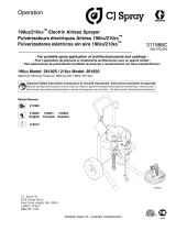
Assembly Drawing
1
2
4
1a
18
1b
31
8
48
48a
10b
10
5
5a
5b
22
9
12 10b
13
13a
10d
16 16a
10c
6
22a
ti28518a
Ref Description
1 Pump
1a Piston
1b Pad, foam
2Drive
4 Screw, drive
5 Motor
5a Fan Cover
5b Motor Screw
6Frame
8 Pressure Control
9 Left Shroud
10 Right Shroud
10b Screw, shroud
Ref Description
10c Clip, shroud (X7/LTS 17 only)
10d Screw, underside shroud (X7/LTS 17 only)
12 Switch, ON/OFF
13 Control Board Assembly
13a Screw, control board
16 Front Cover
16a Screw, front cover
18 Gear Cover
22 Power Cord
22a Screw, ground
31 Indicator, pressure control
48 PushPrime
48a Button, PushPrime

Replacement Procedures
3A3655A 3
Enclosure Disassembly
1. Unplug power cord (22) and perform Pressure
Relief Procedure, page 1, or see Owners manual
3A3208 or 3A3529.
2. Remove front cover screws (16a) (T-30 Torx).
3. X7 and LTS 17 only: Remove underside shroud
screw (10d).
4. Remove side shroud screws (10b) (T-20 Torx), and
remove right shroud (10).
5. Disconnect all wire leads and connectors from
control board (13).
6. Remove left shroud (9) and front cover (16).
Replacement Procedures
1. Proceed to the appropriate page for the replace-
ment kit instructions, as follows:
PushPrime Replacement, page 3
Control Board Replacement, page 4
Motor Replacement, page 4
Pump Assembly Replacement, page 5
2. Refer to the illustrations in the Assembly Drawing,
page 2, and in the Owners manual for additional
parts information, wiring diagrams, and any addi-
tional assembly torques.
PushPrime Replacement
To replace the PushPrime, first disassemble the
enclosure. See Enclosure Disassembly, page 3.
1. Using a 1/16" hex driver, remove button (48a) by
loosening set screw.
2. Using a 13mm deep socket, remove PushPrime
module (48).
3. Install replacement PushPrime module (48). Torque
to 200-220 in-lb.
4. Install button (48a) by lightly tightening set screw.
5. Perform Enclosure Assembly, page 6
ELECTRICAL SHOCK HAZARD
MOVING PARTS HAZARD
To reduce risk of serious injury, do not touch electrical
or moving parts with fingers or tools while testing
repair. Unplug sprayer when power is not required for
testing. Install all covers, gaskets, screws and washers
before you operate sprayer.

Replacement Procedures
4 3A3655A
Control Board Replacement
To replace the control board, first disassemble the
enclosure. See Enclosure Disassembly, page 3.
1. Remove control board mounting screw (13a) and
control board (13) from left side shroud (9).
2. If needed, assemble replacement control board into
bracket.
3. Install control board assembly (13) to left side
shroud (9) with mounting screw (13a).Torque to
12-16 in-lb.
4. Perform Enclosure Assembly, page 6.
Motor Replacement
To replace the motor, you must first disassemble the
enclosure. See Enclosure Disassembly, page 3.
1. Disconnect motor leads from control board (13) and
power cord (22).
2. Remove fan cover (5a) by gently prying adjacent to
its narrow retention bars with a flat blade screw-
driver. NOTE: Prying on the bars themselves can
cause damage.
3. Remove 2 motor screws (5b) (T-20 Torx). Pull motor
(5) from the pump/drive assembly. Be careful not to
damage the cooling fan.
4. Assemble replacement motor (5) to the drive (2)
with the black wire lead on the pressure control (8)
side of the sprayer. Install 2 motor screws (5b) (T-20
Torx). Torque to 26-32 in-lb.
5. Route the motor leads through the ports in the fan
cover (5a). Snap the cover onto the motor (5).
6. Perform Enclosure Assembly, page 6.

Replacement Procedures
3A3655A 5
Pump Assembly Replacement
To replace the pump assembly, first disassemble the
enclosure. See Enclosure Disassembly, page 3.
1. Remove suction hose and drain tube from pump (1).
2. Loosen screw (22a) retaining the green ground wire
to the back of the drive (2) and remove the ground
wire.
3. Remove fan cover (5a) by gently prying adjacent to
its narrow retention bars with a flat blade
screwdriver. NOTE: Prying on the bars themselves
can cause damage.
4. Remove 2 motor screws (5b) (T-20 Torx). Pull motor
(5) from the pump/drive assembly. Be careful not to
damage the cooling fan.
5. Remove gear cover (18). Remove the two screws
(4) at the bottom of the pump/drive assembly then
remove the pump/drive assembly.
6. Place the pump/drive assembly in a vise with the
jaws clamping on the flat sides at the bottom of the
pump (1).
7. Open the latch at the bottom of the setting indicator
(31), remove it from the pressure control (8).
8. Remove the two screws (4) holding the drive (2) to
the pump (1), then rotate the drive bracket
approximately 90°.
9. Pull the drive assembly (2) and pump piston (1a)
from the pump (1). If necessary, tap on the shorter
leg of the drive with a plastic hammer to separate
the parts. NOTE: Prying between the pump and the
drive can damage the drive and lead to failure of
equipment.
10. Verify that a small amount of grease has been
applied to the drive pocket in the pump piston (1a) in
the replacement pump (1).
11. Rotate the drive gear to bring the stud towards the
pump, then insert the stud into the piston pocket.
Align the drive shaft with the pump bushing, then
push the drive into the pump, rotating the gear to
draw the drive inward. Press the drive and pump
fully together. If necessary, tap on the bottom of the
drive with a plastic hammer to seat the piston in the
pump.
12. Install two screws (4) at the top of the drive (2).
Torque to 80-90 in-lb.
13. Assemble motor (5) to the drive (2) with the black
wire lead on the pressure control (8) side of the
sprayer. Install 2 motor screws (5b) (T-20 Torx).
Torque to 26-32 in-lb.
14. Route the motor leads through the ports in the fan
cover (5a). Snap the cover onto the motor (5).
15. Replace foam pad (1b) on frame (6).
16. Place the pump/drive/motor assembly on the
sprayer frame (6), then install the two screws (4) at
the bottom of the drive (2). Torque to 80-90 in-lb.
17. Reassemble gear cover (18).
18. Route the pressure control wire harness through the
setting indicator (31). Install the indicator around the
pressure control (8), snap together. Pass the wire
harness through the front cover (16), aligning the
indicator with the opening in front cover as they are
positioned loosely on the pump.
19. Attach green ground wire to back of the drive
assembly (2) using screw (22a). Torque to 25-35
in-lb.
20. Replace the suction and drain hoses on the pump
(1), and secure with their clamps
21. Perform Enclosure Assembly, page 6

Replacement Procedures
6 3A3655A
Enclosure Assembly
1. Reassemble left shroud (9) and front cover (16).
2. Install power cord (22) into recess on left shroud (9).
3. Reconnect all wire leads and connectors, see
Wiring Diagram, page 7.
4. After power cord connections are made, twist cord
two or three times to group wires by removing slack.
Then place cord grip in shroud location. Pay special
attention to ensure wires are free from the area
surrounding the motor rotor.
5. Reassemble right shroud (10). Verify no wire leads
are pinched between the shroud, motor and
pump/drive assembly.
6. Install side shroud screws (10b) (T-20 Torx). Torque
to 20-25 in-lb.
7. X7 and LTS 17 only: Install underside shroud
screw (10d).Torque to 25-35 in-lb.
8. Install front cover screws (16a) (T-30 Torx). Torque
to 36-42 in-lb.
9. Perform AssemblyVerification, page 6.
AssemblyVerification
After assembly is complete, perform the following steps
to verify proper operation. If sprayer fails one of the
steps, repeat Enclosure Disassembly, page 3, and
Replacement Procedures, page 3.
1. Visually inspect for gaps between enclosure halves.
A gap larger than 1/32 in. (0.8 mm) may be caused
by a pinched wire or an internal component not
seated properly. If disassembly and inspection
indicates that no wire has been pinched and all
internal components are seated properly, carefully
reassemble and repeat verification steps.
2. Turn prime/spray valve to make sure it rotates
forward to the spray position and down to the prime
position.
3. Turn pressure control knob to verify it rotates.
4. Using water, verify sprayer primes and sprays.
Follow instructions in sprayer Operation manual for
proper setup, priming and spraying procedures. See
Owners manual 3A3208 or 3A3529.
ELECTRICAL SHOCK HAZARD
MOVING PARTS HAZARD
To reduce risk of serious injury, do not touch electrical
or moving parts with fingers or tools while testing
repair. Unplug sprayer when power is not required for
testing. Install all covers, gaskets, screws and washers
before you operate sprayer.

Replacement Procedures
3A3655A 7
Wiring Diagram
GREEN
ON/OFF
SWITCH
WHITE
BLACK
PRESSURE SWITCH
WHITE
BLACK
MOTOR
ti14050a

All written and visual data contained in this document reflects the latest product information available at the time of publication.
Graco reserves the right to make changes at any time without notice.
For patent information, see www.graco.com/patents.
2ULJLQDOLQVWUXFWLRQV This manual contains English. MM 3A3655
Graco Headquarters: Minneapolis
International Offices: Belgium, China, Japan, Korea
GRACO INC. AND SUBSIDIARIES • P.O. BOX 1441 • MINNEAPOLIS MN 55440-1441 • USA
Copyright 2016, Graco Inc. All Graco manufacturing locations are registered to ISO 9001.
www.graco.com
Revision A,April 2016
/