Gigabyte GA-G31M-ES2C User manual
- Category
- Motherboards
- Type
- User manual
This manual is also suitable for

GA-G31M-ES2L
GA-G31M-ES2C
LGA775 socket motherboard for Intel
®
Core
™
processor family/
Intel
®
Pentium
™
processor family/Intel
®
Celeron
™
processor family
User's Manual
Rev. 2401
12ME-G31MES2L-2401R

Motherboard
GA-G31M-ES2L
GA-G31M-ES2C
May 20, 2010
May 20, 2010
Motherboard
GA-G31M-ES2L/GA-G31M-ES2C

Copyright
© 2010 GIGA-BYTE TECHNOLOGY CO., LTD. All rights reserved.
The trademarks mentioned in this manual are legally registered to their respective owners.
Disclaimer
Information in this manual is protected by copyright laws and is the property of GIGABYTE.
Changes to the specifications and features in this manual may be made by GIGABYTE
without prior notice. No part of this manual may be reproduced, copied, translated, transmitted,
or published in any form or by any means without GIGABYTE's prior written permission.
Documentation Classications
In order to assist in the use of this product, GIGABYTE provides the following types of documentations:
For detailed product information, carefully read the User's Manual.
For instructions on how to use GIGABYTE's unique features, read or download the information
on/from the Support&Downloads\Motherboard\Technology Guide page on our website.
For product-related information, check on our website at:
http://www.gigabyte.com
Identifying Your Motherboard Revision
The revision number on your motherboard looks like this: "REV: X.X." For example, "REV: 1.0"
means the revision of the motherboard is 1.0. Check your motherboard revision before updating
motherboard BIOS, drivers, or when looking for technical information.
Example:

- 4 -
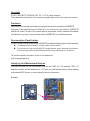
Table of Contents
GA-G31M-ES2L/GA-G31M-ES2C Motherboard Layout .................................................5
Chapter 1 Hardware Installation .....................................................................................6
1-1 Installation Precautions ................................................................................... 6
1-2 ProductSpecications ..................................................................................... 7
1-3 Installing the CPU and CPU Cooler................................................................. 9
1-3-1 Installing the CPU ....................................................................................................9
1-4 Installing the Memory .................................................................................... 10
1-4-1 DualChannelMemoryConguration ....................................................................10
1-5 Installing an Expansion Card ......................................................................... 10
1-6 Back Panel Connectors ..................................................................................11
1-7 Internal Connectors ....................................................................................... 13
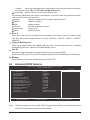
Chapter 2 BIOS Setup ..................................................................................................22
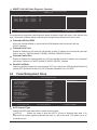
2-1 Startup Screen ............................................................................................... 22
2-2 The Main Menu .............................................................................................. 22
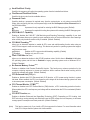
2-3 Standard CMOS Features ............................................................................. 23
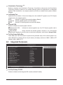
2-4 Advanced BIOS Features .............................................................................. 24
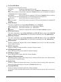
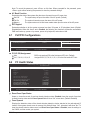
2-5 Integrated Peripherals ................................................................................... 26
2-6 Power Management Setup ............................................................................ 28
2-7 PnP/PCICongurations ................................................................................. 30
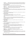
2-8 PC Health Status ........................................................................................... 30
2-9 MB Intelligent Tweaker(M.I.T.) ....................................................................... 31
2-10 Load Fail-Safe Defaults ................................................................................. 33
2-11 Load Optimized Defaults ............................................................................... 33
2-12 Set Supervisor/User Password ..................................................................... 34
2-13 Save & Exit Setup .......................................................................................... 34
2-14 Exit Without Saving........................................................................................ 35
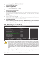
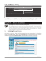
Chapter 3 Drivers Installation .......................................................................................35
3-1 Installing Chipset Drivers ............................................................................... 35
Regulatory Statements ..................................................................................................36

- 5 -
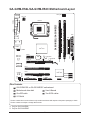
GA-G31M-ES2L/GA-G31M-ES2C Motherboard Layout
KB_MS
CPU_FAN
LGA775
ATX
GA-G31M-ES2L/GA-G31M-ES2C
CD_IN
F_AUDIO
AUDIO
B_BIOS
PCIE_1
CI
DDRII2
DDRII1
BAT
F_PANEL
ATX_12V
Intel
®
G31
Intel
®
ICH7
SATAII1
SATAII3
SATAII0
SATAII2
PCI1
CODEC
IDE
CLR_CMOS
M_BIOS
COMA
VGA
USB
PCIE_16
SPDIF_O
F_USB1
F_USB2
SYS_FAN
FDD
AR8131
j
AR8132
k
iTE
IT8718
R_USB
LAN
PWR_LED
PCI2
Box Contents
GA-G31M-ES2L or GA-G31M-ES2C motherboard
Motherboard driver disk User's Manual
One IDE cable Two SATA cables
I/O Shield
The box contents above are for reference only and the actual items shall depend on the product package you obtain.
The box contents are subject to change without notice.
j
Only for GA-G31M-ES2L.
k
Only for GA-G31M-ES2C.

Hardware Installation - 6 -
1-1 Installation Precautions
The motherboard contains numerous delicate electronic circuits and components which can
become damaged as a result of electrostatic discharge (ESD). Prior to installation, carefully read
the user's manual and follow these procedures:
• Prior to installation, do not remove or break motherboard S/N (Serial Number) sticker or
warranty sticker provided by your dealer. These stickers are required for warranty validation.
• Always remove the AC power by unplugging the power cord from the power outlet before
installing or removing the motherboard or other hardware components.
• When connecting hardware components to the internal connectors on the motherboard,
make sure they are connected tightly and securely.
• When handling the motherboard, avoid touching any metal leads or connectors.
• It is best to wear an electrostatic discharge (ESD) wrist strap when handling electronic com-
ponents such as a motherboard, CPU or memory. If you do not have an ESD wrist strap,
keepyourhandsdryandrsttouchametalobjecttoeliminatestaticelectricity.
•
Prior to installing the motherboard, please have it on top of an antistatic pad or within an
electrostatic shielding container.
• Before unplugging the power supply cable from the motherboard, make sure the power sup-
ply has been turned off.
• Before turning on the power, make sure the power supply voltage has been set according to
the local voltage standard.
• Before using the product, please verify that all cables and power connectors of your hard-
ware components are connected.
• To prevent damage to the motherboard, do not allow screws to come in contact with the
motherboard circuit or its components.
• Make sure there are no leftover screws or metal components placed on the motherboard or
within the computer casing.
• Do not place the computer system on an uneven surface
.
• Do not place the computer system in a high-temperature environment.
• Turning on the computer power during the installation process can lead to damage to sys-
tem components as well as physical harm to the user.
• If you are uncertain about any installation steps or have a problem related to the use of the
product,pleaseconsultacertiedcomputertechnician.
Chapter 1 Hardware Installation

- 7 - Hardware Installation
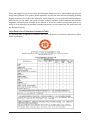
1-2 Product Specications
j
Only for GA-G31M-ES2L.
k
Only for GA-G31M-ES2C.
CPU
w
Support for an Intel
®
Core
™
2 Extreme processor/Intel
®
Core
™
2 Quad processor/
Intel
®
Core
™
2 Duo processor/Intel
®
Pentium
®
processor/Intel
®
Celeron
®
processor
in the LGA 775 package
(Go to GIGABYTE's website for the latest CPU support list.)
w
L2 cache varies with CPU
Front Side Bus
w
1333/1066/800 MHz FSB
Chipset
w
North Bridge: Intel
®
G31 Express Chipset
w
South Bridge: Intel
®
ICH7
Memory
w
2 x 1.8V DDR2 DIMM sockets supporting up to 4 GB of system memory
(Note 1)
w
Dual channel memory architecture
w
Support for DDR2 800/667 MHz memory modules
(Go to GIGABYTE's website for the latest supported memory speeds and
memory modules.)
Onboard Graphics
w
Integrated in the North Bridge:
- 1 x D-Sub port
Audio
w
Realtek ALC883/888B codec
w
HighDenitionAudio
w
2/4/5.1/7.1-channel
(Note 2)
w
Support for S/PDIF Out
w
Support for CD In
LAN
w
AR8131 chip (10/100/1000 Mbit)
j
w
AR8132 chip (10/100 Mbit)
k
Expansion Slots
w
1 x PCI Express x16 slot
w
1 x PCI Express x1 slot
w
2 x PCI slots
Storage Interface
w
South Bridge:
- 1 x IDE connector supporting ATA-100/66/33 and up to 2 IDE devices
- 4 x SATA 3Gb/s connectors supporting up to 4 SATA 3Gb/s devices
w
iTE IT8718 chip:
- 1xoppydiskdriveconnectorsupportingupto1oppydiskdrive
USB
w
South Bridge:
- Up to 8 USB 2.0/1.1 ports (4 on the back panel, 4 via the USB brackets
connected to the internal USB headers)
Internal
w
1 x 24-pin ATX main power connector
Connectors
w
1 x 4-pin ATX 12V power connector
w
1xoppydiskdriveconnector
w
1 x IDE connector
w
4 x SATA 3Gb/s connectors
w
1 x CPU fan header
w
1 x system fan header

Hardware Installation - 8 -
Internal
w
1 x front panel header
Connectors
w
1 x front panel audio header
w
1 x CD In connector
w
1 x S/PDIF Out header
w
2 x USB 2.0/1.1 headers
w
1 x power LED header
w
1 x chassis intrusion header
Back Panel
w
1 x PS/2 keyboard port
Connectors
w
1 x PS/2 mouse port
w
1 x parallel port
w
1 x serial port
w
1 x D-Sub port
w
4 x USB 2.0/1.1 ports
w
1 x RJ-45 port
w
3 x audio jacks (Line In/Line Out/Microphone)
I/O
w
iTE IT8718
Hardware Monitor
w
System voltage detection
w
CPU temperature detection
w
CPU/System fan speed detection
w
CPU overheating warning
w
CPU/System fan fail warning
w
CPU fan speed control
(Note 3)
BIOS
w
2x4Mbitash
w
Use of licensed AWARD BIOS
w
Support for DualBIOS
™
w
PnP 1.0a, DMI 2.0, SM BIOS 2.4, ACPI 1.0b
Unique Features
w
Support for @BIOS
w
Support for Q-Flash
w
Support for Xpress BIOS Rescue
w
Support for Download Center
w
Support for Xpress Install
w
Support for Xpress Recovery2
w
Support for EasyTune
(Note 4)
w
Support for Easy Energy Saver
(Note 5)
w
Support for Time Repair
w
Support for ON/OFF Charge
w
Support for Q-Share
Bundled Software
w
Norton Internet Security (OEM version)
Operating System
w
Support for Microsoft
®
Windows
®
7/Vista/XP
Form Factor
w
Micro ATX form factor; 24.4cm x 19.4cm

- 9 - Hardware Installation
(Note 1) Based on standard PC architecture, a certain amount of memory is reserved for system usage and
therefore the actual memory size is less than the stated amount. For example, 4 GB of memory size
will instead be shown as 3.xx GB during system startup.
(Note2) Tocongure7.1-channelaudio,youneedconnectwiththeportofHDAudiostandardviafront
panel and enable the multi-channel audio feature through the audio driver.
(Note 3) Whether the CPU fan speed control function is supported will depend on the CPU you install.
(Note 4) Available functions in EasyTune may differ by motherboard model.
(Note 5) Due to the hardware limitation, you must install the Intel
®
Core
™
2 Extreme/Core
™
2 Quad/
Core
™
2 Duo/Pentium Dual-Core/Celeron Dual-Core/Celeron 400 Series CPU to enable support for
Easy Energy Saver
1-3 Installing the CPU and CPU Cooler
Read the following guidelines before you begin to install the CPU:
• Make sure that the motherboard supports the CPU.
(Go to GIGABYTE's website for the latest CPU support list.)
• Always turn off the computer and unplug the power cord from the power outlet before installing
the CPU to prevent hardware damage.
• Locate the pin one of the CPU. The CPU cannot be inserted if oriented incorrectly. (Or you may
locate the notches on both sides of the CPU and alignment keys on the CPU socket.)
• Apply an even and thin layer of thermal grease on the surface of the CPU.
• Do not turn on the computer if the CPU cooler is not installed, otherwise overheating and dam-
age of the CPU may occur.
• SettheCPUhostfrequencyinaccordancewiththeCPUspecications.Itisnotrecommended
thatthesystembusfrequencybesetbeyondhardwarespecicationssinceitdoesnotmeetthe
standard requirements for the peripherals. If you wish to set the frequency beyond the standard
specications,pleasedosoaccordingtoyourhardwarespecicationsincludingtheCPU,graph-
ics card, memory, hard drive, etc.
1-3-1 Installing the CPU
A. Locate the alignment keys on the motherboard CPU socket and the notches on the CPU.
Notch
Notch
Alignment Key
Alignment Key
LGA775 CPU
LGA775 CPU Socket
Pin One Corner of the CPU Socket
Triangle Pin One Marking on the CPU

Hardware Installation - 10 -
1-4 Installing the Memory
Read the following guidelines before you begin to install the memory:
• Make sure that the motherboard supports the memory. It is recommended that memory of the
same capacity, brand, speed, and chips be used.
(Go to GIGABYTE's website for the latest supported memory speeds and memory modules.)
• Always turn off the computer and unplug the power cord from the power outlet before installing
the memory to prevent hardware damage.
• Memory modules have a foolproof design. A memory module can be installed in only one direc-
tion. If you are unable to insert the memory, switch the direction.
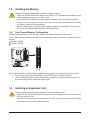
1-4-1 Dual Channel Memory Conguration
This motherboard provides two DDR2 memory sockets and supports Dual Channel Technology.
The two DDR2 memory sockets are divided into two channels and each channel has one memory socket as
following:
Channel 0: DDRII1
Channel 1: DDRII2
DDRII1
DDRII2
Due to chipset limitation, read the following guidelines before installing the memory in Dual Channel mode.
1. Dual Channel mode cannot be enabled if only one DDR2 memory module is installed.
2. When enabling Dual Channel mode with two memory modules, it is recommended that memory of
the same capacity, brand, speed, and chips be used.
1-5 Installing an Expansion Card
Read the following guidelines before you begin to install an expansion card:
• Make sure the motherboard supports the expansion card. Carefully read the manual that came
with your expansion card.
• Always turn off the computer and unplug the power cord from the power outlet before installing
an expansion card to prevent hardware damage.

- 11 - Hardware Installation
1-6 Back Panel Connectors
PS/2 Keyboard and PS/2 Mouse Port
Use the upper port (green) to connect a PS/2 mouse and the lower port (purple) to connect a PS/2
keyboard.
Parallel Port
Use the parallel port to connect devices such as a printer, scanner and etc. The parallel port is also
called a printer port.
Serial Port
Use the serial port to connect devices such as a mouse, modem or other peripherals.
D-Sub Port
The D-Sub port supports a 15-pin D-Sub connector. Connect a monitor that supports D-Sub connection
to this port.
USB 2.0/1.1 Port
TheUSBportsupportstheUSB2.0/1.1specication.UsethisportforUSBdevicessuchasaUSBkey-
board/mouse,USBprinter,USBashdriveandetc.
RJ-45 LAN Port
j
The Gigabit Ethernet LAN port provides Internet connection at up to 1 Gbps data rate. The following
describes the states of the LAN port LEDs.
Activity LED:
State Description
Blinking Data transmission or receiving is occurring
Off No data transmission or receiving is occurring
Connection/Speed LED:
State Description
Orange 1 Gbps data rate
Green 100 Mbps data rate
Off 10 Mbps data rate
Activity LED
Connection/
Speed LED
LAN Port
RJ-45 LAN Port
k
The Fast Ethernet LAN port provides Internet connection at up to 100 Mbps data rate. The following de-
scribes the states of the LAN port LEDs.
Activity LED:
State Description
Blinking Data transmission or receiving is occurring
Off No data transmission or receiving is occurring
Connection LED:
State Description
On LAN link is established
Off LAN link is not established
Activity LEDConnection LED
LAN Port
j
Only for GA-G31M-ES2L.
k
Only for GA-G31M-ES2C.

Hardware Installation - 12 -
Line In Jack (Blue)
The default line in jack. Use this audio jack for line in devices such as an optical drive, walkman, etc.
Line Out Jack (Green)
The default line out jack. Use this audio jack for a headphone or 2-channel speaker. This jack can be
usedtoconnectfrontspeakersina4/5.1-channelaudioconguration.
Mic In Jack (Pink)
The default Mic in jack. Microphones must be connected to this jack.
• Whenremovingthecableconnectedtoabackpanelconnector,rstremovethecablefromyour
device and then remove it from the motherboard.
• When removing the cable, pull it straight out from the connector. Do not rock it side to side to
prevent an electrical short inside the cable connector.

- 13 - Hardware Installation
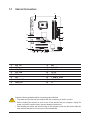
1-7 Internal Connectors
Read the following guidelines before connecting external devices:
• First make sure your devices are compliant with the connectors you wish to connect.
• Before installing the devices, be sure to turn off the devices and your computer. Unplug the
power cord from the power outlet to prevent damage to the devices.
• After installing the device and before turning on the computer, make sure the device cable has
been securely attached to the connector on the motherboard.
1
6
3
2
7
1645 14
11
15
9
12
8
10
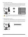
1) ATX_12V
2) ATX
3) CPU_FAN
4) SYS_FAN
5) FDD
6) IDE
7) SATAII0/1/2/3
8) PWR_LED
9) BAT
10) F_PANEL
11) F_AUDIO
12) CD_IN
13) SPDIF_O
14) F_USB1/F_USB2
15) CLR_CMOS
16) CI
13

Hardware Installation - 14 -
ATX_12V:
ATX_12V
1
3
2
4
DEBUG
PORT
G.QBOFM
131
2412
ATX
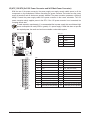
ATX:
PinNo. Denition
13 3.3V
14 -12V
15 GND
16 PS_ON (soft On/Off)
17 GND
18 GND
19 GND
20 -5V
21 +5V
22 +5V
23 +5V (Only for 2x12-pin ATX)
24 GND (Only for 2x12-pin ATX)
PinNo. Denition
1 3.3V
2 3.3V
3 GND
4 +5V
5 GND
6 +5V
7 GND
8 Power Good
9 5VSB (stand by +5V)
10 +12V
11 +12V (Only for 2x12-pin ATX)
12 3.3V (Only for 2x12-pin ATX)
1/2) ATX_12V/ATX (2x2 12V Power Connector and 2x12 Main Power Connector)
With the use of the power connector, the power supply can supply enough stable power to all the
components on the motherboard. Before connecting the powerconnector,rstmakesure the power
supply is turned off and all devices are properly installed. The power connector possesses a foolproof
design. Connect the power supply cable to the power connector in the correct orientation. The 12V
power connector mainly supplies power to the CPU. If the 12V power connector is not connected, the
computer will not start.
PinNo. Denition
1 GND
2 GND
3 +12V
4 +12V
To meet expansion requirements, it is recommended that a power supply that can withstand high
power consumption be used (500W or greater). If a power supply is used that does not provide
the required power, the result can lead to an unstable or unbootable system.

- 15 - Hardware Installation
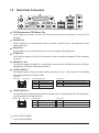
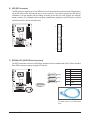
3/4) CPU_FAN/SYS_FAN (Fan Headers)
The motherboard has a 4-pin CPU fan header (CPU_FAN) and a 3-pin (SYS_FAN) system fan header.
Most fan headers possess a foolproof insertion design. When connecting a fan cable, be sure to connect
it in the correct orientation (the black connector wire is the ground wire). The motherboard supports CPU
fan speed control, which requires the use of a CPU fan with fan speed control design. For optimum heat
dissipation, it is recommended that a system fan be installed inside the chassis.
CPU_FAN
DEBUG
PORT
G.QBOFM
SYS_FAN
1
1
CPU_FAN:
PinNo. Denition
1 GND
2 +12V / Speed Control
3 Sense
4 Speed Control
SYS_FAN:
PinNo. Denition
1 GND
2 +12V
3 Sense
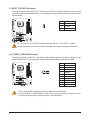
5) FDD (Floppy Disk Drive Connector)
Thisconnector isusedto connect aoppy disk drive.The typesofoppy diskdrivessupported are:
360KB,720KB,1.2MB,1.44MB,and2.88MB.Beforeconnectingaoppydiskdrive,besuretolocate
pin1oftheconnectorandtheoppydiskdrivecable.Thepin1ofthecableistypicallydesignatedbya
stripeofdifferentcolor.Forpurchasingtheoptionaloppydiskdrivecable,pleasecontactthelocaldealer.
1
2
33
34
• Be sure to connect fan cables to the fan headers to prevent your CPU and system from over-
heating. Overheating may result in damage to the CPU or the system may hang.
• These fan headers arenotconguration jumper blocks.Donotplace a jumper cap on the
headers.
DEBUG
PORT
G.QBOFM

Hardware Installation - 16 -
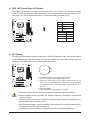
6) IDE (IDE Connector)
The IDE connector supports up to two IDE devices such as hard drives and optical drives. Before attach-
ing the IDE cable, locate the foolproof groove on the connector. If you wish to connect two IDE devices,
remember to set the jumpers and the cabling according to the role of the IDE devices (for example,
masterorslave).(Forinformationaboutconguringmaster/slavesettingsfortheIDEdevices,readthe
instructions from the device manufacturers.)
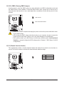
7) SATAII0/1/2/3 (SATA 3Gb/s Connectors)
The SATA connectors conform to SATA 3Gb/s standard and are compatible with SATA 1.5Gb/s standard.
Each SATA connector supports a single SATA device.
17
7 1
PinNo. Denition
1 GND
2 TXP
3 TXN
4 GND
5 RXN
6 RXP
7 GND
DEBUG
PORT
G.QBOFM
DEBUG
PORT
G.QBOFM
SATAII3
SATAII2
SATAII1
SATAII0
2
40
1
39
Please connect the L-shaped end of
the SATA cable to your SATA hard
drive.
DEBUG
PORT
G.QBOFM
DEBUG
PORT
G.QBOFM

- 17 - Hardware Installation
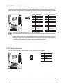
8) PWR_LED (System Power LED Header)
This header can be used to connect a system power LED on the chassis to indicate system power
status. The LED is on when the system is operating. The LED keeps blinking when the system is in S1
sleep state. The LED is off when the system is in S3/S4 sleep state or powered off (S5).
1
PinNo. Denition
1 MPD+
2 MPD-
3 MPD-
System Status LED
S0 On
S1 Blinking
S3/S4/S5 Off
9) BAT (Battery)
Thebatteryprovidespowertokeepthevalues(suchasBIOScongurations,date,andtimeinformation)
in the CMOS when the computer is turned off. Replace the battery when the battery voltage drops to a
low level, or the CMOS values may not be accurate or may be lost.
You may clear the CMOS values by removing the battery:
1. Turn off your computer and unplug the power cord.
2. Gently remove the battery from the battery holder and wait for one
minute. (Or use a metal object like a screwdriver to touch the positive
and negative terminals of the battery holder, making them short for 5
seconds.)
3. Replace the battery.
4. Plug in the power cord and restart your computer.
• Always turn off your computer and unplug the power cord before replacing the battery.
• Replace the battery with an equivalent one. Danger of explosion if the battery is replaced with
an incorrect model.
• Contact the place of purchase or local dealer if you are not able to replace the battery by your-
self or uncertain about the battery model.
• When installing the battery, note the orientation of the positive side (+) and the negative side (-)
of the battery (the positive side should face up).
• Used batteries must be handled in accordance with local environmental regulations.

Hardware Installation - 18 -
10) F_PANEL (Front Panel Header)
Connect the power switch, reset switch, speaker and system status indicator on the chassis front panel
to this header according to the pin assignments below. Note the positive and negative pins before con-
necting the cables.
• PW (Power Switch):
Connectstothepowerswitchonthechassisfrontpanel.Youmaycongurethewaytoturnoffyour
system using the power switch (refer to Chapter 2, "BIOS Setup," "Power Management Setup," for
more information).
• SPEAK (Speaker):
Connects to the speaker on the chassis front panel. The system reports system startup status by is-
suing a beep code. One single short beep will be heard if no problem is detected at system startup. If
a problem is detected, the BIOS may issue beeps in different patterns to indicate the problem.
• HD (Hard Drive Activity LED)
Connects to the hard drive activity LED on the chassis front panel. The LED is on when the hard drive
is reading or writing data.
• RES (Reset Switch):
Connects to the reset switch on the chassis front panel. Press the reset switch to restart the computer
if the computer freezes and fails to perform a normal restart.
• NC:
No connection
• MSG (Message/Power/Sleep LED):
Connects to the power status indicator on the chassis front panel. The LED
is on when the system is operating. The LED keeps blinking when the sys-
tem is in S1 sleep state. The LED is off when the system is in S3/S4 sleep
state or powered off (S5).
System Status LED
S0 On
S1 Blinking
S3/S4/S5 Off
The front panel design may differ by chassis. A front panel module mainly consists of power
switch, reset switch, power LED, hard drive activity LED, speaker and etc. When connecting your
chassis front panel module to this header, make sure the wire assignments and the pin assign-
ments are matched correctly.
1
2
1920
NC
MSG-
PW-
SPEAK+
SPEAK-
MSG+
PW+
Message/Power/
Sleep LED
Speaker
Power
Switch
HD-
RES+
HD+
RES-
Hard Drive
Activity LED
Reset
Switch

- 19 - Hardware Installation
11) F_AUDIO (Front Panel Audio Header)
ThefrontpanelaudioheadersupportsIntelHighDenitionaudio(HD)andAC'97audio.Youmayconnect
your chassis front panel audio module to this header. Make sure the wire assignments of the module con-
nector match the pin assignments of the motherboard header. Incorrect connection between the module
connector and the motherboard header will make the device unable to work or even damage it.
PinNo. Denition
1 MIC2_L
2 GND
3 MIC2_R
4 -ACZ_DET
5 LINE2_R
6 GND
7 FAUDIO_JD
8 No Pin
9 LINE2_L
10 GND
PinNo. Denition
1 MIC
2 GND
3 MIC Power
4 NC
5 Line Out (R)
6 NC
7 NC
8 No Pin
9 Line Out (L)
10 NC
For HD Front Panel Audio: For AC'97 Front Panel Audio:
12) CD_IN (CD In Connector)
You may connect the audio cable that came with your optical drive to the header.
PinNo. Denition
1 CD-L
2 GND
3 GND
4 CD-R
• The front panel audio header supports HD audio by default.
• Audio signals will be present on both of the front and back panel audio connections simultane-
ously.
• Some chassis provide a front panel audio module that has separated connectors on each wire
instead of a single plug. For information about connecting the front panel audio module that
has different wire assignments, please contact the chassis manufacturer.
2 10
1 9
1

Hardware Installation - 20 -
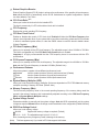
13) SPDIF_O (S/PDIF Out Header)
This header supports digital S/PDIF out. Via an optional S/PDIF out cable, this header can connect to an
audio device that supports digital audio in. For purchasing the optional S/PDIF out cable, please contact
the local dealer.
PinNo. Denition
1 Power
2 SPDIFO
3 GND
1
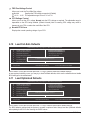
14) F_USB1/F_USB2 (USB Headers)
TheheadersconformtoUSB2.0/1.1specication.EachUSBheadercanprovidetwoUSBportsviaan
optional USB bracket. For purchasing the optional USB bracket, please contact the local dealer.
PinNo. Denition
1 Power (5V)
2 Power (5V)
3 USB DX-
4 USB DY-
5 USB DX+
6 USB DY+
7 GND
8 GND
9 No Pin
10 NC
• Do not plug the IEEE 1394 bracket (2x5-pin) cable into the USB header.
• Prior to installing the USB bracket, be sure to turn off your computer and unplug the power
cord from the power outlet to prevent damage to the USB bracket.
10
9
2
1
Pin 1 (the red wire) of the S/PDIF out cable must align with pin 1 of the SPDIF_O header.
Incorrect connection may render the device unusable or even result in damage to the device.
Page is loading ...
Page is loading ...
Page is loading ...
Page is loading ...
Page is loading ...
Page is loading ...
Page is loading ...
Page is loading ...
Page is loading ...
Page is loading ...
Page is loading ...
Page is loading ...
Page is loading ...
Page is loading ...
Page is loading ...
Page is loading ...
Page is loading ...
Page is loading ...
Page is loading ...
Page is loading ...
-
 1
1
-
 2
2
-
 3
3
-
 4
4
-
 5
5
-
 6
6
-
 7
7
-
 8
8
-
 9
9
-
 10
10
-
 11
11
-
 12
12
-
 13
13
-
 14
14
-
 15
15
-
 16
16
-
 17
17
-
 18
18
-
 19
19
-
 20
20
-
 21
21
-
 22
22
-
 23
23
-
 24
24
-
 25
25
-
 26
26
-
 27
27
-
 28
28
-
 29
29
-
 30
30
-
 31
31
-
 32
32
-
 33
33
-
 34
34
-
 35
35
-
 36
36
-
 37
37
-
 38
38
-
 39
39
-
 40
40


Gigabyte GA-G31M-ES2C User manual
- Category
- Motherboards
- Type
- User manual
- This manual is also suitable for
Ask a question and I''ll find the answer in the document
Finding information in a document is now easier with AI
Related papers
-
Gigabyte GA-G31MX-S2 User manual
-
Gigabyte GA-G31M-ES2L User manual
-
-
-
Gigabyte GA-946GMX-S2 User manual
-
-
-
Gigabyte GA-GC330UD User manual
-
-
Gigabyte GA-M68M-S2P User manual
