PC CHIPS M791G (V1.0a) Specification
- Category
- Motherboards
- Type
- Specification
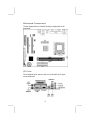
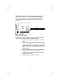
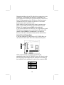
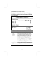
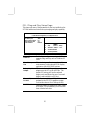
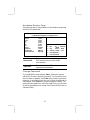
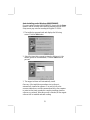
PC CHIPS M791G (V1.0a) is an ATX-form factor motherboard featuring VIA CLE266 Northbridge and 8235 Southbridge chipsets, supporting Socket-370 Intel Celeron, Pentium III, or VIA C3 Samuel 2 processors with up to 133MHz front-side bus, and offering a range of capabilities for building a multimedia workstation.
PC CHIPS M791G (V1.0a) is an ATX-form factor motherboard featuring VIA CLE266 Northbridge and 8235 Southbridge chipsets, supporting Socket-370 Intel Celeron, Pentium III, or VIA C3 Samuel 2 processors with up to 133MHz front-side bus, and offering a range of capabilities for building a multimedia workstation.


-
 1
1
-
 2
2
-
 3
3
-
 4
4
-
 5
5
-
 6
6
-
 7
7
-
 8
8
-
 9
9
-
 10
10
-
 11
11
-
 12
12
-
 13
13
-
 14
14
-
 15
15
-
 16
16
-
 17
17
-
 18
18
-
 19
19
-
 20
20
-
 21
21
-
 22
22
-
 23
23
-
 24
24
-
 25
25
-
 26
26
-
 27
27
-
 28
28
-
 29
29
-
 30
30
-
 31
31
-
 32
32
-
 33
33
-
 34
34
-
 35
35
-
 36
36
-
 37
37
-
 38
38


PC CHIPS M791G (V1.0a) Specification
- Category
- Motherboards
- Type
- Specification
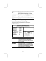
PC CHIPS M791G (V1.0a) is an ATX-form factor motherboard featuring VIA CLE266 Northbridge and 8235 Southbridge chipsets, supporting Socket-370 Intel Celeron, Pentium III, or VIA C3 Samuel 2 processors with up to 133MHz front-side bus, and offering a range of capabilities for building a multimedia workstation.
Ask a question and I''ll find the answer in the document
Finding information in a document is now easier with AI
Related papers
Other documents
-
Canyon CNR-USBHUB5N Datasheet
-
ECS K7S7AG User manual
-
Microsoft mainboard User manual
-
-
MATSONIC MS8177C Series User manual
-
-
-
-
-