
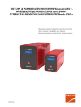
UNINTERRUPTIBLE POWER SUPPLY (UPS) + LIGHTING FLOW DIMMER STABILIZERS (ILUEST) + SWITCH MODE POWER SUPPLY + STATIC INVERTERS + PHOTOVOLTAIC INVERTERS + VOLTAGE STABILIZERS AND POWER LINE CONDITIONERS
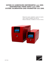
SPS SOHO+ series
USER’S MANUAL
UNINTERRUPTIBLE POWER SUPPLY


3
SALICRU
General index
1. Introduction.
1.1. Acknowledgement letter.
1.2. Using this manual.
1.2.1. Conventions and used symbols.
1.2.2. For more information and/or help.
1.2.3. Safety instructions.
1.2.3.1. General safety warnings.
1.2.3.2. To keep in mind.
1.2.3.3. Safety warning regarding batteries.
2. Quality and standard guarantee.
2.1. Declaration of the management.
2.2. Standard.
2.3. Environment.
3. Presentation.
3.1. Views.
3.1.1. Views of the equipment.
3.2. Synoptic with LCD display.
3.3. Nomenclature.
3.4. Structural diagram.
3.5. Operating principle.
4. Installation.
4.1. To be considered in the installation.
4.2. Equipment reception.
4.2.1. Unpacking and contents checking.
4.2.2. Storing.
4.2.3. Location.
4.2.4. Battery charging.
4.3. Communication ports.
4.3.1. Description and features.
4.3.2. Software.
4.4. Connection.
4.4.1. Power Supply connection.
4.4.2. Output connection.
4.4.3. Modem/Phoneline Connection.
5. OPERATION.
5.1. Preliminary controls.
5.2. Start up and shutdown.
5.3. LCD display.
6. Maintenance, warranty and service.
6.1. Basic maintenance guide.
6.2. Battery maintenance.
6.2.1. Notes for installing and replacing the batteries.
6.3. SPS troubleshooting guide.
6.4. Warranty conditions.
6.4.1. Covered product.
6.4.2. Warranty terms.
6.4.3. Out of scope of supply.
6.5. Technical service network.
7. Annexes.
7.1. General technical specifications.
7.2. Glossary.

4
SALICRU
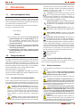
1. Introduction.
1.1. Acknowledgement letter.
We would like to thank you in advance for the trust you have
placed in us by purchasing this product. Read this instruction
manual carefully before starting up the equipment and keep it for
any possible future consult that can arise.
We remain at you entire disposal for any further information or
any query you should wish to make.
Yours sincerely.
The equipment here described can cause important
physical damages due to wrong handling. This is
why, the installation, maintenance and/or fixing of the
here described equipment must be done by our staff or
specifically authorised.
According to our policy of constant evolution, we reserve
the right to modify the specifications in part or in
whole without forewarning.
All reproduction or third party concession of this
manual is prohibited without the previous written au-
thorization of our firm.
1.2. Using this manual.
The target of this manual or publication is to provide information
regarding the safety and to give explanations about the proce-
dures for the installation and operating of the equipment. This
manual and rest of support documentation has to be read care-
fully before installing, location change, setting or any handling of
any kind, including the start up and shutdown operation.
Keep this document for future consults.
In the next pages, the “equipment” and “S.T.S.” terms, are re-
ferred to the Uninterruptible Power Supply or SPS and Service
and Technical Support respectively.
1.2.1. Conventions and used symbols.
Some or all the symbols of this section can be used and shown
in the equipment and/or in the description of this document. It is
advisable to be familiar with them and understand their meaning.
• «Danger of electrical discharge» symbol. Pay spe-
cial attention to it, both in the indication on the equip-
ment and in the paragraph referred to this user’s manual,
because it contents features and basic informations for
person safety. To not respect these indications can result in
serious incidents or even the death due to electrical dis-
charges
• «Warning» symbol. Carefully read the indicated par-
agraph and take the stated prevention measures, so it
contents basic safety instructions for persons. To not respect
such instructions can cause serious incidents. Those indica-
tions with “CAUTION ” symbol content features and basic in-
structions for safety of the things. To not respect such
instructions can damage the goods.
• «Precaution» symbol. Read the paragraph text and
take the stated preventive mediums, it contents the
basic instructions and features for the equipment safety. To
not respect these indications can create material damages
on the own equipment, installation or loads.
• «Notes of information» symbol. Additional topics that
complement the basic procedures. These instructions
are important for the equipment use and its optimum
efficiency.
• «Main protective earthing terminal» symbol. Con-
nect the earth cable coming from the installation to this
terminal.
• «Earth bonding terminal». Connect the earth cable
coming from the load and the external battery cabinet to
this terminal.
• Preservation of the environment: The presence of
this symbol in the product or in their associated docu-
mentation states that, when its useful life is expired, it
will not be disposed together with the domestic residuals. In
order to avoid possible damages to the environment, sepa-
rate this product from other residuals and recycle it suitably.
The users can contact with their provider or with the pertinent
local authorities to be informed on how and where they can
take the product to be recycled and/or disposed correctly.
• Alternating Current A.C..
• Direct Current D.C..
• Recycle.
1.2.2. For more information and/or help.
For more information and/or help of your specific unit, contact
with our Service and Technical Support (S.T.S.).
1.2.3. Safety instructions.
• Check the data of the nameplate are the required by the in-
stallation.
• Never forget that the SPS is a generator of electrical
energy, therefore the user has to take precautions
about against direct and indirect contacts.
Its energy source, a part from the AC mains, lies on the bat-
teries.
• Compliance as regards to “Safety instructions“ is
mandatory, being the user the legal responsible
regarding to its observance and application. Read them care-
fully and follow the stated steps in the established order, keep
them for future consults that may arise.
• If the instructions are not in total or partial and in
special referred to the safety, do not carry on with
the installation or commissioning tasks, because there
could be a risk on your safety or on the other/s persons,
being able to make serious injuries even the death, also it
can cause damages to the equipment and/or to the loads
and installation.
• The local electrical regulations and the different re-
strictions of the client’s site, they can invalidate some
recommendations included in the manuals. When discrepan-
cies exist, the user has to comply the local regulations.
USER MANUAL

5
SALICRU
• The equipments provided with power cord with plug
and outlets, can be connected and used by personnel
without any kind of experience.
The equipments with power blocks have to be installed by
qualified personnel and it can be used by personnel with
not specific training, just with only help of this manual.
A person is defined as qualified, if it has experience of as-
sembling, commissioning and perfect control operating of
the equipment, if he has the requirements to do the job and
if has read and understand all the things described in this
manual, in particular the safety indications. Such preparation
is considered only valid if it is certified by our S.T.S..
• Place the equipment the closest to the power supply and
loads to be supplied, leaving an easy access if it were needed
an urgent disconnection.
• Warning labels should be placed on all primary power
switches installed in places away from the equipment to alert
the electrical maintenance personnel of the presence of a
SPS in the circuit
The label will bear the following text or an equivalent one:
Before working in this circuit.
• Isolate the Uninterruptible Power System (SPS).
• Check the voltage between all terminals including the
protective earth.
Risk of voltage feedback from SPS.
1.2.3.1. General safety warnings.
• All connections and disconnections of the cables from the
equipment, including the control ones, will be done with no
power supply and the switches on rest, position «O» or «Off».
• Shutdown the equipment completely by switching «Off» the
button of the control panel first. Next disconnect the cable
from the wall outlet..
• Pay special attention to the labelling of the equipment
that warns about the «Electrical shock hazard». Inside
the equipment there are dangerous voltages, never open the
enclosure, the access has to be done by qualified staff. In
case of maintenance or fault, consult to the closest (S.T.S.).
• Cross cable sections used to supply the equipment and loads,
will be according to the nominal current stated in the nameplate
label of the equipment, and respecting the Low Voltage Electro-
technical Regulations or standards of the country.
Use approved cables only
• Protection Earth cable of the SPS drives the leakage
current of the load devices. An isolated earth cable has
to be installed as part of the circuit that supplies the equip-
ment. Cross cable section and its features will be same as
the power supply cables, but with green colour with or without
the yellow strip.
All outlets of the SPS has an earth bonding, duly connected
and those equipments with power blocks there is an exclusive
terminal for the load earth connection. When an outgoing dis-
tribution is done, i.e power strips, it is essential that they have
an earth terminal connected to each one of them.
It is essential that the cables that supplies the loads have the
earth connection cable.
Check the quality and availability of the earth, it has to be
between the defined parameters by the local or national
regulations.
• For the smallest devices (the ones connected with the fore-
seen power cord with plug), the user has to check the wall
outlet corresponds with the type of supplied plug, with earth
duly installed and connected to the local protection earth.
• During the normal SPS operation the power cord
cable can’t be disconnected from wall outlet, because
the protection earth of the own SPS would be disconnected
and also the earth from the loads connected to the output.
For this reason, the general protection earth cable of the
building or switchgear panel that supplies the SPS will not
be disconnected.
• In small equipments (the ones connected with the foreseen
power cord with plug), check that the sum of the leakage currents
of the SPS and connected load/s do not exceed over 3,5mA.
• The installation will have input protections sized to the cur-
rents of the equipment and stated in the nameplate label
(RCD devices type B and circuit breakers with C character-
istic or any other equivalent one).
Overload conditions are considered as a nonpermanent an
exceptional operating mode, so these currents will not be
kept in mind when sizing the protections.
• Do not overload the SPS by connecting loads with inrush
consumptions at its output, like laser printers.
• Output protection will be done with a circuit breaker of C char-
acteristic or an equivalent one.
It is recommended to distribute the output power, into four
lines as minimum. Each one of them will have a protection
circuit breaker sized to the quarter of the nominal power.
This kind of outgoing distributions will allow that any fault in
any device connected to the equipment, that makes a short-
circuit, will affect to the line with the faulty device only. An
uninterruptible power supply will be guaranteed to the rest of
connected loads, due to the protection tripping of the affected
line by the short-circuit only.
• When replacing a fuse, do it for another of the same type, char-
acteristics format and size.
• Under any concept the input power cord will be connected to the
output of the equipment, either directly or through other ways.
• When supplying input voltage to a SPS with static by-
pass, although the inverter is still turned «Off» (deac-
tivated) it doesn’t mean that at the output there will not be
voltage.
So, to do it, the input switch will have to be turned «Off».
Put warnings of danger and/or emergency switches if the
safety Standards require it in your particular installation.
• All power supply electrical cables have to be fixed to the
equipments and loads, interfaces, etc..., to unmovable parts
and in the way to avoid treads, trips on them or fortuitous
pulls.
• CHASSIS or RACK mounted equipments are destined to be in-
stalled in a predetermined set to be done by professionals.
The installation has to be designed and executed by qual-
ified personnel, who will be the responsible to apply the
safety and EMC regulations and standards that controls
the particular installations where the product is destined.
The equipments assembled in CHASSIS do not have
enclosure protection, even the power blocks are unpro-
tected.
Some RACK mounted equipments do not have the power
blocks protected.
• Never manipulate the equipment with wet hands.

6
1.2.3.2. To keep in mind.
• Do not try to dismantle or change any part of the
equipment, if this action is not contemplated in this
document. Manipulation inside the SPS due to any modifica-
tion, reparation or any other cause, can make an electrical
discharge of high voltage and it is restricted to qualified staff
only. Do not open the equipment.
A part from the implicit stated risks, any action that make the
modification, internal or external of the equipment or just only
the simple intervention inside of itself, which is not stated in
this document, it can expire the warranty.
• If it is observed that the SPS exhausts smoke or toxic gas,
shutdown it immediately and disconnect it from the power
supply. This kind of fault can cause fire or electrical dis-
charge. Contact with our (S.T.S.).
• In case of an accidental equipment dropping or if the enclo-
sure is damaged, do not start it up under any concept. This
kind of fault can cause fire or electrical discharge. Contact
with our (S.T.S.).
• Do not cut, manipulate the electrical cables, do not put heavy
objects over them too. Any of these actions could cause a
short-circuit and make a fire or electrical discharge.
Check that the electrical cables of connection, plugs and out-
lets are in good conditions.
• When moving an equipment from a cold place to a warm en-
vironment and vice versa, it can cause condensation (small
water drops) in the external and internal surfaces. Before in-
stalling a moved equipment from another place or even pack-
aged, the equipment will be left for a minimum time of two
hours in the new location before making any action, with the
purpose of adapting it to the new environmental conditions
and avoid the possible condensations.
The SPS has to be completely dry before starting any instal-
lation task.
• Do not store, install or expose the equipment in corrosive,
wets, dusty inflammable or explosive environments and
never outdoors.
• Avoid to locate, install or store the equipment in a place with
direct sunlight or high temperatures. Batteries could be dam-
aged.
In the exceptional case and long exposition to intense heat,
batteries can cause filtrations, overheating or explosions,
which can cause fires, burn or other injuries. High tempera-
tures can also make deformation in the plastic enclosure.
• The location will be spacious, airy, away from heat sources
and easy access.
• Do not obstruct the cooling grids by entering objects through
themselves or other orifices.
• Leave as minimum space of 25 cm in the equipment pe-
ripheral.
• Do not put materials over the equipment or parts that obstruct
the correct visualization of the synoptic.
• Be careful to not wet it, because it is not waterproof. Do not
allow entering any kind of liquids in. If accidentally the outside
of the machine comes into contact with liquids or salt air, dry
it with a soft and absorbent cloth.
• To clean the equipment, wipe over a damp cloth and then
dry it. Avoid sprinkling or spillage that could enter through the
slots or cooling grids, which may cause fire or electric shock.
Do not clean the equipments with products that could have
alcohol, benzene, solvent or other inflammable substances,
or they are abrasive, corrosive, liquids or detergent.
• When it is needed to remove the protection cover to access
to the terminals, they will have to be put back before starting
up the equipment. Otherwise you may incur personal injury
or equipment damage.
• Be careful to not lift heavy loads without help, according to
the following recommendations:
, < 18 kg.
, 18 - 32 kg.
, 32 - 55 kg.
, > 55 kg.
• SPS are electronic equipments, so they will be treated as
they are:
Avoid shocks.
Avoid jolting or bouncing of the SPS, like those produced
by moving the equipment on a hand truck and move on
an uneven or wavy surface.
• SPS transport will be done packaged inside its original pack-
aging in order to prevent it from shock and impact and by
means of the suitable type of packaging (carton box, pallet
packaging, ...) and appropriate to its weight.
• Although the physical location of the elements can differ from
the illustrations in this manual in some cases, the correct la-
belling correct the possible doubts and makes easy its com-
prehension.
1.2.3.3. Safety warning regarding batteries.
• The manipulation and connection of the batteries
shall be done and supervised by personnel with
battery knowledge only.
Before doing any action, disconnect the batteries. Check that
no current is present and there is not dangerous voltage in
the DC BUS (capacitors) or in the endpoint of the battery set
terminals.
Battery circuit is not isolated from input voltage. Dangerous
voltages can be found between the terminals of the battery
set and the earth. Check that there is not any voltage at the
input before take any action over them.
• When faulty batteries are replaced, the complete battery set
has to be replaced, less exceptional cases in new equip-
ments, were due to manufacturing faults it will only be re-
placed the defective ones.
The replacement will be done by another one of the same
type, voltage, capacity, quantity and brand. All of them has to
be of the same brand.
• Generally, the used batteries are sealed lead acid of 12V and
maintenance free (VRLA).
• Do not reuse the faulty batteries. There could be an explo-
sion or burst any battery with the involved problems and is-
sues that could happen.
• Generally supplied batteries are installed in the same cab-
inet, case or rack of the equipment. Depending on the power,
autonomy or both, they can be supplied separately from the
equipment in another cabinet, case or rack, with the interlink
cables among them. Do not modify its length.
• In those equipments requested without batteries, their ac-
quisition, installation and connection of themselves will be
done by the end-user and under his responsibility. Data
concerning the batteries as regards to quantity, capacity and
voltage, are stated in this battery label sticked beside the
nameplate of the equipment. Respect these data, battery
connection polarity and the supplied circuit diagram strictly.
USER MANUAL

7
SALICRU
For an optimum and efficient operating, the battery set has to
be located as close as possible to the equipment.
• The battery voltage can involve the risk of electric
shock and can produce high short circuit currents. Ob-
serve the following preventive measures before manipulating
any terminal block identified in the labelling as «Batteries»:
Disconnect the corresponding protection elements.
When connecting a battery cabinet to the equipment,
respect the cable’s polarity and colour (red-positive;
black-negative) indicated in the manual and in the cor-
responding labelling.
Wear rubber gloves and shoes.
Use tools with insulated handles.
Take off watches, rings or other metal objects.
Do not place metal tools or objects over the batteries.
Never manipulate with your hands or through conducting
objects, do not short either the battery terminal block of
the equipment or the own from the batteries.
• In order to avoid a complete discharge of the batteries and
as a safety measure after a long blackout of the commercial
mains and when ending the working day, proceed to the load
shutdown and then to the equipment too, by following the op-
erating described in this «User’s manual».
• When the equipment and/or battery module has a protec-
tion through a fuse and it were needed to be replaced, it will
always be done by another one with the same dimension,
type and size.
• For long periods of disconnection, consider that the equip-
ment has to be connected once a month for 10 hours as
minimum, in order to charge the batteries, so the irreversible
degradation of itself is avoided. On the other hand, in case of
storing an equipment, it will be done in a fresh and dry place,
never outdoors.
• Never short the battery terminals as it involves a high risk. It
involves the detriment of the equipment and batteries.
• Avoid mechanical efforts and impacts.
• Do not open or mutilate the battery. Spilled electrolyte is
harmful and toxic to the skin and eyes.
• Do not dispose the batteries in a fire and high temperatures.
The batteries may explode.
• In case of contact of the acid with parts of the body, wash
immediately with plenty water and call urgently the nearest
medical service.
• Batteries involve a serious risk for the health and for the en-
vironment. Their disposal should be done according to the
existing laws.

8
2. Quality and standard
guarantee.
2.1. Declaration of the management.
Our target is the client’s satisfaction, therefore this Management
has decided to establish a Quality and Environmental policy, by
means of installation a Quality and Environmental Management
System that becomes us capable to comply the requirements
demanded by the standard ISO 9001 and ISO 14001 and by our
Clients and concerned parts too.
Likewise, the enterprise Management is committed with the de-
velopment and improvement of the Quality and Environmental
Management System, through:
• The communication to all the company about the impor-
tance of satisfaction both in the client’s requirements and in
the legal and regulations.
• The Quality and Environmental Policy diffusion and the fixa-
tion of the Quality and Environment targets.
• To carry out revisions by the Management.
• To provide the needed resources.
2.2. Standard.
The SOHO+ product is designed, manufactured and commer-
cialized in accordance with the standard EN ISO 9001 of Quality
Management Systems. The marking shows the conformity
to the EEC Directive by means of the application of the following
standards:
• 2006/95/EC Low voltage directive.
• 2004/108/EC Electromagnetic Compatibility directive
(EMC).
In accordance with the specifications of the harmonized stand-
ards. Standards as reference:
• EN-IEC 62040-1. Uninterruptible power supply (SPS). Part
1-1: General and safety requirements for SPS used in acces-
sible areas by end users..
• EN-IEC 60950-1. IT equipments. Safety. Part 1: General re-
quirements.
• EN-IEC 62040-2. Uninterruptible power supply (SPS). Part
2: EMC requirements.
The manufacturers responsibility is excluded in the event
of any modification or intervention in the product by the
customer’s side.
This is a product for its use in commercial and industrial
applications, so restrictions and additional measures can
be needed in the installation to prevent perturbations.
Declaration of conformity CE of the product is at the client
disposal under previous request to our headquarters offices.
2.3. Environment.
This product has been designed to respect the environment
and has been manufactured in accordance with the standard
ISO 14001.
Equipment recycling at the end of its useful life:
Our company commits to use the services of authorised socie-
ties and according to the regulations, in order to treat the recov-
ered product at the end of its useful life (contact your distributor).
Packaging:
To recycle the packing, follow the legal regulations in force.
Batteries:
The batteries mean a serious danger for health and environ-
ment. The disposal of them must be done in accordance with
the standards in force.
USER MANUAL

9
SALICRU
3. Presentation.
3.1. Views.
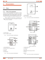
3.1.1. Views of the equipment.
Figures 1 to 4 show the illustrations of the equipment according
to the case format and depending on the power of the model.
Nevertheless and due to the constant evolution of the product,
some discrepancies or small contradictions can arise. In front
of any doubt, the labelling of the equipment will always prevail.
Figures regarding its main features or specifications can
be checked in the nameplate of the equipment. Keep them
in mind for its installation.
1. LCD Back-Light.
2. Power «ON/OFF» Switch.
Fig. 1. Front view from SOHO+ 400/600/800 VA.
1. Communication Port.
2. Modem/Phone Line Surge Protection.
3. AC Output.
4. AC Input.
5. Circuit breaker.
Fig. 2. Rear view from SOHO+ 400/600/800 VA.
1. LCD Back-Light.
2. Power «ON/OFF» Switch.
Fig. 3. Front view from SOHO+ 1000/1400/2000 VA.
SOHO+ 1000 VA
SOHO+ 1400/2000 VA
1. Communication Port.
2. Cooling Fan.
3. AC Output.
4. Modem/Phone Line Surge Protection.
5. AC Input.
6. Breaker.
Fig. 4. Rear view from SOHO+ 1000/1400/2000 VA.

10
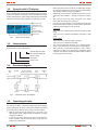
3.2. Synoptic with LCD display.
As it is possible to be observed in the following figure, the equip-
ment has a standart LCD display, where are reflected the input
tension and frequency, output voltage and frequency and the fault
indicators, load level, battery capacity, line and battery modes.
INPUT (Unit: V AC)
LINE MODE (AVR)
OUTPUT (Unit: V AC)
FAULT
BACKUP MODE
BATTERY CAPACITY
LOAD LEVEL
Fig. 5. Synoptic with LCD display
3.3. Nomenclature.
SPS.400.SOHO+ 220V “EE61837-37”
Special equipment “EE”.
Input/Output voltage dif-
ferent to 230V.
SPS series.
Power in VA.
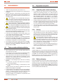
3.4. Structural diagram.
Electronic stabiliser
(Boost-up / Back down)
Relais
Bypass
Inverter
BatteriesCharger
Input filterInput
AC
N
F
N
F
Output
AC
Fig. 6. SPS SOHO+ series block diagram.
3.5. Operating principle.
The SPS is an off-line, interactive Uninterrupted Power Supply
System (electronic Boost-up / Back-down stabiliser),controlled
by microprocessor. With the unit running, it works as follows:
• With the mains present at between 75 % and 125 % the
SPS supplies output voltage through the stabiliser, as wellas
charging the batteries.
• In the event of mains absent or incorrect (off margins) the
inverter supplies pseudo-sinusoidal wave energy from the
batteries for a limited time.
• When the mains returns or finds its corresponding margins,
the charge is supplied once more from the commercial mains
after filtering, and also through the stabiliser.
• Additionally, it has protection against tension tips to the tel-
ephone line (Fax, Modem...), through connectors RJ-11/RJ-
45.
• The mere fact of the unit being connected to the mains
means that the batteries are recharged.
• If the SPS is overloaded in any of its working modes and the
load connected to the output is not reduced, the unit will stop
supplying output voltage in a few seconds:
Line Mode
110%+20%/-10%; shutdown after 5 minutes and pass to fault
mode.
120%+20%/-10%; shutdown immediate and passo to fault
mode.
Battery Mode
110%+20%/-10%; shutdown aflter 5 seconds.
120%+20%/-10%; shutdown immediate.
• The unit has automatic detection of the input frequency,
which is activated when it is connected to the mainssupply.
• With a software of supervision «Winpower» and a cable of
connection in order to use between the equipment and its
computer, an intelligent operation is obtained, that provides a
perfect protection of the loads.
USER MANUAL

11
SALICRU
4. Installation.
• Check the Safety instructions, from section 1.2.3.
• Check that the data in the nameplate are the required by the
installation.
• A wrong connection or manoeuvring, can make faults in the
SPS and/or loads connected to itself. Read carefully the in-
structions of this manual and follow the stated steps in the
established order.
• The equipments can be installed and used by per-
sonnel with no specific training just with the help of this
«Manual» only, less those ones that are hard wired, which
have to be installed by qualified personnel.
• All connections of the equipment including the control (in-
terface, remote panel, ...), will be done with the switches at
rest and no voltage present (SPS power supply switch to «Off»).
• Never forget that the SPS is an electrical energy gener-
ator, so the user has to take the needed cautions against
direct and indirect contacts.
• Connection to any other type of receptacle other than a two-
pole, three-wire grounding receptacle may result in shock
hazard as well as violate local electrical codes.
• In the event of an emergency, turn the power switch to the
«off» position and disconnect the power cord form the AC
power supply to properly disable the SPS.
• This unit intended for installation in a controlled environment
(temperature controlled, indoor area free of conductive con-
taminants). Avoid installing the SPS in locations where there
is standing or running water, or excessive humidity.
• Do not attach a power strip or surge suppressor to the SPS.
• Do not attach non-computer-related items, such as medical
equipment, life-support equipment, microwave ovens, or
vacuum cleaners to SPS.
4.1. To be considered in the installation.
• All the equipments have power cord with schuko plug to be
connected to the AC mains.
In the same way, 2 or 3 schuko outlets are supplied depending
on the model, for its connection with the loads (output).
• Cross cable section of the input and output lines, will be cal-
culated from the currents stated in the nameplate of each
equipment, and respecting the Local and/or National Low
Voltage Electrotechnical Regulations.
• Protections of the switchgear panel, will have the following
features:
For input line, type B for RCD devices and C character-
istic for circuit breakers.
For the output (load feeding), C characteristic for circuit
breaker.
Regarding the size, they will be as minimum to the currents
stated in the nameplate of each SPS.
• In the nameplate of the equipment there are only printed the
nominal currents as it is stated in the safety standard EN-IEC
62040-1. To calculate the input current, the power factor and
the efficiency of the equipment have been considered.
Overload conditions are considered as nonpermanent and
exceptional operating mode.
4.2. Equipment reception.
4.2.1. Unpacking and contents checking.
• On receiving the unit, make sure that it has not been dam-
aged in any way during transport, so it could be better to
unpack it to make a visual inspection and to check that the
features of itself corresponds to those specified in the order
(See nameplate sticked to the packing). If it is damaged,
make all suitable claims to your supplier or, short of this, to
our firm, by mentioning the serial number of the equipment
and the references of the delivery invoice.
• Having completed the reception, it is best to pack the equip-
ment into its original packing until it is put into service in order
to protect it against possible mechanical impacts, dust, dirt,
etc. In any case we recommend to keep the packing.
• The packing is made of recycable materials, therefore if they
are to be disposed, it must be done in accordance with the
effective laws.
4.2.2. Storing.
• The unit must be stored in a dry and well-ventilated place
and protected from the rain, water projections or chemical
agents. It is best to keep the unit in their original packing as
this packing has been specifically designed to ensure max-
imum protection during transport and storage.
• The SPS includes sealed lead-calcium batteries, and
they should not be stored for more than 4 months
without recharging the batteries for 6 hours minimum. This
means that the unit shall be connected to the commercial
mains and started up. Once the batteries are recharged re-
turn the equipment to its original packing.
Do not store the devices where the ambient temperature ex-
ceeds 40º C or falls below -20º C, otherwise it might deterio-
rate the electrical characteristics of the batteries.
4.2.3. Location.
Install the SPS unit in any protected environment that provides
adequate airflow around the unit, and is free from excessive dust,
corrosive fumes and conductive contaminants. Do not operate
your SPS in an environment where the ambient temperature or
humidity is high. On the other hand, place the SPS unit away
from monitor at least 20cm to avoid interference.
4.2.4. Battery charging.
This unit is shipped from the factory with its internal battery fully
charged. however, some energy may be lost during shipping so
the battery should be recharged before using it. Plug the unit into
an appropriate power supply and allow the SPS to charge fully by
leaving it plugged in for 8 hours.(models 400/600/800 VA) and for
10 hours (models 1000/1400/2000 VA).

12
4.3. Communication ports.
4.3.1. Description and features.
New series SOHO+ incorporates a port USB with which to com-
municate with the outside.
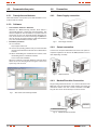
4.3.2. Software.
• Free software download - WinPower.
WinPower is a SPS monitoring software, which makes a
user-friendly interface of monitoring and management. This
software supplies an auto Shutdown for a system based on
several PCs in case of an electrical blackout. With this soft-
ware, the end-users can monitor and manage any SPS in the
same IT network, through the RS232 or USB communication
port, never mind the distance between them.
• Installation procedure:
Go to website:
http://support.salicru.com
Choose the operating platform that you need and follow
the instructions described in the web site to download the
software.
When downloading the needed files from Internet, enter
the following licence to install the software:
511C1-01220-0100-478DF2A .
When the computer is rebooted, WinPower software will be
shown as an icon with plug shape and green colour in the
system tray, near the clock.
Fig. 7. Main screen of the monitoring software.
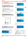
4.4. Connection.
4.4.1. Power Supply connection.
Fig. 8. Power supply connection.
4.4.2. Output connection.
Connect one computer-related device into each of the power re-
ceptacles supplied on the back of the SPS (maximum of two or
three depending on model).
Fig. 9. Output connection.
4.4.3. Modem/Phoneline Connection.
Plug incoming internet line into the «In» socket at the back of the
SPS. Use one more Internet line cable and plug one end of the
Internet line cable to the «Out» socket at the back of the SPS.
Plug the other end to the modem input socket as shown.
Modem / Fax / Phone
Wall Outlet
Fig. 10. Modem/Phoneline Connection.
USER MANUAL

13
SALICRU
5. OPERATION.
5.1. Preliminary controls.
• Make sure that all connections have been done properly, and
respecting the labelling of the equipment and the instructions
of chapter 4.
• Check that the power supply is correct.
• Check that the SPS is Off (shutdown).
• Make sure that all loads are shutdown «Off».
Loads can be connected after the SPS start up and
one by one. Before shutdown the SPS, check that all
loads are shutdown (Off).
• Check that the thermal protection of the equipment is not
tripped.
• Turn “ON” the protection of the distribution panel.
5.2. Start up and shutdown.
To turn on the SPS unit, press the power switch lightly. To turn
off the SPS unit, press the power switch again (When switch ON
the LED lighting.).
Fig. 11. Start up and shutdown.
5.3. LCD display.
The LED will always turns on when SPS works, including in off
charging mode and fault mode.
When LCD start to work, it will display all information for 3s:
INPUT (Unit: V AC)
LINE MODE (AVR)
OUTPUT (Unit: V AC)
FAULT
BACKUP MODE
BATTERY CAPACITY
LOAD LEVEL
Fig. 12. LCD display.
• When in normal mode, it will display as below.
Fig. 13. Screen normal mode.
• When in AVR mode, it will display as below. And the mark
will flicker every 1 second.
Fig. 14. Screen AVR mode.
• When in battery mode, il will display as below. And the
mark will flicker every 1 second.
Fig. 15. Screen battery mode.
Note: If I/P-V < 40 V, input voltage will display “000”.
• When in off charging mode, it will display as below.
Fig. 16. Screen charging mode.
Note: The output voltage always is displayed as “000” in off
charging mode.
• When in fault mode, it will display as below.
Fig. 17. Screen fault mode.
• Load level definition:
Load level Battery bar indication
0.. 25 %
25.. 50 %
50.. 75 %
75.. 100 %
Table 1. Load level.

14
• Battery capacity definition:
Battery bar indication
Battery voltage ≤ 11 V
11 V ≤ Battery voltage ≤ 11,5 V
11,5 V ≤ Battery voltage ≤ 12,5 V
Battery voltagea ≥ 12,5 V
Battery level
Table 2. Battery level.
• When over load, the mark will flicker every 1 second.
• When battery low, the mark will flicker every 1 second.
USER MANUAL

15
SALICRU
6. Maintenance, w arran ty and
service.
6.1. Basic maintenance guide.
The main guidelines for a correct maintenance are similar to the
ones that are applying our Service and Technical Support in the
Preventive maintenance modality (see section 6.5).
6.2. Battery maintenance.
• Pay attention to the safety instructions regarding battery and
the stated in section 1.2.3.3.
• The SPS from SOHO+ series only requires a minimum main-
tenance. The used battery in the standard models is lead
acid, sealed, VRLA and maintenance free. These models
require a minimum of reparations. The only requirement
is to charge the SPS regularly, in order to prolong the bat-
tery lifetime. Meanwhile, it is connected to the power supply,
never mind if the SPS is ON or OFF, it will keep the batteries
charged and will give protection against overcharging and
undercharging.
• The SPS has to be charged once, every 4 or 6 months if it
has not been used for long time.
• In hot areas, battery has to be charged every 2 months. The
charging time has to be 12 hours as minimum.
• Under normal conditions, the battery lifetime is from 3 to 5
years 25º C. In case that the battery was not in good condi-
tions, it has to be replaced before. This replacement has to
be done by qualified staff.
• Always replace them with the same quantity and type.
• Do not replace one battery only. All batteries have to be re-
placed at the same time and following the instructions of the
manufacturer.
• Usually, the batteries should be charged and discharged
every 4 or 6 months. The charging would be started after shut-
down the SPS due to a low battery (discharging). Charging
time for standard SPS should be 12 hours as minimum.
6.2.1. Notes for installing and replacing the
batteries.
• If it is needed to replace the connection of any wire, purchase
original parts through authorised distributors or service cen-
tres in order to avoid overheating and sparks with fire risk
because the size is not enough.
• Do not short the + and - poles of the batteries, there is risk of
fire or electrocution.
• Be sure that there is no voltage before touching the batteries.
Battery circuit is not isolated from the input. Hazardous volt-
ages can be found between the battery and earth terminals
• Although the input circuit breaker the switchgear panel is
turned off, the internal parts of the SPS are still connected to
the batteries, so there are hazardous voltages inside.
Therefore, before doing any reparation or maintenance task,
the internal battery fuses have to be removed and/or the in-
terlink connections between them and the SPS.
• Batteries have hazardous voltages. The battery maintenance
and replacement have to be done by qualified personnel and
familiarised with them. Nobody else can manipulate them.
6.3. SPS troubleshooting guide.
If the SPS doesn’t work properly, check the information given by
the LCD of the control panel. Try to solve the problem by means
of the established steps in the table 3. In case the problem per-
sists, consult with our Service and Technical Support S.T.S..
When it is needed to contact with our Service and Technical Sup-
port S.T.S. , provide the following information:
• SPS model and serial number.
• Date when the problem occurred.
• Complete description of the problem, including the informa-
tion given by the LCD panel and the status of the alarms.
• Power supply condition, type of load and the level connected
to the SPS, ambient temperature, cooling conditions.
• Other informations that you may think that they are important.
Symptom Possible Cause Remedy
LCD display is not
illuminated
1. Unloaded battery.
1. Charge battery up to
8 hours.
2. Battery defect.
2. Replace with the
same type of battery.
3.When the Input cord
isn’t electrified and
Power switch is not
pressed.
3. Press the power
switch again or test the
Input cord.
Alarm buzzer beeps
continuously when AC
supply is normal.
Overload of the UPS.
Verify that the load
matches the UPS
capability specified in
the specs.
When power failure,
back-up time is
shorten.
1. Overload of the UPS.
1. Remove some
noncritical load.
2. Battery voltage is
too low.
2. Charge battery 8
hours or more.
3. Battery defect due
to high temperature
operation environment,
or improper operation to
battery.
3. Replace with the
same type of battery.
Communication lost
between UPS and
computer.
1. Software is not
installed well.
1. Check the setting of
the software .
2. Cable is not properly
connected.
2. Check the USB cable
is firmly connected
to the computer and
confirm the setting
again.
Mains normal but LCD
display Battery mode.
1. Circuit breaker
tripped.
1. Reset the circuit
breaker.
2. Power cord is loose.
2. Reconnect the power
cord properly.
Table 3. SPS troubleshooting guide.
6.4. Warranty conditions.
The limited warranty only applies to those products that you ac-
quire for commercial or industrial use in the normal development
of your business.

16
6.4.1. Covered product.
SPS SOHO+ series.
6.4.2. Warranty terms.
See product conditions as in Website.
6.4.3. Out of scope of supply.
Our company is not forced by the warranty if it appreciates
that the defect in the product doesn’t exist or it was caused by
a wrong use, negligence, installation and/or inadequate testing,
tentative of repairing or not authorized modification, or any other
cause beyond the foreseen use, or by accident, fire, lightnings or
other dangers. Neither it will cover, in any case, compensations
for damages or injuries.
6.5. Technical service network.
Coverage, both national and international, from our Service and
Technical Support (S.T.S.), can be found in our Website.
USER MANUAL

17
SALICRU
7. Annexes.
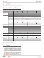
7.1. General technical specifications.
MODEL SPS.400.SOHO+ SPS.600.SOHO+ SPS.800.SOHO+ SPS.1000.SOHO+ SPS.1400.SOHO+ SPS.2000.SOHO+
CAPACITY VA / W 400 / 240 600 / 360 800 / 480 1000 / 600 1400 / 840 2000 / 1200
INPUT
Voltage 220, 230, 240 VAC 230, 240 VAC
Voltage Range 162-290 VAC 166-290 VAC
Frequency 50 Hz / 60 Hz
OUTPUT
Voltage 220, 230, 240 VAC 230, 240 VAC
Voltage regulation
(Battery Mode)
± 10 % ± 5 % at load < 50 %
Frequency 50 Hz / 60 Hz
Frequency regulation
(Battery Mode)
± 1 Hz
Output Waveform Pseudo Sine-wave
BATTERY
Battery Type and No 12 V / 4.5 Ah x 1pcs 12 V / 28 W x 1 pcs 12 V / 34 W x 1 pcs 12 V / 7 Ah x 2 pcs 12 V / 9 Ah x 2 pcs
Back up Time
(1)
8 minutes 10 minutes 6 minutes
Recharge Time 8 Hours to 90 % after complete discharge 10 Hours to 90 % 6 Hours to 90%
TRANSFER TIME Typical 2 - 6 ms 4 - 6 ms 4 - 8 ms
INDICATOR LCD Display The LCD will always turn on when UPS work, including in off charging mode and fault mode
AUDIBLE ALARM
Battery Mode Sounding every 10 seconds
Battery Low Sounding every 1 second
Overload Sounding every 0,5 seconds
Battery replace Sounding every 2 seconds
Fault Continuously sounding
Buck / Boost with > 70
% SPS load
Sounding every 0.5 seconds after 25 min. and fault after 30
min.
NA
PROTECTION Full protection Discharge, Overcharge, Short Circuit and Overload Protection
PHYSICAL
Dimension (DxWxD)
(mm.)
330 x 100 x 140 399 x 145 x 205
Net Weight (Kg.) 4.5 5 6.5 9 9.5 10
ENVIRONMENT
Operating 0 - 40 ºC, 0 - 90 % Relative Humidity (non-condensing)
Noise Level Less than 40 dB Less than 45 dB
INTERFACE USB For Windows family & MAC
(1) Minimum at 50% load.
Table 4. General technical specifications.
7.2 . Glossary.
• Electromagnetic Compatibility.- Branch of the electronic
and telecommunication technology that is in charge of the in-
terferences between the electric and electronic equipments.
It is defined (in accordance with the international standard
collected on the Technical file of the International Electro-
technical Comission 61000-1-1) as «the capacity of any de-
vice, equipment or system to operate in suitable way in its
electromagnetic environment without making electromag-
netic perturbations over anything in that environment».
• VA.- Voltampere is the unit of the apparent power in alter-

18
nating current. In the direct current is almost equal to the real
power but in the alternating current it can be different de-
pending on the power factor. The voltamperes are arithmetic
product of the multiplication between the voltage and current.
• LCD.- LCD are the English acronyms of Liquid Crystal Dis-
play.
• Serial port.- A serial port is a communication interface among
computers and peripherals, where the data is transmitted bit
by bit and sending one bit only every time, meanwhile the
parallel port sends several bits at the same time.
• Modem.- It is the acronym of the words modulator/demodu-
lator. Modulador sends a constant analogical signal called
holder. Generally, it is a simple sinewave. When digital data
needs to be sent, it is modified any characteristic of the holder
signal, therefore it is stating if it is sending a «zero» or «one».
• Circuit breaker.- A circuit breaker is based in the operation
of two effects made by the electrical current circulation in a
circuit, the magnetic and thermal (Joule effect). So, the de-
vice has two parts, an electromagnetic and a b i -
metal plate, connected in series and the current is circulating
through them to the load.
• LAN.- LAN is the acronym of Local Area Network or just
Local Network. A local network interconnects several com-
puters and peripherals. Its extension is physically limited to
one building or to one surrounding of a few kilometers. Its
most extended application is the interconnection of personal
computers and workstations in offices, factories, etc; to share
resources and to exchange data and applications.
• AVR.- It is the acronym of Automatic Voltage Regulator, and
it is a device ready to stabilize the output electrical voltage
to preset values (accuracy) in front of fluctuations at its input
(input range).
• Autonomy.- It is the time, previously specified, during which
the SPS is able to supply a fixed voltage and frequency and a
certain current to the loads connected to is output.
• Transfer time.- It is the time that lapses in a Line Interactive
or Off-Line SPS when the input mains faults and the inverter
starts up and supplies output voltage. Usually it is around a
few miliseconds.
USER MANUAL

19
SALICRU
: ....................................................................................................................................................................................................................
................................................................................................................................................................................................................................
................................................................................................................................................................................................................................
................................................................................................................................................................................................................................
................................................................................................................................................................................................................................
................................................................................................................................................................................................................................
................................................................................................................................................................................................................................
................................................................................................................................................................................................................................
................................................................................................................................................................................................................................
................................................................................................................................................................................................................................
................................................................................................................................................................................................................................
................................................................................................................................................................................................................................
................................................................................................................................................................................................................................
................................................................................................................................................................................................................................
................................................................................................................................................................................................................................
................................................................................................................................................................................................................................
................................................................................................................................................................................................................................
................................................................................................................................................................................................................................
................................................................................................................................................................................................................................
................................................................................................................................................................................................................................
................................................................................................................................................................................................................................
................................................................................................................................................................................................................................
................................................................................................................................................................................................................................
................................................................................................................................................................................................................................
................................................................................................................................................................................................................................
................................................................................................................................................................................................................................

UNINTERRUPTIBLE POWER SUPPLY (UPS) + LIGHTING FLOW DIMMER STABILIZERS (ILUEST) + SWITCH MODE POWER SUPPLY + STATIC INVERTERS + PHOTOVOLTAIC INVERTERS + VOLTAGE STABILIZERS AND POWER LINE CONDITIONERS
Avda. de la Serra, 100
08460 Palautordera
BARCELONA
Tel. +34 93 848 24 00
902 48 24 00 (Only Spain)
Fax. +34 94 848 11 51
salicru@salicru.com
Tel. (S.T.S.) +34 93 848 24 00
902 48 24 01 (Only Spain)
Fax. (S.T.S.) +34 93 848 22 05
sst@salicru.com
SALICRU.COM
BARCELONA
BILBAO
GIJÓN
LA CORUÑA
LAS PALMAS DE G. CANARIA
MADRID
MÁLAGA
MURCIA
PALMA DE MALLORCA
PAMPLONA
SAN SEBASTIÁN
SEVILLA
VALENCIA
VALLADOLID
ZARAGOZA
BRANCHES AND SERVICES AND TECHNICAL
SUPPORT (S.T.S.)
CHINA
FRANCIA
HUNGRÍA
MARRUECOS
MÉXICO
PORTUGAL
REINO UNIDO
SINGAPUR
SUBSIDIARIES
ALEMANIA
ARABIA SAUDÍ
ARGELIA
ARGENTINA
BÉLGICA
BRASIL
CHILE
COLOMBIA
CUBA
DINAMARCA
ECUADOR
EGIPTO
FILIPINAS
HOLANDA
INDONESIA
IRLANDA
JORDANIA
KUWAIT
MALASIA
PERÚ
POLONIA
REPÚBLICA CHECA
RUSIA
SUECIA
SUIZA
TAILANDIA
TÚNEZ
UEA
URUGUAY
VENEZUELA
VIETNAM
REST OF WORLD
Product Range
Uninterruptible Power Supply (UPS)
Lighting Flow Dimmer-Stabilizers (ILUEST)
Switch Mode Power Supplies
Static Inverters
Photovoltaic Inverters
Voltage Stabilisers and Power Line Conditioners
Nota: Salicrú can give other electronics solutions according to the application specifications or technical specifications.
EK976A01
-
 1
1
-
 2
2
-
 3
3
-
 4
4
-
 5
5
-
 6
6
-
 7
7
-
 8
8
-
 9
9
-
 10
10
-
 11
11
-
 12
12
-
 13
13
-
 14
14
-
 15
15
-
 16
16
-
 17
17
-
 18
18
-
 19
19
-
 20
20


Salicru SPS.1000.SOHO+ User manual
- Type
- User manual
- This manual is also suitable for
Ask a question and I''ll find the answer in the document
Finding information in a document is now easier with AI
Related papers
-
Salicru SLC-8000 TWIN PRO User manual
-
 Salicru Soho series User manual
-
 Salicru SPS.2000.SOHO Leaflet
-
Salicru SLC-700-TWIN RT (B1) User manual
-
 Salicru SPS.600.SOHO User manual
-
 Salicru SPS.1500.ADV RT (B0) User manual
-
 Salicru SPS.HOME User manual
-
 Salicru SPS.400.HOME User manual
-
 Salicru SLC-3000-TWIN PRO User manual
-
 Salicru SLC-700 TWIN PRO (B1) User manual


Other documents
-
 PowerWalker VFI 60K CPT 3/3 BX Owner's manual
-
BlueWalker PowerWalker VI 2000RT LCD User manual
-
Digitus DN-170110 Quick start guide
-
Mustek 98-0CD-PR140 Datasheet
-
-
AEG PROTECT A User manual
-
AEG Protect alpha 450 User manual
-
-
Omron BU3002SW User manual
-
