Generac 16 kW G0071411 User manual

Category
Power generators
Type
User manual
Installation Guidelines
60 Hz Air-Cooled Generators
16 kW and 22 kW
SAVE THIS MANUAL FOR FUTURE REFERENCE
Para español, visita: http://www.generac.com/service-support/product-support-lookup
Pour le français, visiter : http://www.generac.com/service-support/product-support-lookup
®
Register your Generac product at:
WWW.ACTIVATEGEN.COM
(000209b)
WARNING
Loss of life. This product is not intended to
be used in a critical life support application.
Failure to adhere to this warning could result
in death or serious injury.
ii Installation Guidelines for 60 Hz Air-Cooled Generators
Use this page to record important information about this generator.
Record the information found on the unit data label on this
page. For the location of unit data label, see owner’s man-
ual. The unit has a label plate affixed to the inside partition,
to the left of the control panel console.
Always supply the complete model and serial numbers of the
unit when contacting an Independent Authorized Service
Dealer (IASD) about parts and service.
Operation and Maintenance: Correct maintenance and
care of the generator ensures a minimum number of prob-
lems, and keeps operating expenses at a minimum. It is the
operator’s responsibility to perform all safety checks, to ver-
ify all maintenance for safe operation is performed promptly,
and to have the equipment inspected periodically by an
IASD. Normal maintenance, service, and replacement of
parts are the responsibility of the owner/operator and are not
considered defects in materials or workmanship within the
terms of the warranty. Individual operating habits and usage
may contribute to the need for additional maintenance or ser-
vice.
When the generator requires servicing or repairs, Generac
recommends contacting an IASD for assistance. Authorized
service technicians are factory-trained and are capable of
handling all service needs. To locate the nearest IASD,
please visit the dealer locator at:
www.generac.com/Service/DealerLocator/.
Model:
Serial:
Prod Date:
Volts:
LPV Amps:
NG Amps:
Hz:
Phase:
Controller P/N:
(000393a)
WARNING
CANCER AND REPRODUCTIVE HARM
www.P65Warnings.ca.gov.
Installation Guidelines for 60 Hz Air-Cooled Generators iii
Section 1: Safety Rules & General
Information
Introduction ..........................................................1
Read This Manual Thoroughly ....................................1
Safety Rules .........................................................1
How to Obtain Service .................................................1
General Hazards ..................................................2
Exhaust Hazards ..................................................3
Electrical Hazards ................................................3
Fire Hazards .........................................................3
Explosion Hazards ...............................................4
Battery Hazards ...................................................4
General Rules .......................................................5
Before You Begin ........................................................5
NEC Requirements ......................................................5
Standards Index ..........................................................5
Section 2: Unpacking and Inspection
General .................................................................7
Required Tools .....................................................7
Unpacking ............................................................7
Opening the Lid ...........................................................8
Enclosure Panel Removal ...................................8
Front Access Panel Removal ......................................8
Intake Side Panel Removal .........................................9
Customer Connections and Loose Parts ..........9
Rear Connections ................................................9
Generator Main Line Circuit Breaker ...............10
Parts Shipped Loose .........................................10
Auxiliary Shutdown Switch ...............................10
Section 3: Site Selection and Preparation
Site Selection .....................................................11
Carbon Monoxide ..............................................11
Carbon Monoxide Detectors ......................................11
Potential CO Entry Points ..........................................12
Protect the Structure .................................................12
Fire Prevention ...................................................13
Distance Requirements .............................................13
Fire Codes, Standards, and Guidelines .....................14
Generator Maintenance .............................................14
Fresh Air for Ventilation and Cooling ..............15
Water Ingress Avoidance .................................. 15
Proximity to Utilities ..........................................15
Verify Wi-Fi Range ....................................................15
Transportation Recommendations .................. 15
Suitable Mounting Surface ............................... 15
Placement on Roofs, Platforms, and Other
Supporting Structures ......................................15
Section 4: Generator Placement
Generator Placement ........................................17
Fascia Installation (If Applicable) ..................... 17
Section 5: Fuel Conversion / Fuel
Connections
Fuel Requirements and Recommendations ....19
BTU Content ..............................................................19
Fuel Pressure ............................................................19
Fuel Conversion ................................................19
Fuel Consumption ............................................. 20
Fuel Line Sizing .................................................20
Natural Gas Pipe Sizing ............................................21
LP Vapor Pipe Sizing ................................................21
Installing and Connecting Fuel Lines ..............22
Fuel Shutoff Valve .....................................................22
Flexible Fuel Line ......................................................22
Sediment Trap ...........................................................22
Checking Fuel Line Connections .....................23
Checking Fuel Pressure ............................................23
Performing Fuel System Leak Test ...........................23
Natural Gas Installation (Typical) ..................... 24
LP Gas (Vapor) Installation (Typical) ...............25
Section 6: Electrical Connections
Generator Connections ..................................... 27
Control Wiring .................................................... 28
Main AC Wiring ..................................................29
Service Entrance Decals ...................................29
Common Alarm Relay (Option) ........................ 29
Battery Requirements ....................................... 29
Battery Installation ............................................30
Connecting Battery ....................................................30
Battery Disposal ................................................30
Table of Contents
Table of Contents
iv Installation Guidelines for 60 Hz Air-Cooled Generators
Section 7: Control Panel Startup/Testing
Control Panel Interface .....................................31
Using the AUTO/MANUAL/OFF Buttons ................. 31
Generator Setup .................................................31
Activation .................................................................. 31
Cold Smart Start ....................................................... 33
Setting The Exercise Timer ....................................... 33
Before Initial Startup .........................................33
Install Wizard ............................................................ 34
Interconnect System Self Test Feature ..................... 34
Before starting, complete the following: .................... 34
Checking Manual Transfer Switch
Operation ............................................................37
Electrical Checks ...............................................37
Generator Tests Under Load ............................37
Checking Automatic Operation ........................38
Installation Summary ........................................38
Shutting Generator Down While Under
Load or During a Utility Outage ........................38
Section 8: Troubleshooting
Section 9: Quick Reference Guide
System Diagnosis ..............................................43
Section 10: Accessories
Accessories ........................................................45
Section 11: Diagrams
Installation Drawing (10000010258 rev B—1 of 2) ... 47
Installation Drawing (10000010258 rev B—2 of 2 .... 48
Safety Rules & General Information
Installation Guidelines for 60 Hz Air-Cooled Generators 1
Section 1: Safety Rules & General Information
Introduction
Thank you for purchasing this compact, high perfor-
mance, air-cooled, engine-driven generator. It is design-
ed to automatically supply electrical power to operate
critical loads during a utility power failure.
This unit is factory installed in an all-weather, metal
enclosure that is intended exclusively for outdoor installa-
tion. This generator will operate using either vapor with-
drawn liquid propane (LP) or natural gas (NG).
NOTE: When sized correctly, this generator is suitable
for supplying typical residential loads such as induction
motors (sump pumps, refrigerators, air conditioners, fur-
naces, etc.), electronic components (computer, monitor,
TV, etc.), lighting loads, and microwaves. This unit is also
equipped with a Wi-Fi
®
module, which enables the gen-
erator owner to monitor generator status from anywhere
they have Internet access.
NOTE: Wi-Fi
®
is a registered trademark of Wi-Fi Alli-
ance
®
.
The information in this manual is accurate based on
products produced at the time of publication. The manu-
facturer reserves the right to make technical updates,
corrections, and product revisions at any time without
notice.
Read This Manual Thoroughly
If any section of this manual is not understood, contact
the nearest Independent Authorized Service Dealer
(IASD) or Generac Customer Service at 1-888-436-3722
(1-888-GENERAC), or visit www.generac.com for start-
ing, operating, and servicing procedures. The owner is
responsible for correct maintenance and safe use of the
unit.
This manual must be used in conjunction with all other
supporting product documentation supplied with the
product.
SAVE THESE INSTRUCTIONS for future reference. This
manual contains important instructions that must be fol-
lowed during placement, operation, and maintenance of
the unit and its components. Always supply this manual
to any individual that will use this unit.
Safety Rules
The manufacturer cannot anticipate every possible cir-
cumstance that might involve a hazard. The alerts in this
manual, and on tags and decals affixed to the unit, are
not all inclusive. If using a procedure, work method, or
operating technique that the manufacturer does not spe-
cifically recommend, verify that it is safe for others and
does not render the equipment unsafe.
Throughout this publication, and on tags and decals
affixed to the unit, DANGER, WARNING, CAUTION, and
NOTE blocks are used to alert personnel to special
instructions about a particular operation that may be haz-
ardous if performed incorrectly or carelessly. Observe
them carefully. Alert definitions are as follows:
NOTE: Notes contain additional information important to
a procedure and will be found within the regular text of
this manual.
These safety alerts cannot eliminate the hazards that
they indicate. Common sense and strict compliance with
the special instructions while performing the action or
service are essential to preventing accidents.
How to Obtain Service
When the unit requires servicing or repairs, contact Gen-
erac Customer Service at 1-888-GENERAC (1-888-436-
3722) or visit www.generac.com for assistance.
When contacting Generac Customer Service about parts
and service, always supply the complete model and
serial number of the unit as given on its data decal
located on the unit. Record the model and serial numbers
in the spaces provided on the front cover of this manual.
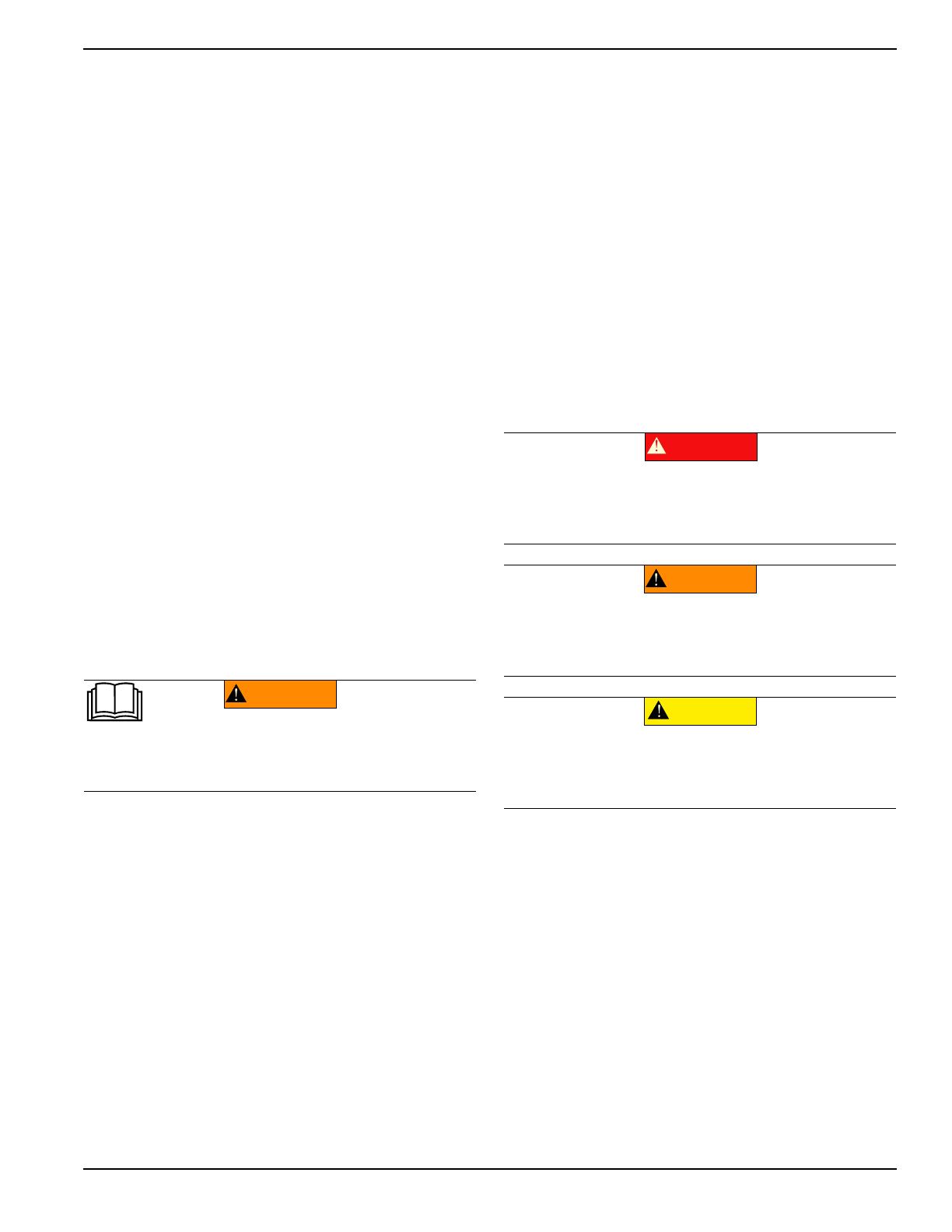
(000100a)
WARNING
Consult Manual. Read and understand manual
completely before using product. Failure to
completely understand manual and product
could result in death or serious injury.
(000001)
DANGER
Indicates a hazardous situation which, if not avoided,
will result in death or serious injury.
(000002)
WARNING
Indicates a hazardous situation which, if not avoided,
could result in death or serious injury.
(000003)
CAUTION
Indicates a hazardous situation which, if not avoided,
could result in minor or moderate injury.
Safety Rules & General Information
2 Installation Guidelines for 60 Hz Air-Cooled Generators
General Hazards
Inspect the generator regularly, and contact the
nearest IASD for parts needing repair or replace-
ment.
(000190)
DANGER
Loss of life. Property damage. Installation must always
comply with applicable codes, standards, laws and
regulations. Failure to do so will result in death
or serious injury.
Automatic start-up. Disconnect utility power and
render unit inoperable before working on unit.
Failure to do so will result in death or serious injury.
(000191)
DANGER
(000187)
WARNING
Electrocution. Potentially lethal voltages are generated
by this equipment. Render the equipment safe before
attempting repairs or maintenance. Failure to do so
could result in death or serious injury.
(000209b)
WARNING
Loss of life. This product is not intended to
be used in a critical life support application.
Failure to adhere to this warning could result
in death or serious injury.
(000130)
WARNING
Accidental Start-up. Disconnect the negative battery
cable, then the positive battery cable when working
on unit. Failure to do so could result in death
or serious injury.
(000182a)
WARNING
Equipment damage. Only qualified service personnel may
install, operate, and maintain this equipment. Failure to follow
proper installation requirements could result in death, serious
injury, and equipment or property damage.
WARNING
Equipment damage. This unit is not intended for use as a
prime power source. It is intended for use as an intermediate
power supply in the event of temporary power outage only.
Doing so could result in death, serious injury, and
equipment damage.
(000247a)
(000155a)
WARNING
Electric shock. Only a trained and licensed electrician
should perform wiring and connections to unit. Failure
to follow proper installation requirements could result in
death, serious injury, and equipment or property damage.
(000115)
WARNING
Moving Parts. Do not wear jewelry when
starting or operating this product. Wearing
jewelry while starting or operating this product
could result in death or serious injury.
(000111)
WARNING
Moving Parts. Keep clothing, hair, and
appendages away from moving parts. Failure
to do so could result in death or serious injury.
(000108)
WARNING
Hot Surfaces. When operating machine, do not
touch hot surfaces. Keep machine away from
combustibles during use. Hot surfaces could
result in severe burns or fire.
(000146)
WARNING
Equipment and property damage. Do not alter
construction of, installation, or block ventilation for
generator. Failure to do so could result in unsafe
operation or damage to the generator.
WARNING
Risk of injury. Do not operate or service this machine
if not fully alert. Fatigue can impair the ability to service
this equipment and could result in death or serious
injury.
(000215)
WARNING
Environmental Hazard. Always recycle batteries at an
official recycling center in accordance with all local
laws and regulations. Failure to do so could result in
environmental damage, death or serious injury.
(000228)
WARNING
Injury and equipment damage. Do not use generator
as a step. Doing so could result in falling, damaged
parts, unsafe equipment operation, and could result
in death or serious injury.
(000216)
Safety Rules & General Information
Installation Guidelines for 60 Hz Air-Cooled Generators 3
Exhaust Hazards
The generator must be installed and operated out-
doors only.
Electrical Hazards
Fire Hazards
Asphyxiation. Running engines produce
carbon monoxide, a colorless, odorless,
poisonous gas. Carbon monoxide, if not
avoided, will result in death or serious injury.
(000103)
DANGER
(000146)
WARNING
Equipment and property damage. Do not alter
construction of, installation, or block ventilation for
generator. Failure to do so could result in unsafe
operation or damage to the generator.
(000178a)
Asphyxiation. Always use a battery operated carbon
monoxide alarm indoors and installed according to
the manufacturers instructions. Failure to do so
could result in death or serious injury.
WARNING
(000144)
DANGER
Electrocution. Contact with bare wires,
terminals, and connections while generator
is running will result in death or serious injury.
(000150)
DANGER
Electrocution. Never connect this unit to the electrical
system of any building unless a licensed electrician
has installed an approved transfer switch. Failure to
do so will result in death or serious injury.
(000237)
DANGER
Electrical backfeed. Use only approved switchgear to
isolate generator from the normal power source.
Failure to do so will result in death, serious injury,
and equipment damage.
(000152)
DANGER
Electrocution. Verify electrical system is
properly grounded before applying power.
Failure to do so will result in death or serious
injury.
(000188)
DANGER
Electrocution. Do not wear jewelry while
working on this equipment. Doing so will
result in death or serious injury.
(000104)
DANGER
Electrocution. Water contact with a power
source, if not avoided, will result in death
or serious injury.
(000145)
DANGER
Electrocution. In the event of electrical accident,
immediately shut power OFF. Use non-conductive
implements to free victim from live conductor. Apply
first aid and get medical help. Failure to do so will
result in death or serious injury.
WARNING
Fire hazard. Do not obstruct cooling and
ventilating airflow around the generator. Inadequate
ventilation could result in fire hazard, possible
equipment damage, death or serious injury.
(000217)
WARNING
Fire and explosion. Installation must comply
with all local, state, and national electrical
(000218)
building codes. Noncompliance could result in unsafe
operation, equipment damage, death or serious injury.
WARNING
Fire hazard. Use only fully-charged fire
(000219)
extinguishers rated “ABC” by the NFPA. Discharged or
improperly rated fire extinguishers will not extinguish
electrical fires in automatic standby generators.
WARNING
to use required safety equipment could result
in death or serious injury.
(000257)
Electrocution. Refer to local codes and
standards for safety equipment required when
working with a live electrical system. Failure
Safety Rules & General Information
4 Installation Guidelines for 60 Hz Air-Cooled Generators
Comply with regulations the Occupational Safety and
Health Administration (OSHA) has established, or with
equivalent standards. Also, verify that the unit is applied,
used, and maintained in accordance with the manufac-
turer's instructions and recommendations. Do nothing
that might alter safe application/usage and render the
unit in noncompliance with the aforementioned codes,
standards, laws, and regulations.
Explosion Hazards
Battery Hazards
Always recycle batteries in accordance with local laws
and regulations. Contact your local solid waste collection
site or recycling facility to obtain information on local
recycling processes. For more information on battery
recycling, visit the Battery Council International website
at: http://batterycouncil.org
WARNING
Fire hazard. Use only fully-charged fire
(000252)
extinguishers rated according to applicable industry
standards. Improperly rated fire extinguishers will not
extinguish electrical fires in standby generators.
(000147)
WARNING
Risk of Fire. Unit must be positioned in a
manner that prevents combustible material
accumulation underneath. Failure to do so
could result in death or serious injury.
(000192)
DANGER
Explosion and fire. Fuel and vapors are extremely
flammable and explosive. No leakage of fuel is
permitted. Keep fire and spark away. Failure to do
so will result in death or serious injury.
(000151a)
DANGER
Explosion and fire. Connection of fuel source must be
completed by a qualified professional technician or
contractor. Incorrect installation of this unit will result in
death, serious injury, and property and equipment damage.
(000174)
DANGER
Risk of fire. Allow fuel spills to completely dry
before starting engine. Failure to do so will
result in death or serious injury.
(000110)
WARNING
Risk of Fire. Hot surfaces could ignite
combustibles, resulting in fire. Fire could
result in death or serious injury.
(000188)
DANGER
Electrocution. Do not wear jewelry while
working on this equipment. Doing so will
result in death or serious injury.
(000162)
WARNING
Explosion. Do not dispose of batteries in a fire. Batteries
are explosive. Electrolyte solution can cause burns and
blindness. If electrolyte contacts skin or eyes, flush with water
and seek immediate medical attention.
(000137a)
WARNING
Explosion. Batteries emit explosive gases while charging.
Keep fire and spark away. Wear protective gear when
working with batteries. Failure to do so could result in
death or serious injury.
(000164)
WARNING
Electrical shock. Disconnect battery ground
terminal before working on battery or battery
wires. Failure to do so could result in death
or serious injury.
(000138a)
WARNING
Risk of burns. Batteries contain sulfuric acid and
can cause severe chemical burns. Wear protective
gear when working with batteries. Failure to do
so could result in death or serious injury.
(000163a)
WARNING
Risk of burn. Do not open or mutilate batteries.
Batteries contain electrolyte solution which can
cause burns and blindness. If electrolyte contacts
skin or eyes, flush with water and seek immediate
medical attention.
WARNING
Environmental Hazard. Always recycle batteries at an
official recycling center in accordance with all local
laws and regulations. Failure to do so could result in
environmental damage, death or serious injury.
(000228)
Safety Rules & General Information
Installation Guidelines for 60 Hz Air-Cooled Generators 5
General Rules
Follow all safety precautions in the owner’s man-
ual, installation guidelines manual, and other docu-
ments included with the equipment.
Never energize a new system without opening all
disconnects and breakers.
Always consult local code for additional require-
ments for where unit is being installed.
Incorrect installation can result in personal injury
and damage to the unit. It may also result in the
warranty being suspended or voided. All instruc-
tions listed below must be followed including loca-
tion clearances and pipe sizes.
Before You Begin
Contact local inspector or city hall to be aware of all
federal, state, and local codes which could impact
installation. Secure all required permits before
installing.
Fully comply with all relevant NEC, NFPA, and
OSHA standards, as well as all federal, state, and
local building and electric codes. This unit must be
installed in accordance with current NFPA 37 and
NFPA 70 standards, and any other federal, state,
and local codes for minimum distances from other
structures.
Verify capacity of NG meter or LP tank in regards
to providing sufficient fuel for both the unit and
other household and operating appliances.
NEC Requirements
Local code enforcement may require Arc Fault Circuit
Interrupters (AFCIs) to be incorporated into the transfer
switch distribution panel. The transfer switch provided
with this generator has a distribution panel which will
accept AFCIs (pre-wired transfer switches only).
Siemens Part No. Q115AF - 15A or Q120AF - 20A can
be obtained from a local electrical wholesaler and will
simply replace any of the single pole circuit breakers sup-
plied in the pre-wired transfer switch distribution panel.
Standards Index
Strictly comply with all applicable national, state, and
local laws, as well as codes or regulations pertaining to
the installation of this engine-generator power system.
Use the most current version of applicable codes or stan-
dards relevant to the local jurisdiction, generator used,
and installation site.
NOTE: Not all codes apply to all products and this list is
not all-inclusive. In the absence of pertinent local laws
and standards, the following publications may be used as
a guide (these apply to localities which recognize NFPA
and IBC).
1. National Fire Protection Association (NFPA) 70:
The NATIONAL ELECTRIC CODE (NEC) *
2. NFPA 10: Standard for Portable Fire Extinguishers
*
3. NFPA 30: Flammable and Combustible Liquids
Code *
4. NFPA 37: Standard for Stationary Combustion
Engines and Gas Turbines *
5. NFPA 54: National Fuel Gas Code *
6. NFPA 58: Standard for Storage and Handling Of
Liquefied Petroleum Gases *
7. NFPA 68: Standard On Explosion Protection By
Deflagration Venting *
(000190)
DANGER
Loss of life. Property damage. Installation must always
comply with applicable codes, standards, laws and
regulations. Failure to do so will result in death
or serious injury.
(000237)
DANGER
Electrical backfeed. Use only approved switchgear to
isolate generator from the normal power source.
Failure to do so will result in death, serious injury,
and equipment damage.
(000182a)
WARNING
Equipment damage. Only qualified service personnel may
install, operate, and maintain this equipment. Failure to follow
proper installation requirements could result in death, serious
injury, and equipment or property damage.
WARNING
to use required safety equipment could result
in death or serious injury.
(000257)
Electrocution. Refer to local codes and
standards for safety equipment required when
working with a live electrical system. Failure
(000100a)
WARNING
Consult Manual. Read and understand manual
completely before using product. Failure to
completely understand manual and product
could result in death or serious injury.
(000209b)
WARNING
Loss of life. This product is not intended to
be used in a critical life support application.
Failure to adhere to this warning could result
in death or serious injury.
Safety Rules & General Information
6 Installation Guidelines for 60 Hz Air-Cooled Generators
8. NFPA 70E: Standard For Electrical Safety In The
Workplace *
9. NFPA 110: Standard for Emergency and Standby
Power Systems *
10. NFPA 211: Standard for Chimneys, Fireplaces,
Vents, and Solid Fuel Burning Appliances *
11. NFPA 220: Standard on Types of Building
Construction *
12. NFPA 5000: Building Code *
13. International Building Code **
14. Agricultural Wiring Handbook ***
15. Article X, NATIONAL BUILDING CODE
16. ASAE EP-364.2 Installation and Maintenance of
Farm Standby Electric Power ****
17. ICC:IFGC
This list is not all-inclusive. Check with the Authority Hav-
ing Local Jurisdiction (AHJ) for any local codes or stan-
dards which may be applicable to your jurisdiction. The
above listed standards are available from the following
internet sources:
* www.nfpa.org
** www.iccsafe.org
*** www.rerc.org Rural Electricity Resource Council P.O.
Box 309 Wilmington, OH 45177-0309
**** www.asabe.org American Society of Agricultural &
Biological Engineers 2950 Niles Road, St. Joseph, MI
49085
Unpacking and Inspection
Installation Guidelines for 60 Hz Air-Cooled Generators 7
Section 2: Unpacking and Inspection
General
NOTE: Carefully inspect contents for damage after
unpacking. Unpack and inspect unit immediately upon
delivery to identify any damage which may have occurred
in transit. Any claims for shipping damage must be filed
as soon as possible with freight carrier. This is especially
important if generator will not be installed for a period of
time.
This standby generator is ready for installation with
a factory supplied and pre-mounted base pad and
has a weather protective enclosure intended for
outdoor installation only.
If any loss or damage is noted at time of delivery,
have delivery person(s) note all damage on the
freight bill, or affix their signature under consignor’s
memo of loss or damage.
If a loss or damage is noted after delivery, separate
damaged materials and contact carrier for claim
procedures.
“Concealed damage” is understood to mean dam-
age to contents of a package not evident at time of
delivery, but discovered later.
Required Tools
General SAE and Metric hand tools
Wrenches
Sockets
Screwdrivers
Standard electrician’s hand tools
Drill and bits for mounting and routing conduits
4 mm hex wrench (for access to customer connec-
tions)
3/16 in hex wrench (test port on fuel regulator)
Manometer (for fuel pressure checks)
Meter capable of measuring AC/DC voltage and
frequency
Torque wrenches
Unpacking
1. Remove outer shipping carton.
2. See Figure 2-1. Remove wood frame.
Figure 2-1. Crated Generator
3. See Figure 2-2. Lid will be locked. A set of keys is
attached to the cardboard sheet on top of unit. An
additional set is attached to the pallet bracket on
the front intake end of unit. Remove keys from
cardboard and pallet bracket.
Figure 2-2. Keys As Shipped
NOTE: The enclosed keys provided with this unit are
intended for service personnel use only.
000427
006729
Unpacking and Inspection
8 Installation Guidelines for 60 Hz Air-Cooled Generators
IMPORTANT NOTE: DO NOT perform next step until
generator has been transported to installation site.
4. See Figure 2-3. Remove bolts and pallet brackets
(A). Exercise caution when removing generator.
Dragging it off pallet will damage base. The unit
must be lifted from wooden pallet to remove.
NOTE: Bolts and pallet brackets are provided only for
shipping purposes and can be discarded after removal.
Figure 2-3. Pallet Bracket Locations
Opening the Lid
1. Use keys to open generator lid.
2. See Figure 2-4. Two locks (A) secure lid; one on
each side. Press down on lid above side lock, and
unlock latch to correctly open lid.
Figure 2-4. Opening the Lid
3. Repeat for other side. Lid may appear stuck if pres-
sure is not applied from the top.
NOTE: Always verify side locks are unlocked before
attempting to lift lid.
Enclosure Panel Removal
Generator installation requires removal of front panel and
intake side panel. Remove these panels when neces-
sary. Proceed as follows to remove the panels.
Front Access Panel Removal
See Figure 2-5. Remove front access panel (A) by lifting
straight up and out once lid is open.
NOTE: Always lift front access panel straight up before
pulling away from enclosure (B and C). Do not pull panel
away from the enclosure before lifting up (D).
Figure 2-5. Remove Front Access Panel
A
000426
009209
A
A
009210
A
B
C
D
Unpacking and Inspection
Installation Guidelines for 60 Hz Air-Cooled Generators 9
Intake Side Panel Removal
See Figure 2-6. The intake side panel (A) must be
removed to access battery compartment, fuel regulator,
and sediment trap.
1. Raise lid and remove front panel.
2. Use a hex key to remove two mounting screws (B)
and the hex screw on the L-bracket.
3. Lift intake panel up and away from generator.
4. Inspect for any hidden freight damage. Contact
freight carrier if damage is present.
NOTE: Always lift intake side panel straight up before
pulling away from enclosure. Do not pull panel away from
enclosure before lifting up (D).
Figure 2-6. Intake Side Panel Removal
Customer Connections and Loose
Parts
See Figure 2-7 and Figure 2-8 for customer connections
and loose parts location. Figure 2-10 illustrates parts
shipped loose.
Figure 2-7. Customer Connection Area and Loose
Parts Location
Rear Connections
Figure 2-8. Rear Connections
NOTE: Generator comes equipped with a Wi-Fi module.
See Wi-Fi module owner’s manual for further instruction.
002961
D
B
A
C
A Customer electrical connection area
(behind the access panel)
B Fuel regulator with sediment trap
C Battery compartment (battery not supplied)
D Positive (+) and negative (-) battery cables
E Location of “Loose Shipped Parts”
A Wi-Fi module
B Main AC/Control wiring hole for 1-1/4 in conduit
C Main AC/Control wiring hole for 3/4 in conduit
D Fuel connection hole
E Auxiliary shutdown switch
001800
A
B
D
C
E
001802
D
C
B
A
E
Unpacking and Inspection
10 Installation Guidelines for 60 Hz Air-Cooled Generators
Generator Main Line Circuit Breaker
See Figure 2-9. This is a 2-pole circuit breaker (genera-
tor disconnect) (A) rated according to relevant specifica-
tions.
Figure 2-9. Generator Main Line Circuit Breaker
Breaker can be locked in OFF (OPEN) for security during
maintenance or transfer switch service. Use an appropri-
ately-sized padlock (not included) with a shackle long
enough to pass through both lock tabs (B).
NOTE: DO NOT leave breaker disconnect locked in OFF
(OPEN) position during normal generator operation.
Leaving breaker in OFF (OPEN) position will prevent
generator from powering structure during a power outage
when placed in AUTO mode.
Parts Shipped Loose
Figure 2-10. Parts Shipped Loose
Auxiliary Shutdown Switch
All generators are equipped with an external means of
shutting down the generator which complies with the lat-
est NEC code requirement. The primary generator shut-
down sequence is described in Control Panel Startup/
Testing.
See Figure 2-11. An auxiliary shutdown switch (A) is
located on the exterior of the generator back panel. This
switch shuts down generator and disables restarts.
Figure 2-11. Auxiliary Shutdown Switch
NOTE: Whenever possible, perform primary shutdown
procedure before disabling generator with auxiliary shut-
down switch.
See Figure 2-12. An additional auxiliary shutdown switch
(B) is located inside the generator.
Figure 2-12. Auxiliary Shutdown Switch
Generator will not start if either switch is OPEN (O). The
controller displays an “Auxiliary Shutdown” alarm, and
red LED “Alarm” light illuminates until switch or switches
are CLOSED (I) and alarm is cleared by pressing OFF
mode button, and then ENTER. Once cleared, generator
can be placed back in AUTO or MANUAL.
A Keys
B Flexible fuel line
C Battery terminal cap
D Rubber mounts (only for units that include fascia)
E Fascia (if applicable)
F Decal—Service entrance warning (not shown)
G Decal—Through conductors warning (not shown)
H Decal—Service disconnect (not shown)
J Owner’s manual (not shown)
K Wi-Fi manual (not shown)
L Wi-Fi Quick Start Guide (not shown)
001810
A
B
001803
A
B
E
C
D
CAUTION
(000399)
Equipment Damage. The auxiliary shutdown switch is
not to be used to power down the unit under normal
operating circumstances. Doing so will result in
equipment damage.
005491
A
005492
B
Site Selection and Preparation
Installation Guidelines for 60 Hz Air-Cooled Generators 11
Section 3: Site Selection and Preparation
Site Selection
Site selection is critical for safe generator operation. It is
important to discuss these factors with the installer when
selecting a site for generator installation:
Carbon monoxide
Fire prevention
Fresh air for ventilation and cooling
Water ingress prevention
Proximity to utilities
Suitable mounting surface
The following pages describe each of these factors in
detail.
NOTE: The term “structure” is used throughout this sec-
tion to describe the home or building where generator is
being installed. Illustrations depict a typical residential
home. However, instructions and recommendations pre-
sented in this section apply to all structures regardless of
type.
Carbon Monoxide
IMPORTANT NOTE: Move to fresh air immediately
and seek medical attention if you feel sick, dizzy, or
weak while the generator is running or after it stops.
Generator exhaust contains carbon monoxide (CO)—a
poisonous, potentially lethal gas that cannot be seen or
smelled. The generator must be installed in a well venti-
lated area away from windows, doors, and openings. The
selected location should not allow exhaust gases to be
drawn into structures where people or animals may be
present.
Carbon Monoxide Detectors
See Figure 3-1. CO detectors (K) must be used to moni-
tor for CO and to warn individuals about the presence of
CO. CO detectors should be installed and tested in
accordance with the CO detector manufacturer’s instruc-
tions and warnings. Contact local building inspection
department for any applicable requirements concerning
CO detectors.
IMPORTANT NOTE: Common smoke alarms do NOT
detect CO gas. Do not rely on smoke alarms to pro-
tect residents or animals from CO. The only way to
detect CO is to have functioning CO alarms.
Asphyxiation. Running engines produce
carbon monoxide, a colorless, odorless,
poisonous gas. Carbon monoxide, if not
avoided, will result in death or serious injury.
(000103)
DANGER
Site Selection and Preparation
12 Installation Guidelines for 60 Hz Air-Cooled Generators
Potential CO Entry Points
See Figure 3-1. Generator exhaust can enter a structure
through large openings, such as windows and doors.
However, exhaust and CO can also seep into the struc-
ture through smaller, less obvious openings.
Protect the Structure
Verify structure itself is correctly caulked and sealed to
prevent air from leaking in or out. Voids, cracks, or open-
ings around windows, doors, soffits, pipes, and vents can
allow exhaust gas to be drawn into the structure.
Some examples of potential entry points are described
and included in, but not limited to, the accompanying
table.
Figure 3-1. Carbon Monoxide—Potential Entry Points
ID Entry Point Description / Comments
A Windows and doors Architectural details which can be (or are) opened to admit fresh air into the structure.
B Garage door CO can leak into garage if door is open, or does not seal correctly when closed.
C Attic vent Attic vents, ridge vents, crawl space vents, and soffit vents can all admit generator exhaust.
D Basement windows Windows or hatches allowing ventilation to or from lower level of a structure.
E
Furnace intake /
exhaust vent
Air intake and exhaust pipes for furnace.
F Wall cracks
Includes (but not limited to) cracks in wall, foundation, mortar, or air gaps around doors,
windows, and pipes. See Protect the Structure.
G Dryer vent Exhaust duct for clothes dryer.
H Airflow restrictions
Structural corners and locations with heavy vegetation restrict airflow. Exhaust gases can collect
in such areas.
J Make up air system
IMPORTANT NOTE: Mechanical and gravity outdoor air intake openings for HVAC supply
air systems shall be located not less than 10 feet (3048mm) horizontally from the
generator enclosure. See Section 401 in the ICC Mechanical Code for any additional
requirements.
A
K
B
A
C
G
A
A
A
F
D
E
A
H
A
C
008781
J
Site Selection and Preparation
Installation Guidelines for 60 Hz Air-Cooled Generators 13
Fire Prevention
The generator must be installed at a safe distance away
from combustible materials. Engine, alternator, and
exhaust system components become very hot during
operation. Fire risk increases if unit is not correctly venti-
lated, is not correctly maintained, operates too close to
combustible materials, or if fuel leaks exist. Also, accu-
mulations of flammable debris within or outside the gen-
erator enclosure may ignite.
Distance Requirements
See Figure 3-2. Minimum clearances must be main-
tained around the generator enclosure. These clear-
ances are primarily for fire prevention, but also to ensure
sufficient room for removing front and end panels for
maintenance purposes.
Figure 3-2. Generator Distance Requirements
C
A
A
D
E
G
A
C
C
C
008782
F
B
ID Description Definition
A
Front and end
clearance
Minimum clearance from the front and ends of generator must be 3 ft (0.91 m). This includes
shrubs, bushes, and trees.
B Rear clearance
Fuel and electrical connections are made here. 18 in (457 mm) minimum clearance per NFPA
testing, labeling, and listing, unless state or local codes dictate otherwise.
C
Windows, vents,
and openings
No operable windows, doors, vents, window wells, or openings in the wall are permitted near any
point of the generator. See Potential CO Entry Points for more information.
D Existing wall The generator should not be placed closer than 18 in (457 mm) from existing walls.
E Removable fence
A removable barrier (non-permanent; without footings) installed as a visual surround.
Removable fence panels for servicing cannot be placed less than 3 ft (0.91 m) in front of the
generator.
F Overhead clearance
5 ft (1.52 m) minimum distance from any structure, overhang, or projections from wall.
DO NOT install under wooden decks or structures.
G
Maintenance and
servicing
Maneuvering space around generator for performing routine maintenance tasks such as battery
replacement and engine service. Do not attempt to conceal generator with shrubs, bushes, or
plants.
Site Selection and Preparation
14 Installation Guidelines for 60 Hz Air-Cooled Generators
Fire Codes, Standards, and Guidelines
Generator installation must comply strictly with ICC
IFGC, NFPA 37, NFPA 54, NFPA 58, and NFPA 70 stan-
dards. These standards prescribe the minimum safe
clearances around and above the generator enclosure.
NFPA 37
NFPA 37 is the The National Fire Protection Associa-
tion’s standard for the installation and use of stationary
combustion engines. Its requirements limit the spacing of
an enclosed generator set from a structure or wall, and
require generator to be located where it is readily acces-
sible for maintenance, repair, and first responders.
NFPA 37, Section 4.1.4, Engines Located Outdoors:
Engines, and their weatherproof housings if provided,
installed outdoors shall be located at least 5 ft (1.52 m)
from openings in walls and at least 5 ft (1.52 m) from
structures having combustible walls. A minimum separa-
tion shall not be required where the following conditions
exist:
1. The adjacent wall of the structure has a fire resis-
tance rating of at least one hour.
2. The weatherproof enclosure is constructed of non-
combustible materials and it has been demon-
strated that a fire within the enclosure will not ignite
combustible materials outside the enclosure.
Annex A—Explanatory Material
A4.1.4 (2) Means of demonstrating compliance are by
means of full scale fire test or by calculation procedures.
Because of the limited spaces frequently available for
installation, it has become apparent that exception (2)
would be beneficial for many residential and commercial
installations. The manufacturer contracted with an inde-
pendent testing laboratory to run full scale fire tests.
NOTE: The Southwest Research Institute (SwRI) is a
nationally recognized third party testing and listing
agency. SwRI testing approves 18 in (457 mm) installa-
tion minimum from the rear panel of the generator to an
adjacent structure for fire protection.
The criteria was to determine the worst case fire scenario
within the generator and to determine the ignitability of
items outside the engine enclosure at various distances.
The enclosure is constructed of non-combustible materi-
als, and the results and conclusions from the indepen-
dent testing lab indicated that any fire within the
generator enclosure would not pose any ignition risk to
nearby combustibles or structures, with or without fire
service personnel response.
Figure 3-3. Southwest Research Institute Marking
http://www2.swri.org/www2/listprod/
DocumentSelection.asp?ProductID=973&IndustryID=2
Based on this testing and the requirements of NFPA 37,
Sec 4.1.4, the guidelines for installation of the generators
listed above are changed to 18 in (457 mm) from the
back side of the generator to a stationary wall or building
For adequate maintenance and airflow clearance, the
area above the generator should be at least 5 ft (1.52 m)
with a minimum of 3 ft (0.91 m) at the front and ends of
the enclosure. This includes trees, shrubs, and bushes.
Vegetation not in compliance with these clearance
parameters could obstruct air flow. In addition, exhaust
fumes from the generator could inhibit plant growth. See
Figure 3-2 and the accompanying descriptions.
Generator Maintenance
Regular maintenance is crucial for minimizing exhaust
emissions and reducing the risk of fire or equipment fail-
ure. For example:
A dirty air filter or low engine oil level may cause
engine to overheat.
Incorrect spark plug gaps may cause engine back-
firing and incomplete combustion.
IMPORTANT NOTE: See Maintenance section of
generator owner’s manual to view a table of sched-
uled maintenance tasks and procedures. Perform all
maintenance tasks as directed.
002158
Site Selection and Preparation
Installation Guidelines for 60 Hz Air-Cooled Generators 15
Fresh Air for Ventilation and Cooling
Install unit where air inlet and outlet openings will not
become obstructed by leaves, grass, snow, etc. If prevail-
ing winds will cause blowing or drifting, consider using a
windbreak at a safe distance to protect the unit.
Water Ingress Avoidance
Select a location on high ground where water lev-
els will not rise and flood the generator. This unit
should not operate in, or be subjected to, standing
water.
Install unit where rain gutter downspouts, roof run-
off, landscape irrigation, water sprinklers, or sump
pump discharge does not flood unit or spray enclo-
sure, including any air inlet or outlet openings.
Excess moisture can cause excess corrosion and
decrease life expectancy of the unit.
Proximity to Utilities
Contact local utility providers and verify proposed
site selection meets all required utility placement
requirements before installation. This could affect
warranty coverage.
Remember, laws and or codes may regulate dis-
tance and location of unit to specific utilities.
It is recommended to pick a location where the
generator is as close as possible to the transfer
switch and the fuel supply, while verifying the site
location conforms to the rest of the Site Selection
section.
Verify Wi-Fi Range
See Wi-Fi manual shipped with the unit if planning to use
the Wi-Fi feature.
Transportation Recommendations
Use a suitable cart or equipment to carry generator,
including wooden pallet, to installation site. Place card-
board between cart and generator to prevent any dam-
age or scratches to generator.
Do not lift, carry, or move generator by grasping the
louvers. Doing so may bend or damage the sheet
metal.
Suitable Mounting Surface
See Figure 3-4. Prepare a rectangular area approxi-
mately 5 in (127 mm) deep (A) and approximately 3 in
(76.2 mm) longer and wider (B) than the generator on all
sides.
Figure 3-4. Compacted Gravel or Concrete Pad
Select base type as desired or as required by local laws
or codes. The generator is typically placed on pea gravel,
crushed stone, or a concrete pad. Follow all applicable
codes if a concrete pad is required.
Verify surface where generator will be mounted is com-
pacted, leveled, and will not erode over time. Generator
must be level within 0.5 in (13 mm) all around.
Placement on Roofs, Platforms, and
Other Supporting Structures
Where required to place generator on a roof, platform,
deck, or other supporting structure, generator must be
placed in accordance with the requirements in NFPA 37,
Section 4.1.3. Generator can be located 18 in (457 mm)
from structures having combustible walls and 5 ft (1.52
m) from any operable opening in the structure. Surface
beneath the generator and beyond must be noncombus-
tible to a minimum distance of 12 in (30.5 cm). Contact
local Building Inspection Department or fire department
to determine which noncombustible materials are
approved for installation.
B
A
000856
Site Selection and Preparation
16 Installation Guidelines for 60 Hz Air-Cooled Generators
This page intentionally left blank.
  • Page 1 1
  • Page 2 2
  • Page 3 3
  • Page 4 4
  • Page 5 5
  • Page 6 6
  • Page 7 7
  • Page 8 8
  • Page 9 9
  • Page 10 10
  • Page 11 11
  • Page 12 12
  • Page 13 13
  • Page 14 14
  • Page 15 15
  • Page 16 16
  • Page 17 17
  • Page 18 18
  • Page 19 19
  • Page 20 20
  • Page 21 21
  • Page 22 22
  • Page 23 23
  • Page 24 24
  • Page 25 25
  • Page 26 26
  • Page 27 27
  • Page 28 28
  • Page 29 29
  • Page 30 30
  • Page 31 31
  • Page 32 32
  • Page 33 33
  • Page 34 34
  • Page 35 35
  • Page 36 36
  • Page 37 37
  • Page 38 38
  • Page 39 39
  • Page 40 40
  • Page 41 41
  • Page 42 42
  • Page 43 43
  • Page 44 44
  • Page 45 45
  • Page 46 46
  • Page 47 47
  • Page 48 48
  • Page 49 49
  • Page 50 50
  • Page 51 51
  • Page 52 52
  • Page 53 53
  • Page 54 54
  • Page 55 55
  • Page 56 56

Generac 16 kW G0071411 User manual

Category
Power generators
Type
User manual

Ask a question and I''ll find the answer in the document

Finding information in a document is now easier with AI