Kenmore Elite 79661433810 Owner's manual
- Category
- Electric laundry dryers
- Type
- Owner's manual
This manual is also suitable for

Models/Modelos: 796.6143*, 796.7143*
Kenmore Elite®
Dryer
Secadora
MFL69702024
Sears Brands Management Corporation
Hoff man Estates, IL 60179 U.S.A.
www.kenmore.com
Use & Care Guide
Manual de Uso y Cuidado
* = color number, número de color
®

2
TABLE OF CONTENTS
PRODUCT RECORD
In the space below, record the date of purchase, model,
and serial number of your product. You will fi nd the
model and serial number printed on an identifi cation
plate located inside the dryer door. Have these items of
information available whenever you contact Sears
concerning your product.
Model No.
Date of Purchase
Serial No.
Save these instructions and your sales receipt for future
reference.
IMPORTANT SAFETY INSTRUCTIONS ....................3-7
GROUNDING REQUIREMENTS ................................... 4
FEATURES AND BENEFITS
Key Parts and Components ........................................7
Accessories .................................................................. 7
Two-Way Reversible Door .......................................... 7
INSTALLATION INSTRUCTIONS
Key Dimensions and Specifi cations ..........................8
Location Requirements ................................................8
Choose the Proper Location ................................8
Clearances ....................................................................8
Gas Dryers .............................................................10-11
Gas Requirements .................................................10
Electrical Requirements .........................................10
Connecting the Gas Supply ................................11
Electric Dryers ...................................................... 12-13
Electrical Requirements ....................................... 12
Connecting Electric Dryers ................................. 13
Venting the Dryer .................................................14-15
Connecting the Inlet Hose ......................................... 16
Leveling the Dryer .....................................................17
Reversing the Door Swing ..................................17-24
Final Installation Check ............................................25
Installation Test (Duct Check) .................................. 26
Restricted or Blocked Airfl ow .................................. 27
HOW TO USE
Control Panel Features ............................................ 28
Time and Status Display ......................................... 29
Operating the Dryer ................................................ 30
Using the Two-Way Reversible Door ....................... 31
Cycle Guide .........................................................32-33
Sorting Loads ............................................................ 34
Loading the Dryer .................................................... 34
Cycle Modifi er Buttons .............................................35
Cycle Options and Special Features ......................36
Smart Features ...........................................................36
Steam Features ...........................................................38
USER MAINTENANCE INSTRUCTIONS
Regular Cleaning ......................................................39
Cleaning the Exterior ......................................... 39
Cleaning the Interior .......................................... 39
Cleaning Around and Under the Dryer ........... 39
Cleaning the Lint Filter .......................................39
Maintaining the Exhaust System .............................40
DIAGNOSTICS ................................................................41
TROUBLESHOOTING GUIDE
Before Calling for Service ................................42-44
WARRANTY ...................................................................45
SERVICE ..........................................................Back Cover

3
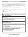
IMPORTANT SAFETY INSTRUCTIONS
READ ALL INSTRUCTIONS BEFORE USE
WARNING: For your safety, the information in this manual must be followed to minimize the risk
of fi re, explosion, or electric shock, or to prevent property damage, personal injury, or loss of life.
WARNING:
Your safety and the safety of others is very important.
We have provided many important safety messages in this manual and on your appliance. Always read and
obey all safety messages.
This is the safety alert symbol.
This symbol alerts you to potential hazards that can kill or hurt you and others.
All safety messages will follow the safety alert symbol and either the word WARNING or CAUTION.
These words mean:
Indicates a hazardous situation which, if not avoided, could result in death or serious injury.
All safety messages will tell you what the potential hazard is, tell you how to reduce the chance of injury, and
tell you what can happen if the instructions are not followed.
CAUTION:
Indicates a hazardous situation which, if not avoided, could result in minor or
moderate injury.
SAVE THESE INSTRUCTIONS
WARNING
FIRE HAZARD
Failure to follow safety hazards exactly could result in serious injury, death or property damage.
• Do not install a booster fan in the exhaust duct.
• Install all clothes dryers in accordance with the installation instructions of the manufacturer of the dryer.
WARNING
FIRE OR EXPLOSION HAZARD
Failure to follow safety hazards exactly could result in serious injury, death or property damage.
• Do not store or use gasoline or other fl ammable vapors and liquids in the vicinity of this appliance or any other
appliance.
• Installation and service must be performed by a qualifi ed installer, service agency, or the gas supplier.
WHAT TO DO IF YOU SMELL GAS:
1. Do not try to light a match or cigarette, or turn on any gas or electrical appliance.
2. Do not touch any electrical switches. Do not use any phones in your building.
3. Clear the room, building, or area of all occupants.
4. Immediately call your gas supplier from a neighbor’s phone. Carefully follow the gas supplier’s instructions
.
5. If you cannot reach your gas supplier, call the fi re department.
• Do not install a clothes dryer with fl exible plastic venting materials. If a fl exible metal (foil type) duct is
installed, it must be of a specifi c type identifi ed by the appliance manufacturer as suitable for use with clothes
dryers. Flexible venting materials are known to collapse, be easily crushed, and trap lint. These conditions will
obstruct clothes dryer airfl ow and increase the risk of fi re.

4
IMPORTANT SAFETY INSTRUCTIONS
• Read all instructions before using the dryer.
• Before use, the dryer must be properly installed, as
described in this manual.
• Do not place items exposed to cooking oils in your dryer.
Items contaminated with cooking oils may contribute to
a chemical reaction that could cause a load to catch
fi re.
• Do not dry articles that have been previously cleaned
in, washed in, soaked in, or spotted with gasoline,
dry-cleaning solvents, or other fl ammable or explosive
substances, as they give off vapors that could ignite
or explode.
• Do not reach into the dryer if the drum or any other part
is moving.
• Do not repair or replace any part of the dryer or
attempt any servicing unless specifi cally recommended
in this Use and Care Guide or in published user-repair
instructions that you understand and have the skills to
carry out.
• Do not tamper with controls.
• Before the dryer is removed from service or discarded,
remove the door to the drying compartment.
CALIFORNIA SAFE DRINKING WATER AND TOXIC ENFORCEMENT ACT
This act requires the Governor of California to publish a list of substances known to the state to cause cancer,
birth defects, or other reproductive harm and requires businesses to warn customers of potential exposure to such
substances. Gas appliances can cause minor exposure to four of these substances, namely benzene, carbon monoxide,
formaldehyde, and soot, caused primarily by the incomplete combustion of natural gas or LP fuels.
Properly adjusted dryers will minimize incomplete combustion. Exposure to these substances can be minimized further
by properly venting the dryer to the outdoors.
GROUNDING REQUIREMENTS
This appliance must be grounded. In the event of malfunction or breakdown, grounding will reduce the risk of electric
shock by providing a path of least resistance for electric current. This appliance must be equipped with a cord having
an equipment-grounding conductor and a grounding plug. The plug must be plugged into an appropriate outlet that is
properly installed and grounded in accordance with all local codes and ordinances.
WARNING: Improper connection of the equipment-grounding conductor can result in a risk of electric
shock. Check with a qualifi ed electrician or service person if you are in doubt as to whether the appliance is
properly grounded. Do not modify the plug provided with the appliance. If it will not fi t the outlet, have a proper
outlet installed by a qualifi ed electrician. This appliance must be connected to a grounded metal, permanent
wiring system or an equipment grounding conductor must be run with the circuit conductors and connected to the
equipment grounding terminal or lead on the appliance. Electrical shock can result if the dryer is not properly
grounded.
• Do not allow children to play on or in the dryer. Close
supervision of children is necessary when the dryer is
used near children.
• Do not use fabric softeners or products to eliminate
static unless recommended by the manufacturer of the
fabric softener or product.
• Do not use heat to dry articles containing foam rubber
or similarly textured rubber-like materials.
• Keep the area around the exhaust opening and adjacent
surrounding areas free from the accumulation of lint, dust,
and dirt.
• The interior of the dryer and exhaust vent should be
cleaned periodically by qualifi ed service personnel.
• Do not install or store the dryer where it will be exposed
to the weather.
• Always check the inside of the dryer for
foreign objects.
• Clean the lint fi lter before or after each load.
• Do not store plastic, paper, or clothing that may burn or
melt on top of the dryer during operation.
WARNING: This product contains chemicals known
to the State of California to cause cancer and birth
defects or other reproductive harm. Wash hands after
handling.
BASIC SAFETY PRECAUTIONS
WARNING: To reduce the risk of fi re, electric shock, or injury to persons when using this appliance,
follow basic precautions, including the following:

5
• Properly ground dryer to conform with all governing
codes and ordinances. Follow details in the installation
instructions. Electrical shock can result if the dryer is not
properly grounded.
• Before use, the dryer must be properly installed as
described in this manual. Electrical shock can result if the
dryer is not properly grounded.
• Install and store the dryer where it will not be exposed
to temperatures below freezing or exposed to
the weather.
• All repairs and servicing must be performed by an
authorized service technician unless specifi cally
recommended in this Owner’s Guide. Use only
authorized factory parts. Failure to follow this warning
can cause serious injury, fi re, electrical shock, or death.
• To reduce the risk of electrical shock, do not install the
dryer in humid spaces. Failure to follow this warning can
cause serious injury, fi re, electrical shock, or death.
• Connect to a properly rated, protected, and sized power
circuit to avoid electrical overload. Improper power
circuits can melt, creating risk of electrical shock and/or
fi re hazard.
• Gas dryers MUST be exhausted to the outside. Failure
to follow these instructions can result in fi re or death.
• The dryer exhaust system must be exhausted to the
outside of the dwelling. If the dryer is not exhausted
outdoors, some fi ne lint and large amounts of
moisture will be expelled into the laundry area. An
accumulation of lint in any area of the home can
create a health and fi re hazard.
• Use only rigid metal or fl exible metal 4 inch diameter
duct inside the dryer cabinet or for exhausting to the
outside. Use of plastic or other combustible ductwork
can cause a fi re. Punctured ductwork can cause a fi re
if it collapses or becomes otherwise restricted in use or
during installation.
• Ductwork is not provided with the dryer, and you
should obtain the necessary ductwork locally. The end
cap should have hinged dampers to prevent backdraft
when the dryer is not in use. Failure to follow these
instructions can result in fi re or death.
• Remove all packing items and dispose of all shipping
materials properly. Failure to do so can result in death,
fi re, explosion, burns, or death.
• Place dryer at least 18 inches above the fl oor for a
garage installation. Failure to do so can result in fi re,
explosion, burns, or death.
• Keep all packaging from children. Packaging material
can be dangerous for children. There is a risk of
suff ocation.
• Do not install near items that produce heat or open
fl ame such as stoves or cooking ovens. Failure to follow
this warning can cause product deformation, smoke and
fi re.
• Do not place candles, smoking materials, or other
fl ammables on top of the product. Dripping wax, smoke,
or fi re can result.
• Remove all protective vinyl fi lm from the product. Failure
to do so can cause product damage, smoke or fi re.
• The exhaust duct must be 4 inches (10.2 cm) in
diameter with no obstructions. The exhaust duct should
be kept as short as possible. Make sure to clean any
old ducts before installing your new dryer. Failure to
follow these instructions can result in fi re or death.
• Rigid or semi rigid metal ducting is recommended
for use between the dryer and the wall. In special
installations when it is impossible to make a connection
with the above recommendations, a UL listed fl exible
metal transition duct may be used between the dryer
and wall connection only. The use of this ducting will
aff ect drying time. Failure to follow these instructions
can result in fi re or death.
• DO NOT use sheet metal screws or other fasteners
which extend into the duct that could catch lint and
reduce the effi ciency of the exhaust system. Secure all
joints with duct tape. For complete details, follow the
Installation Instructions. Failure to follow these instructions
can result in fi re or death.
SAFETY INSTRUCTIONS FOR INSTALLATION
Exhaust/Ducting:
WARNING: To reduce the risk of fi re, electric shock, or injury to persons when using this appliance,
follow basic precautions, including the following:
IMPORTANT SAFETY INSTRUCTIONS

6
SAFETY INSTRUCTIONS FOR CONNECTING ELECTRICITY
• Do not, under any circumstances, cut or remove the
ground prong from the power cord. To prevent personal
injury or damage to the dryer, the electrical power cord
must be plugged into a properly
grounded outlet.
• For personal safety, this dryer must be properly
grounded. Failure to do so can result in electrical shock
or injury.
• Refer to the installation instructions in this manual for
specifi c electrical requirements for your model. Failure
to follow these instructions can create an electrical shock
hazard and/or a fi re hazard.
• This dryer must be plugged into a properly grounded
outlet. Electrical shock can result if the dryer is not
properly grounded. Have the wall outlet and circuit
checked by a qualifi ed electrician to make sure the
outlet is properly grounded. Failure to follow these
instructions can create an electrical shock hazard
and/or a fi re hazard.
• The dryer should always be plugged into its own
individual electrical outlet which has a voltage rating
that matches the rating plate. This provides the best
performance and also prevents overloading house wiring
circuits which could cause a fi re hazard from overheated
wires.
• Never unplug your dryer by pulling on the power cord.
Always grip the plug fi rmly and pull straight out from
the outlet. The power cord can be damaged, resulting in
a risk of fi re and electrical shock.
• Repair or replace immediately all power cords that
have become frayed or otherwise damaged. Do not
use a cord that shows cracks or abrasion damage
along its length or at either end. The power cord can
melt, creating electrical shock and/or fi re hazard.
• When installing or moving the dryer, be careful not
to pinch, crush, or damage the power cord. This will
prevent injury and prevent damage to the dryer from
fi re and electrical shock.
SAVE THESE INSTRUCTIONS
WARNING: To reduce the risk of fi re, electric shock, or injury to persons when using this appliance,
follow basic precautions, including the following:
IMPORTANT SAFETY INSTRUCTIONS

7
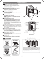
FEATURES AND BENEFITS
KEY PARTS AND COMPONENTS
EASY-TO-USE CONTROL PANEL
Select the desired dry cycle, add cycle options or
adjust settings with the touch of a button.
TIME AND STATUS DISPLAY
The easy-to-read LED display shows cycle status and
estimated time remaining.
CYCLE MODIFIERS
Adjust the cycle defaults such as temperature and dry
level with the touch of a button.
NOTE: Not all settings are available for all cycles.
CHECK VENT
(Duct Blockage Sensing System)
The CHECK VENT (Duct blockage sensing system)
detects and alerts you to blockages in the exhaust
system that reduce airfl ow from the dryer.
Maintaining clean exhaust system ducts improves
operating effi ciency and helps minimize service calls,
saving you money.
LARGE CAPACITY STEEL DRUM WITH DRUM LIGHT
The ultra-large, oxidation-resistant, coated steel drum
off ers superior durability. The light comes on when the
door is opened.
EASY-ACCESS REVERSIBLE DOOR
The wide-opening, see-through glass door provides
easy access for loading and unloading. Door swing
can be reversed to adjust for installation location.
FRONT-MOUNT LINT FILTER
The front-mount lint fi lter allows for easy access and
cleaning between loads.
LEVELING FEET
Four leveling feet (two in front, and two in back)
adjust to improve dryer stability on uneven fl oors.
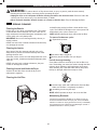
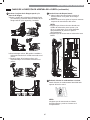
There are several important components that are
referenced in this manual.
A
B
C
D
E
F
G
H
Rear of Dryer
Terminal
block
access panel
(Electric
models)
Gas
connection
location
(Gas models)
Power cord
location
(Gas
models)
Exhaust
duct
outlet
Water Inlet
Valve
ACCESSORIES
H
G
A D B
E
F
C
Included Accessories
Optional Accessories
(sold separately)
Hoses and Y connector*
Kit No. 26-59029
Side vent kit*
Kit No. 26-49670
Drying rack**
Part No. 3750EL0001C
Safety tether kit
* at Sears.com
** at SearsPartsDirect.com
Required Accessories
(sold separately)
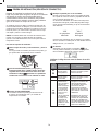
The two-way reversible door feature allows you to open the dryer
door from the top, hamper-style, when loading the dryer to help guide
clothes into the drum and prevent them from falling onto the floor.
When unloading the dryer or loading bulkier items, use the swing door
for easy access to the drum.
hamper door
swing door
release
Two-Way Reversible Door

8
INSTALLATION INSTRUCTIONS
KEY DIMENSIONS AND SPECIFICATIONS
CHOOSE THE PROPER LOCATION
• A location that allows for proper exhaust installation.
A gas dryer must be exhausted to the outdoors. See
Venting the Dryer.
• A grounded electrical outlet located within 2 ft. (61
cm) of either side of the dryer. See Connecting Electric
Dryers.
• A sturdy fl oor to support the total dryer weight of 200
lbs (90.7 kg). The combined weight of a companion
appliance should also be considered.
• No other fuel-burning appliance can be installed in the
same closet as a dryer.
• Store and install the dryer where it will not be exposed
to temperatures below freezing or exposed to outdoor
weather conditions.
• Choose a location with a solid, level fl oor with a
maximum slope of 1 inch (2.5 cm) under the entire
dryer. If the slope is greater than 1 inch (2.5 cm), install
the Extended Dryer Feet Kit. Clothes may not tumble
properly, and automatic sensor cycles may not operate
correctly if the dryer is not level.
• If the dryer is being installed in a garage, place the
dryer at least 18 inches (45.7cm) above the fl oor. If
using a pedestal, you will need 18 inches (46 cm) to the
bottom of the dryer.
• To reduce the risk of electric shock, do not install the
dryer in damp or wet locations.
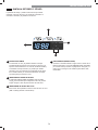
Description Dryer Steam Dryer (Gas and Electric)
Electrical Requirements Refer to the rating label
Gas Requirements* NG: 4–10.5 inches WC
Gas Requirements* LP: 8–13 inches WC
Dimensions
27 in. (W) X 29 ½ in. (D) X 40 3/16 in. (H), 50
¼
in. (D with door open)
68.6 cm (W) X 75 cm (D) X 102 cm (H), 127.5 cm (D with door open)
Net Weight Electric : 135.1 lb. (61.3 kg) Gas : 137.8 lb. (62.5 kg)
Drying Capacity IEC 7.3 cu.ft. (22.5 lb/10.2 kg)
*Gas Models Only
Do not operate your dryer at temperatures below 45°F
(7°C). At lower temperatures, the dryer might not shut off
at the end of an automatic cycle. This can result in longer
drying times. The dryer must not be installed or stored
in an area where it will be exposed to water and/or
weather. Check code requirements. Some codes limit, or
do not permit, installation of the dryer in garages, closets,
mobile homes or sleeping quarters. Contact your local
building inspector.
NOTE: Installing the dryer in a humid space, or installing
or storing the dryer where it will be exposed to the
weather or freezing temperatures, may result in rust
or other damage that is not covered by the product
warranty.
IMPORTANT: If you are installing your dryer in a
manufactured or mobile home, please refer to the
Special Electrical Requirements for Mobile or
Manufactured Homes section.
LOCATION REQUIREMENTS
IMPORTANT: Read all installation instructions completely before installing and operating your dryer.
It is important that you review this entire manual before installing and using your dryer. It contains detailed instructions
concerning electrical connections, gas connections and exhaust requirements.
CLEARANCES
• Most installations require a minimum 5 ½ inch (14 cm)
clearance behind the dryer for the exhaust ducting.
• Allow minimum clearances of at least 1 inch (2.5 cm) on
the sides and back to minimize vibration and noise.
• Allowing additional clearance for installation and
servicing is recommended.
• Be sure to allow for wall, door, or fl oor moldings that
may increase the required clearances.
• Allow at least 21 inches (53.3 cm) in front of the dryer to
open the door.

9
Additional instructions for closet installations:
The closet door must allow for suffi cient airfl ow. Refer
to the diagram above for minimum vent opening
requirements. A louvered door is also acceptable.
Closet Door Vent Requirements
(7.6 cm)
(7.6 cm)
(2.54 cm) (2.54 cm)(68.6 cm)
14
"
max.*
(35.6
cm)
21
1
/
4
"
(54 cm)
29
1
/
2
"
(75 cm)
50
1
/
4
"
(127.5 cm)
5"**
(12.7 cm)
40
3
/
16
"
(102 cm)
CLEARANCES (continued)
Recommended installation spacing for cabinet installation:
For cabinet installation with a door, minimum ventilation
openings in the top of the cabinet are required.
*Required spacing
**For side or bottom venting,
2-inch (5.1 cm) clearance is allowed.
29 ½"
(75 cm)
7"* (17.8 cm)
7"* (17.8 cm)
5"*
(12.7 cm)
1"*
(2.5 cm)
(68.6 cm)
1"
(2.54 cm)
1"
(2.54 cm)
27
"
INSTALLATION INSTRUCTIONS

10
GAS DRYERS
GAS REQUIREMENTS (GAS MODELS ONlY)
• Gas supply requirements: As shipped from the factory,
this dryer is confi gured for use with natural gas (NG).
It can be converted for use with propane (LP) gas. Gas
pressure must not exceed 8 inches water column for
(NG), or 13 inches water column for (LP).
• A qualifi ed service or gas company technician must
connect the dryer to the gas service. Failure to follow
these instructions can result in fi re, explosion, or death.
• Isolate the dryer from the gas supply system by closing
its individual manual shutoff valve during any pressure
testing of the gas supply. Failure to do so can result in
fi re, explosion, or death.
• Supply line requirements: Your laundry room must
have a rigid gas supply line to your dryer. In the United
States, an individual manual shutoff valve MUST be
installed within at least 6 ft. (1.8 m) of the dryer, in
accordance with the National Fuel Gas Code ANSI
Z223.1 or Canadian gas installation code CSA B149.1. A
⅛ inch NPT pipe plug must be installed. Failure to do
so can result in fi re, explosion, or death.
• If using a rigid pipe, the rigid pipe should be ½ inch
IPS. If acceptable under local codes and ordinances
and when acceptable to your gas supplier, ⅜ inch
approved tubing may be used where lengths are less
than 20 ft. (6.1 m). Larger tubing should be used for
lengths in excess of 20 ft. (6.1 m). Failure to do so can
result in fi re, explosion, or death.
• Do not, under any circumstances, cut or remove the
third (ground) prong from the power cord. Failure to
follow this warning can result in fi re, explosion, or death.
• For personal safety, this dryer must be properly
grounded. Failure to follow this warning can result in fi re,
explosion, or death.
• The power cord of this dryer is equipped with a
3-prong (grounding) plug which mates with a standard
3-prong (grounding) wall outlet to minimize the
possibility of electric shock hazard from this appliance.
Failure to follow this warning can result in fi re, explosion,
or death.
• This dryer must be plugged into a 120-VAC, 60-Hz.
grounded outlet protected by a 15-ampere fuse or
circuit breaker. Failure to follow this warning can result
in fi re, explosion, or death.
• Where a standard 2-prong wall outlet is encountered, it
is your personal responsibility and obligation to have it
replaced with a properly grounded 3-prong wall outlet.
Failure to follow this warning can result in fi re, explosion,
or death.
• Connect the dryer to the type of gas shown on the
nameplate. Failure to do so can result in fi re, explosion,
or death.
• To prevent contamination of the gas valve, purge the
gas supply of air and sediment before connecting
the gas supply to the dryer. Before tightening the
connection between the gas supply and the dryer,
purge remaining air until the odor of gas is detected.
Failure to do so can result in fi re, explosion, or death.
• DO NOT use an open fl ame to inspect for gas leaks.
Use a noncorrosive leak detection fl uid. Failure to do so
can result in fi re, explosion, or death.
• Use only a new AGA- or CSA-certifi ed gas supply line
with fl exible stainless steel connectors. Failure to do so
can result in fi re, explosion, or death.
• Securely tighten all gas connections. Failure to do so
can result in fi re, explosion, or death.
• Use Tefl on tape or a pipe-joint compound that is
insoluble in propane (LP) gas on all pipe threads.
Failure to do so can result in fi re, explosion,
or death.
• DO NOT attempt any disassembly of the dryer;
disassembly requires the attention and tools of an
authorized and qualifi ed service technician or company.
Failure to follow this warning can result in fi re, explosion,
or death.
3-prong
grounding
plug
3-prong
grounding
type wall
receptacle
Ensure proper
ground exists
before use.
ELECTRICAL REQUIREMENTS (GAS MODELS ONLY)
WARNING: To reduce the risk of fi re, electric shock, or injury to persons when using this appliance,
follow basic precautions, including the following:
INSTALLATION INSTRUCTIONS

11
• Installation and service must be performed by a
qualifi ed installer, service agency, or the gas supplier.
Failure to do so can result in fi re, explosion, or death.
• Use only a new stainless steel fl exible connector and a
new AGA-certifi ed connector. Failure to do so can result
in fi re, explosion, or death.
• A gas shutoff valve must be installed within 6 ft.
(1.8 m) of the dryer. Failure to do so can result in fi re,
explosion, or death.
• The dryer is confi gured for natural gas when shipped
from the factory. Make sure that the dryer is equipped
with the correct burner nozzle for the type of gas being
used (natural gas or propane gas). Failure to do so can
result in fi re, explosion, or death.
CONNECTING THE GAS SUPPLY
NOTE: This dryer is confi gured from the factory set for
natural gas (NG). If dryer is to be used with propane (LP)
gas, it must be converted by a qualifi ed
service technician.
1
Make sure that the gas supply to the laundry room is
turned OFF and the dryer is unplugged. Confi rm that
the type of gas available in your laundry room is
appropriate for the dryer.
2
Remove the shipping cap from the gas fi tting at the
back of the dryer. Be careful not to damage the
threads of the gas connector when removing the
shipping cap.
3
Connect the dryer to your laundry room’s gas supply
using a new fl exible stainless steel connector with a
⅜-inch NPT fi tting.
NOTE: DO NOT use old connectors.
4
Securely tighten all connections between the dryer and
your laundry room’s gas supply.
5
Turn on your laundry room’s gas supply.
6
Check all pipe connections (both internal and external)
for gas leaks with a noncorrosive leak-detection fl uid.
7
Proceed to Venting the Dryer (refer to pages 14-15).
High-Altitude Installations
The BTU rating of this dryer is AGA-certifi ed for
elevations below 10,000 feet.
If your gas dryer is being installed at an elevation
above 10,000 feet, it must be derated by a qualifi ed
technician or gas supplier.
• If necessary, the correct nozzle (for the LP nozzle kit,
order part number 17025) should be installed by a
qualifi ed technician and the change should be noted on
the dryer. Failure to do so can result in fi re, explosion, or
death.
• All connections must be in accordance with local codes
and regulations. Failure to do so can result in fi re,
explosion, or death.
• Gas dryers MUST exhaust to the outdoors. Failure to do
so can result in fi re, explosion, or death.
GAS DRYERS (continued)
3/8" NPT Gas
Connection
Gas Supply
6KXWRç9DOYH
$*$&6$&HUWLoHG
Stainless Steel
Flexible Connector
1/8" NPT Pipe Plug
WARNING: To reduce the risk of fi re, electric shock, or injury to persons when using this appliance,
follow basic precautions, including the following:
INSTALLATION INSTRUCTIONS

12
ELECTRIC DRYERS
ELECTRICAL REQUIREMENTS
WARNING: To help prevent fi re, electrical
shock, serious injury, or death, the wiring and
grounding must conform to the latest edition of
the National Electrical Code, ANSI/NFPA 70 and
all applicable local regulations. Please contact a
qualifi ed electrician to check your home’s wiring
and fuses to ensure that your home has adequate
electrical power to operate the dryer.
• Any installation in a manufactured or mobile home must
comply with the Manufactured Home Construction and
Safety Standards Title 24 CFR, Part 32-80 or Standard
CAN/CSA0Z240 MH and local codes and ordinances.
• A 4-wire connection is required for all mobile and
manufactured home installations, as well as all new
construction after January 1, 1996. Failure to do so can
result in fi re, explosion, or death.
• A gas dryer must be permanently attached to the fl oor.
• To reduce the risk of combustion and fi re, the dryer must
be vented to the outside.
• DO NOT vent the dryer under a manufactured home or
mobile home.
• Electric dryers may be vented to the outside using the
back, left, right, or bottom panel.
• Gas dryers may be vented to the outside using the back,
left, or bottom panel. Gas dryers may not be vented
to the outside using the right side panel because of the
burner housing.
• The dryer exhaust duct must be affi xed securely to the
manufactured or mobile home structure, and the exhaust
duct must be made of a material that will resist fi re and
combustion. It is recommended that you use a rigid or
fl exible metal duct.
• DO NOT connect the dryer exhaust duct to any other
duct, vent, chimney, or other exhaust duct.
• Make sure the dryer has adequate access to outside fresh
air to ensure proper operation. The opening for outside
fresh air must be at least 25 in
2
(163 cm
2
).
• It is important that the clearance of the duct from any
combustible construction be at least 2 inches (5 cm), and
when venting the dryer to the outdoors, the dryer can be
installed with a clearance of 1 inch (2.5 cm) at the sides
and back of the dryer.
• Please be aware that venting materials are not supplied
with the dryer. You should obtain the venting materials
necessary for proper installation.
• This dryer must be connected to a grounded metal,
permanent wiring system, or an equipment grounding
conductor must be run with the circuit conductors and
connected to the equipment grounding terminal or
lead on the dryer. Failure to do so can result in fi re,
explosion, or death.
• The dryer has its own terminal block that must be
connected to a separate 240 VAC, 60-Hertz, single
phase circuit, fused at 30 amperes (the circuit must be
fused on both sides of the line). ELECTRICAL SERVICE
FOR THE DRYER SHOULD BE OF THE MAXIMUM
RATE VOLTAGE LISTED ON THE NAMEPLATE. DO
NOT CONNECT DRYER TO 110-, 115-, OR 120-VOLT
CIRCUIT. Failure to follow these instructions can result in
fi re, explosion, or death.
• If branch circuit to dryer is 15 ft. (4.5 m) or less in
length, use UL (Underwriters Laboratories) listed No.-
10 AWG wire (copper wire only), or as required by
local codes. If over 15 ft. (4.50 m), use UL-listed No.-8
AWG wire (copper wire only), or as required by local
codes. Allow suffi cient slack in wiring so dryer can
be moved from its normal location when necessary.
Failure to do so can result in fi re, explosion, or death.
• The power cord (pigtail) connection between wall
receptacle and dryer terminal block IS NOT supplied
with the dryer. Type of pigtail and gauge of wire must
conform to local codes and with instructions on the
following pages. Failure to follow these instructions can
result in fi re, explosion, or death
• A 4-wire connection is required for all new
construction after January 1, 1996. A 4-wire connection
must be used where local codes do not permit
grounding through the neutral wire. Failure to do so
can result in fi re, explosion, or death.
Special Electrical Requirements for Mobile
or Manufactured Homes
Electrical Requirements for Electric Models Only
WARNING: To reduce the risk of fi re,
electric shock, or injury to persons when using this
appliance,
follow basic precautions, including the
following:
WARNING: To reduce the risk of fi re,
electric shock, or injury to persons when using this
appliance,
follow basic precautions, including the
following:
INSTALLATION INSTRUCTIONS

13
ELECTRIC DRYERS (continued)
CONNECTING ELECTRIC DRYERS
Connect the power cord to the terminal block. Each
colored wire should be connected to the terminal block
screw with the same color wire around it. For example,
connect the black power cord wire to the terminal block
screw with the black wire around it. Failure to follow
these instructions may result in a short or overload.
Four-Wire Power Cord
• A 4-wire connection is required for all mobile
and manufactured home installations, as well
as all new construction after January 1, 1996.
• A UL-listed strain relief is required.
• Use a 30-amp, 240-volt, 4-wire, UL-listed power cord
with #10 AWG-minimum copper conductor and closed
loop or forked terminals with upturned ends.
1
Remove the terminal block access cover on the upper
back of the dryer.
2
Install a UL-listed strain relief into the power cord
through-hole.
3
Thread a 30-amp, 240-volt, 4-wire, UL-listed power
cord with #10 AWG-minimum copper conductor
through the strain relief.
4
Transfer the dryer’s ground wire from behind the green
ground screw to the center screw of the terminal block.
5
Attach the two hot leads of the power cord to the outer
terminal block screws.
6
Attach the white neutral wire to the center screw of the
terminal block.
7
Attach the power cord ground wire to the green ground
screw.
8
TIGHTEN ALL SCREWS SECURELY.
9
Reinstall the terminal block access cover.
4
Attach the two hot leads (black and red) of the power
cord to the outer terminal block screws.
5
Attach the neutral (white) wire to the center terminal
block screw.
6
Connect the external ground (if required by local
codes) to the green ground screw.
7
TIGHTEN ALL SCREWS SECURELY.
8
Reinstall the terminal block access cover.
Grounding through the neutral conductor is prohibited
for: (1) new branch-circuit installations, (2) mobile
homes, (3) recreational vehicles, and (4) areas where
local codes prohibit grounding through the neutral
conductor.
Three-Wire Power Cord
• A 3-wire connection is NOT permitted on
new construction after January 1, 1996.
• A UL-listed strain relief is required.
• Use a 30-amp, 240-volt, 3-wire, UL-listed power cord
with #10 AWG-minimum copper conductor and closed
loop or forked terminals with upturned ends.
1
Remove the terminal block access cover on the upper
back of the dryer.
2
Install a UL-listed strain relief into the power cord
through-hole.
3
Thread a 30-amp, 240-volt, 3-wire, UL-listed power
cord with #10 AWG-minimum copper conductor
through the strain relief.
WARNING:
UL-Listed
Strain Relief
UL-Listed 4-Wire
Power Cord
Terminal
Block
UL-Listed
Strain Relief
UL-Listed 3-Wire
Power Cord
Terminal
Block
Power Cord
Ground Wire
White wire moved
from ground screw
Ground Screw
Hot (Red)
Neutral
(White)
Hot
(Black)
White wire from
dryer harness
Ground Screw
Hot (Red)
Neutral
(White)
Hot
(Black)
INSTALLATION INSTRUCTIONS

14
VENTING THE DRYER
CHECK YOUR EXHAUST SYSTEM FOR PROBLEMS
IMPORTANT!
The most common cause of dryer problems is poor exhaust venting. Before installing your new dryer, check the items
listed below to make sure you get the best possible performance. This can save you time and money by reducing cycle
times and increasing energy effi ciency.
• DIRTY OR DAMAGED EXHAUST DUCTS. Lint builds up in exhaust ducts over time. This decreases the airfl ow and
makes the dryer work harder. Visually inspect your ducts from both ends and have them cleaned if they have not been
cleaned recently.
• WRONG VENT MATERIAL. Check your vent to make sure it is rigid or semi-rigid metal ducting. If your venting is
plastic or fl exible foil, have it replaced before using the dryer.
• RESTRICTED OR DAMAGED VENT HOOD. Check your vent hood outside. It must be clean and free of lint buildup.
Check the damper and make sure it opens fully and easily.
• EXCESSIVELY LONG VENT. Measure the length of your exhaust system and count the elbows. Use the chart below to
see if your duct is too long. If it is too long, have the duct routed to another location that is within the
venting guidelines.
• DO NOT USE PLASTIC OR FOIL VENTING. The transition duct from your dryer to the wall must be rigid or
semi-rigid metal ducting. If your old transition duct is plastic or foil, REPLACE IT with semi-rigid metal ducting.
Using the DUCT LENGTH CHART (below)
1
Find your vent hood type in the chart below.
2
Select the row that matches the number of elbows in your dryer duct run.
3
Look to the right of the elbow number for the maximum duct length for your installation. Longer duct length will result
in reduced drying performance, longer dry times and increased energy consumption. Extremely long ducts can even
shorten the life of the dryer.
DO NOT exceed the maximum length for the vent hood type and number of elbows used.
DUCT LENGTH CHART
NOTE: Deduct 6 ft. (1.8 m) for each additional elbow. Using more than four 90° elbows is not recommended.
Recommended
Only for Short-Run Installations
4"
(10.2 cm )
4"
(10.2 cm )
(6.35 cm )
Number of 90°
Elbows
Vent Hood Type
Maximum length of 4" (10.2 cm )
diameter rigid metal duct
65 feet (19.8 m)
55 feet (16.8 m)
47 feet (13.7 m)
36 feet (11.0 m)
28 feet (8.5 m)
55 feet (16.8 m)
47 feet (13.7 m)
41 feet (12.5 m)
30 feet (9.1 m)
22 feet (6.7 m)
0
1
2
3
4
0
1
2
3
4
2 ½"
INSTALLATION INSTRUCTIONS

15
VENTING THE DRYER (continued)
Routing and Connecting Ductwork
Follow the guidelines below to maximize dryer
performance and reduce lint buildup and condensation in
the ductwork.
NOTE: Transition duct and fi ttings are NOT included and
must be purchased separately.
• Use 4 inch (102mm) diameter rigid or semi-rigid
metal duct.
• The exhaust duct run should be as short as possible.
• Use as few elbow joints as possible.
• The male end of each section of exhaust duct must point
away from the dryer.
• Use duct tape on all joints. Never use screws.
• Insulate ducts that runs through unheated areas in order
to reduce condensation and lint buildup on
duct surfaces.
• The total length of semi-rigid metal transition duct
should not exceed 8 ft. (2.4 m).
IMPORTANT: Failure to exhaust the dryer, per the
guidelines included within these instructions, may
result in unsatisfactory dryer performance. All venting
and ductwork beyond the exterior of the dryer is the
responsibility of the consumer. Product failure, as a result
of improper venting, is not covered by the manufacturer’s
warranty.
Connecting the Dryer Vent
1
Verify all ducts and elbows are clean and free from
any blockages.
2
Measure duct length. DO NOT exceed the maximum
length listed in the Duct Length Chart.
3
Connect dryer exhaust to existing duct.
• Only use duct tape or clamps.
• DO NOT use screws to secure ductwork.
• Use rigid or semi-rigid metal ducts.
• DO NOT use plastic or thin metal foil tubing
for ductwork.
• The male end of each elbow must always point in the
direction of the airfl ow.
NOTE: Be careful when moving the dryer into its
fi nal location. Do NOT crush the duct. Make sure the
connections do not come loose.
WARNING: Failure to follow these
guidelines will result in poor performance and product
failure, and may result in fi re or death.
Male
Ends
Correct Venting
Incorrect Venting
INSTALLATION INSTRUCTIONS

16
CONNECTING THE INLET HOSE
The dryer must be connected to the cold water tap using
the new water supply hose. Do not use old hoses.
NOTE:
• Water supply pressure must be between 20psi and
120psi (138–827 kPa).
• Do not strip or cross-thread when connecting inlet hose
to the valve.
• If the water supply pressure is more than 120psi
(827kPa), a pressure reducing valve should be installed.
• Periodically check the condition of the hose and replace
the hose if necessary.
• Replace inlet hoses after 5 years of use to reduce the
risk of hose failure.
• Record hose installation or replacement dates on the
hoses for future reference.
1
Check the rubber seals in the inlet hose. Two rubber
seals are supplied with the inlet hose. They are used for
preventing water leaks. Make sure the connection to
the cold water tap is tight.
Hose
connector
Y connector
Rubber
seal
2
Check the installation type.
Long
hose
WITH WASHER WITHOUT WASHER
Short
hose
Y connector
Connect all water supply hoses tightly by hand and
then tighten another 2/3 turn with pliers.
WITH WASHER: When connecting the dryer to the
same faucet as a washer.
a. Shut off the cold water tap and remove the washer
hose.
b. Connect the short hose to the Y-connector.
c. Connect the other end of the short hose to the cold
water faucet.
d. Connect the long dryer hose to one side of the Y-connector
and connect the washer hose to the other side.
WITHOUT WASHER: If the dryer does not share the
cold water tap with a washer.
a. Connect the straight end of the long hose to the cold
water faucet.
NOTE:
• Before connecting the water line to the dryer, fl ush
several gallons of water through the hose into
a drain or bucket. This will help prevent foreign
particles such as sand and scale from clogging the
dryer inlet valve.
• Do not overtighten. Damage to the coupling can
result.
3
Connect the hose to the dryer.
Connect the water supply hose to the dryer inlet valve
tightly by hand and then tighten another 2/3 turn
with pliers. Make sure that there are no kinks in the
hoses and that they are not crushed.
4
Turn on the cold water faucet.
5
Check for leaks at the Y-connector (if used) and all
hoses.
NOTE:
• If any leaks are found, shut off the water faucet,
remove the hose and check the condition of the hose
washer.
INSTALLATION INSTRUCTIONS

17
LEVELING THE DRYER
To ensure that the dryer provides optimal drying
performance, it must be level. To minimize vibration,
noise, and unwanted movement, the fl oor must be a level,
solid surface.
NOTE: Adjust the leveling feet only as far as necessary
to level the dryer. Extending the leveling feet more than
necessary can cause the dryer to vibrate.
WARNING:
• To reduce the risk of injury to persons, adhere
to all industry recommended safety procedures
including the use of long sleeved gloves and
safety glasses. Failure to follow this warning can
cause serious injury or death.
• The appliances are heavy. Two or more people
are required when installing the dryer. Failure to
follow this warning can cause serious injury or
death.
1
Position the dryer in the fi nal location. Place a level
across the top of the dryer.
Level
Levelin
g
Feet
All four leveling feet must rest solidly on the fl oor.
Gently push on the top corners of the dryer to make
sure that the dryer does not rock from corner to corner.
2
Use a wrench to turn the leveling feet. Turn the leveling
foot clockwise to raise the dryer or counterclockwise
to lower the dryer. Using a level, adjust the feet until
the dryer is level from side to side and front to back.
Make sure all four feet are in fi rm contact with the
fl oor.
NOTE: If you are installing the dryer on the optional
pedestal, the dryer leveling feet should be fully retracted.
Use the leveling feet on the pedestal to level the dryer.
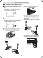
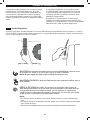
REVERSING THE DOOR SWING
WARNING:
THE DRYER DOOR IS VERY LARGE AND HEAVY.
Failure to follow the instructions below can result
in damage to the dryer, property damage or
personal injury.
• To avoid damage to the dryer or the door, support
the door with a stool or box that fits under the
door, or have an assistant support the weight of
the door.
• Avoid dropping the door to avoid damage to the
door or the floor.
• Unplug the dryer or turn off power at the main
circuit breaker before beginning door reversal.
Tools Required
Phillips or large flat-blade screwdriver (for hinge
screws)
Small flat blade screwdriver
(for lifting out parts)
Door Reversal Instructions
NOTE: The instructions here are for changing the door
swing from a right to a left side hinge. If the door has
been reversed, and it is necessary to change it back,
use care when following these instructions. Some of the
illustrations and the left/right references will be reversed,
and you will need to read the instructions carefully.
Swing Door
1
Open the door from the side so that the hinge screws
are accessible.
WARNING:
Be sure to support the weight of the door before
removing the hinge screws.
2
Remove the 4 hinge screws.
While supporting the door, remove the 4 hinge screws,
2 from each hinge. Set the door aside face down on a
protected surface to prevent damage to the door or
the work surface.
Two large
screws
Two small
screws
INSTALLATION INSTRUCTIONS

18
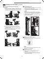
3
Reverse the components on the cabinet.
a. Use a Phillips screwdriver to remove the 2 screws and
the latch mechanism on the front panel of the cabinet.
b. Remove the latch hole cover by gently prying it up
with a flat-blade screwdriver, being careful not to
scratch the paint. Install the latch hole cover on
the opposite side, where the latch mechanism was
removed. Install the latch mechanism in the position
from which you removed the latch hole cover, using
the two screws removed in step a.
c. Remove the hinge cover by gently prying it up with a
flat-blade screwdriver, being careful not to scratch
the paint. Rotate the hinge cover 180 degrees and
install it on the opposite side, where the upper hinge
was attached.
4
Remove the inner door frame.
With the door on a protected surface, remove the 16
screws around the sides of the door and lift off the
inner door frame using a flat blade screwdriver.
Remove the latch hook and blank and install them on
the opposite side.
5
Reverse hinges and cover caps.
Remove the 4 screws securing the hinges to the door
frame. Remove the 2 plastic cover caps. Reinstall the
hinges and cover caps on the opposite sides from
which they were removed.
hinge
hinge
cover
hinge
cover
latch
mechanism
latch
hole
cover
hinge
frame
Blank Latch hook
Inner door
Cover cap
Hinge
assembly
6
Remount the inner door frame.
With the hinges and cover caps in the new locations,
remount the inner door frame onto the outer door
frame with the screws removed in step 4.
WARNING:
Be sure to support the weight of the door before
installing the hinge screws.
7
Reinstall the door.
While supporting the door, install the 4 hinge screws
removed in step 2. Test the swing of the door to make
sure the hinges and latch are properly aligned and
that the door opens, closes, and latches properly.
Door
Swing
REVERSING THE DOOR SWING (continued)
INSTALLATION INSTRUCTIONS

19
REVERSING THE DOOR SWING (continued)
b. Lift the door slightly to disengage the hinge support
and remove the door from the cabinet.
3
Reverse the components on the cabinet.
a. Use a Phillips screwdriver to remove the 2 screws and
the latch mechanism on the front panel of the cabinet.
b. Remove the latch hole cover by gently prying it up
with a flat-blade screwdriver, being careful not to
scratch the paint. Install the latch hole cover on
the opposite side, where the latch mechanism was
removed. Install the latch mechanism in the position
from which you removed the latch hole cover, using
the two screws removed in step a.
c. Remove the hinge cover by gently prying it up with a
flat-blade screwdriver, being careful not to scratch
the paint. Rotate the hinge cover 180 degrees and
install it on the opposite side, where the upper hinge
was attached.
d. Reverse the hinge and the hinge bracket at the
bottom of the cabinet. Remove the 2 screws from
the hinge bracket at bottom right and remove the
hinge bracket. Remove the lower of the 2 screws
behind the hinge bracket. Do NOT remove the
upper screw behind the hinge bracket. Set the parts
aside.
Upper
hinge
Hinge
cover
Hinge
latch
mechanism
Latch
hole
cover
Hinge
bracket
Two-Way Door (on some models)
Before You Begin
NOTE:
The door reversal procedure for the two-way door is far
more complex than for a conventional dryer door. It is
recommended that you read through these instructions
in their entirety before beginning the process, in order to
gauge whether you prefer to have the procedure done by
a professional installer or service person.
The instructions here are for changing the door swing
from a right to a left side hinge. If the door has been
reversed, and it is necessary to change it back, use care
when following these instructions. Some of the illustrations
and the left/right references will be reversed, and you will
need to read the instructions carefully.
Tools Required
Phillips or large flat-blade screwdriver (for hinge
screws)
Small flat blade screwdriver
(for lifting out parts)
WARNING:
THE DRYER DOOR IS VERY LARGE AND HEAVY.
Failure to follow the instructions below can result
in damage to the dryer, property damage or
personal injury.
• To avoid damage to the dryer or the door, support
the door with a stool or box that fits under the
door, or have an assistant support the weight of
the door.
• Avoid dropping the door to avoid damage to the
door or the floor.
• Unplug the dryer or turn off power at the main
circuit breaker before beginning door reversal.
Instructions
1
Open the door from the side so that the hinge screws
are accessible.
WARNING:
Be sure to support the weight of the door before
removing the hinge screws.
2
Remove the door from the cabinet.
a. While supporting the door, remove the 4 hinge
screws.
screws
Two large
screws
Two small
INSTALLATION INSTRUCTIONS

20
NOTE:
Do NOT remove any of the 8 screws on the face
of the cabinet (marked with
below). Doing so
could result in damage to the dryer and the need
for a service call to repair the dryer.
e. Remove the 3 screws on the hinge at bottom left.
Remove the hinge and reinstall it on the right side.
The top screw occupies the hole where you removed
the screw behind the hinge bracket in step d.
f. Install the hinge bracket removed in step d on the
bottom left side, first installing 1 screw behind the
hinge bracket.
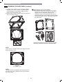
On the Door:
CAUTION:
The edges of the door cover may be sharp. Wear
gloves when handling to avoid injury.
4
Lift off the door cover.
With the door laid inside facing up on a protected
surface, remove the 12 screws on the inside of the
door. Carefully lift off the door cover with the help of
a small flat-blade screwdriver inserted in the upper
corner (circled below).
hinge
cover
hinge
bracket
latch hole
cover
latch
mechanism
hinge
Cabinet Reversal complete
Hole
plug
Twelve screws
Side
Interlock
button
5
Switch the door strike and the blank cover.
Remove the 2 screws on the door cover that secure the
door strike.
Switch the door strike and the blank cover, installing
them on the opposite sides from which they were
removed.
It may be difficult to insert the 2 screws in the door
strike on the opposite side. Use a cordless screwdriver
if necessary.
Gently pry out the hole plug on the side of the door
cover and install it in the hole on the opposite side.
Set the door cover aside.
screw
Long
Short
screws
Blank cover Door strike
Pull
Raise
Remove blank cover
Hole
plug
REVERSING THE DOOR SWING (continued)
INSTALLATION INSTRUCTIONS
Page is loading ...
Page is loading ...
Page is loading ...
Page is loading ...
Page is loading ...
Page is loading ...
Page is loading ...
Page is loading ...
Page is loading ...
Page is loading ...
Page is loading ...
Page is loading ...
Page is loading ...
Page is loading ...
Page is loading ...
Page is loading ...
Page is loading ...
Page is loading ...
Page is loading ...
Page is loading ...
Page is loading ...
Page is loading ...
Page is loading ...
Page is loading ...
Page is loading ...
Page is loading ...
Page is loading ...
Page is loading ...
Page is loading ...
Page is loading ...
Page is loading ...
Page is loading ...
Page is loading ...
Page is loading ...
Page is loading ...
Page is loading ...
Page is loading ...
Page is loading ...
Page is loading ...
Page is loading ...
Page is loading ...
Page is loading ...
Page is loading ...
Page is loading ...
Page is loading ...
Page is loading ...
Page is loading ...
Page is loading ...
Page is loading ...
Page is loading ...
Page is loading ...
Page is loading ...
Page is loading ...
Page is loading ...
Page is loading ...
Page is loading ...
Page is loading ...
Page is loading ...
Page is loading ...
Page is loading ...
Page is loading ...
Page is loading ...
Page is loading ...
Page is loading ...
Page is loading ...
Page is loading ...
Page is loading ...
Page is loading ...
Page is loading ...
Page is loading ...
Page is loading ...
Page is loading ...
-
 1
1
-
 2
2
-
 3
3
-
 4
4
-
 5
5
-
 6
6
-
 7
7
-
 8
8
-
 9
9
-
 10
10
-
 11
11
-
 12
12
-
 13
13
-
 14
14
-
 15
15
-
 16
16
-
 17
17
-
 18
18
-
 19
19
-
 20
20
-
 21
21
-
 22
22
-
 23
23
-
 24
24
-
 25
25
-
 26
26
-
 27
27
-
 28
28
-
 29
29
-
 30
30
-
 31
31
-
 32
32
-
 33
33
-
 34
34
-
 35
35
-
 36
36
-
 37
37
-
 38
38
-
 39
39
-
 40
40
-
 41
41
-
 42
42
-
 43
43
-
 44
44
-
 45
45
-
 46
46
-
 47
47
-
 48
48
-
 49
49
-
 50
50
-
 51
51
-
 52
52
-
 53
53
-
 54
54
-
 55
55
-
 56
56
-
 57
57
-
 58
58
-
 59
59
-
 60
60
-
 61
61
-
 62
62
-
 63
63
-
 64
64
-
 65
65
-
 66
66
-
 67
67
-
 68
68
-
 69
69
-
 70
70
-
 71
71
-
 72
72
-
 73
73
-
 74
74
-
 75
75
-
 76
76
-
 77
77
-
 78
78
-
 79
79
-
 80
80
-
 81
81
-
 82
82
-
 83
83
-
 84
84
-
 85
85
-
 86
86
-
 87
87
-
 88
88
-
 89
89
-
 90
90
-
 91
91
-
 92
92


Kenmore Elite 79661433810 Owner's manual
- Category
- Electric laundry dryers
- Type
- Owner's manual
- This manual is also suitable for
Ask a question and I''ll find the answer in the document
Finding information in a document is now easier with AI
in other languages
Related papers
-
 Kenmore Elite 79679478000 Owner's manual
-
 Kenmore Elite 79679002010 Owner's manual
-
 Kenmore Elite 79681072310 Owner's manual
-
 Kenmore Elite 79681573210 Owner's manual
-
 Kenmore Elite 79691962710 Owner's manual
-
 Kenmore Elite 79671522211 Owner's manual
-
 Kenmore Elite 79671513310 Owner's manual
-
 Kenmore Elite 79669272900 User manual
-
 Kenmore Elite 79681593410 Owner's manual
-
 Kenmore Elite 61433 Owner's manual


