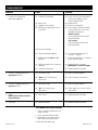
Da-Lite Contour Electrol Installation guide
- Category
- Projection screens
- Type
- Installation guide
This manual is also suitable for
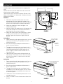
Da-Lite Contour Electrol is a versatile projection screen designed for various applications, including home theaters, conference rooms, and classrooms. It features a motorized operation for easy screen adjustment and retraction, allowing for flexible control of the screen's position. The screen's sturdy construction ensures durability and reliability, making it suitable for frequent use. With its sleek design and customizable installation options, the Da-Lite Contour Electrol offers a professional and convenient solution for projecting presentations, movies, and other visual content.
Da-Lite Contour Electrol is a versatile projection screen designed for various applications, including home theaters, conference rooms, and classrooms. It features a motorized operation for easy screen adjustment and retraction, allowing for flexible control of the screen's position. The screen's sturdy construction ensures durability and reliability, making it suitable for frequent use. With its sleek design and customizable installation options, the Da-Lite Contour Electrol offers a professional and convenient solution for projecting presentations, movies, and other visual content.


-
 1
1
-
 2
2
-
 3
3
-
 4
4
-
 5
5
-
 6
6
-
 7
7
-
 8
8


Da-Lite Contour Electrol Installation guide
- Category
- Projection screens
- Type
- Installation guide
- This manual is also suitable for
Da-Lite Contour Electrol is a versatile projection screen designed for various applications, including home theaters, conference rooms, and classrooms. It features a motorized operation for easy screen adjustment and retraction, allowing for flexible control of the screen's position. The screen's sturdy construction ensures durability and reliability, making it suitable for frequent use. With its sleek design and customizable installation options, the Da-Lite Contour Electrol offers a professional and convenient solution for projecting presentations, movies, and other visual content.
Ask a question and I''ll find the answer in the document
Finding information in a document is now easier with AI
Related papers
-
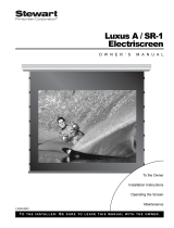
Da-Lite TENSIONED CONTOUR ELECTROL Owner's manual
-
Da-Lite ADVANTAGE ELECTROL User manual
-
Da-Lite Tensioned Advantage Electrol 69" x 110" User manual
-
-
-
-
Da-Lite 88538LS Installation guide
-
-
Da-Lite 85398LS User manual
-
Other documents
-
Projecta Tabscreen Electrol, High Contrast Cinema Vision Installation guide
-
Draper 121171 Datasheet
-
SNAP Dragonfly DFM-NTT Owner's manual
-
-
 Stewart Filmscreen Corp C User manual
-
-
-
-
 Stewart Filmscreen Corp LCD Front Projector User manual
-

