3
Installation
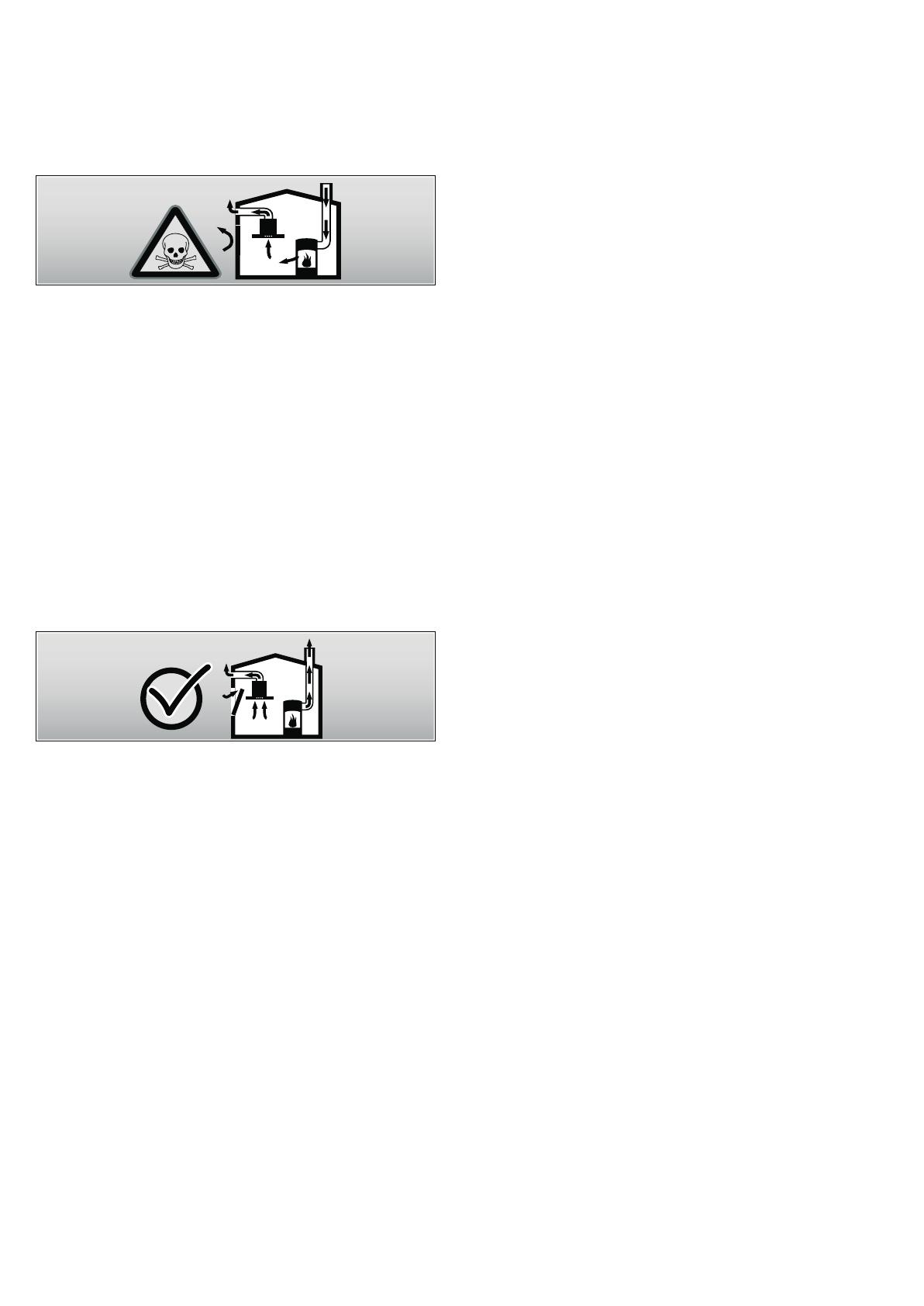
Mortal danger, risk of intoxication!
Due to combustion gases sucked back in. Never operate the
appliance in the exhaust air mode at the same time as a room
air-dependent heat-producing appliance unless an adequate
supply of fresh air is ensured.
Room air-dependent heat-producing appliances (e.g. gas, oil,
wood or coal-operated heaters, continuous flow heaters or
water heaters) obtain combustion air from the room in which
they are installed and discharge the exhaust gases into the
open through an exhaust gas system (e.g. a chimney).
In combination with an activated vapour extractor hood, room
air is extracted from the kitchen and neighbouring rooms - a
partial vacuum is produced if not enough fresh air is supplied.
Toxic gases from the chimney or the extraction shaft are
sucked backed into the living space.
■ Adequate incoming air must therefore always be ensured.
■ An incoming/exhaust air wall box alone will not ensure
compliance with the limit.
Safe operation is possible only whenever the partial vacuum in
the place where the firing equipment is installed does not
exceed 4 Pa (0.04 mbar). This can be achieved whenever the
air needed for combustion is able to enter through openings
that cannot be sealed, for example in doors, windows,
incoming/exhaust air wall boxes or by other technical means.
In any case, consult your responsible chimney sweep. He is
able to assess the house's entire ventilation setup and will
suggest the suitable ventilation measures to you.
Unrestricted operation is possible if the vapour extractor hood
is operated exclusively in the recirculation mode.
Risk of fire!
from flying sparks. Do not install appliance above a solid fuel
heater (e.g. wood or coal) unless a closed, non-removable
cover is available.
Caution!
Risk of damage from heat accumulation due to too narrow gap
between appliance and high-sided unit or wall. Only one side
of the appliance may be installed directly next to a high-sided
unit or a wall. Distance between the appliance and wall or high-
sided unit must be at least 50 mm.
The specified safety distances must be observed. Also observe
the specifications for your cooking appliance. If gas
and electric hobs are operated together, the largest specified
distance applies.
The width of the extractor hood must correspond at least
with the width of the hob.
For the installation observe the currently valid building
regulations and the regulations of the local electricity and gas
suppliers.
Risk of electric shock!
from damaged connection cable. Do not kink or pinch
connection cable during installation.
Risk of fire, risk of injury!
from damaged connection cable. A damaged connection cable
must be replaced by a qualified technician (electrician).
Risk of injury!
From sharp edges during installation. Always wear protective
gloves while installing the appliance.
Risk of injury!
from a falling appliance. All safety screws and safety caps must
be firmly fitted.
Using the appliance
Risk of burns!
from hot appliance when used with cooking appliances. Keep
children away and ensure appliance is used properly.
Risk of injury, risk of damage!
from objects falling on the appliance. Never place objects
on the appliance.
Risk of fire, risk of burns!
if gas hotplates not covered with cooking utensils. Always
use gas hotplates with appropriate cooking utensils. Regulate
flame to ensure that it does not lick over the cooking utensil.
Risk of burns, risk of damage!
if several gas hotplates are operated simultaneously. Never
operate two gas hotplates simultaneously on the highest flame
for longer than 15 minutes. The housing will become very hot
due to the intense heat.
Note: One large burner of more than 5 kW (Wok) is equivalent
to the power of two gas burners.
Risk of fire!
■ from grease deposits in the metal-mesh grease filter. Never
work under the appliance with a naked flame
(e.g. flambéing). Always operate appliance with metal-mesh
grease filter. Regularly clean the metal-mesh grease filter.
■ from overheated fats and oils. Heat fats and oils under
constant supervision only. Never extinguish fire with water,
always use a fire blanket, lid or plate.
Caution!
Risk of damage due to corrosion. Always switch on the
appliance while cooking to avoid condensation. Condensate
can produce corrosion damage.
Risk of injury!
due to LED lights of risk group 1. Do not look directly into the
switched on LED lights for longer than 100 seconds.


