Jackson / Dalton Dishwasher R30 Operating instructions
- Category
- Dishwashers
- Type
- Operating instructions
This manual is also suitable for
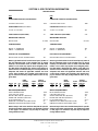
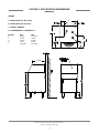
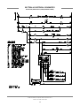
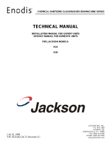
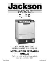
Jackson / Dalton Dishwasher R30 is a commercial-grade dishwasher designed for fast and efficient cleaning of glasses. With a capacity of 1800 glasses per hour, it's ideal for busy bars, restaurants, and other foodservice establishments. Its 120-second operating cycle and 3-gallon tank capacity ensure quick and thorough cleaning. The R30 is equipped with a 55 GPM wash pump, ensuring powerful and effective cleaning. Its 208-230 Volt, 60 Hertz, Single Phase electrical requirements make it compatible with most commercial electrical systems.
Jackson / Dalton Dishwasher R30 is a commercial-grade dishwasher designed for fast and efficient cleaning of glasses. With a capacity of 1800 glasses per hour, it's ideal for busy bars, restaurants, and other foodservice establishments. Its 120-second operating cycle and 3-gallon tank capacity ensure quick and thorough cleaning. The R30 is equipped with a 55 GPM wash pump, ensuring powerful and effective cleaning. Its 208-230 Volt, 60 Hertz, Single Phase electrical requirements make it compatible with most commercial electrical systems.


-
 1
1
-
 2
2
-
 3
3
-
 4
4
-
 5
5
-
 6
6
-
 7
7
-
 8
8
-
 9
9
-
 10
10
-
 11
11
-
 12
12
-
 13
13
-
 14
14
-
 15
15
-
 16
16
-
 17
17
-
 18
18
-
 19
19
-
 20
20
-
 21
21
-
 22
22
-
 23
23
-
 24
24
-
 25
25
-
 26
26
-
 27
27


Jackson / Dalton Dishwasher R30 Operating instructions
- Category
- Dishwashers
- Type
- Operating instructions
- This manual is also suitable for
Jackson / Dalton Dishwasher R30 is a commercial-grade dishwasher designed for fast and efficient cleaning of glasses. With a capacity of 1800 glasses per hour, it's ideal for busy bars, restaurants, and other foodservice establishments. Its 120-second operating cycle and 3-gallon tank capacity ensure quick and thorough cleaning. The R30 is equipped with a 55 GPM wash pump, ensuring powerful and effective cleaning. Its 208-230 Volt, 60 Hertz, Single Phase electrical requirements make it compatible with most commercial electrical systems.
Ask a question and I''ll find the answer in the document
Finding information in a document is now easier with AI
Related papers
-
 Jackson / Dalton Dishwasher R30 User manual
-
 Jackson / Dalton Dishwasher CJ-14 User manual
-
Jackson / Dalton Dishwasher CJ-16 User manual
-
 Jackson / Dalton Dishwasher CJ-20 User manual
-
 Jackson / Dalton Dishwasher CJ-20 User manual
-
 Jackson / Dalton Dishwasher JP-24B-460 User manual
-
 Jackson / Dalton Dishwasher JP-24B-208/230 User manual
-
 Jackson / Dalton Dishwasher JP-24B-460 User manual
-
 Jackson / Dalton Dishwasher ConserverXL User manual
-
 Jackson / Dalton Dishwasher JP-24BPNSU-460 User manual


Other documents
-
Jackson JP-24BPNSU User manual
-
Delta Delta 1200 Installation guide
-
-
-
-
-
-
-
-
Champion CGM7-2 Installation guide