Page is loading ...

Danfoss scroll for refrigeration
LGWP MLZ/LLZ Evolution A (with
POE Oil) for parallel applications
50 - 60 Hz - R404A, R134a, R22, R507, R407A, R407F, R448A, R449A, R452A
Application guidelines
http://cc.danfoss.com


Content
3FRCC.PC.054.A1.02
General overview ................................................................................................................................. 4
Scope ............................................................................................................................................................................................................... 4
Benets ........................................................................................................................................................................................................... 4
Oil management concept .................................................................................................................... 5
Active systems.............................................................................................................................................................................................. 5
Passive systems ............................................................................................................................................................................................ 6
Operating conditions .......................................................................................................................... 8
Power supply ................................................................................................................................................................................................ 8
Compressor ambient temperature ...................................................................................................................................................... 8
Operating envelope ................................................................................................................................................................................... 8
Refrigerants and lubricants ..................................................................................................................................................................... 8
Discharge temperature protection ...................................................................................................................................................... 9
High and low pressure protection ....................................................................................................................................................... 9
Cycle rate limit .............................................................................................................................................................................................. 9
System design recommendations .................................................................................................... 10
Essential piping design considerations ............................................................................................................................................ 10
Expansion device ...................................................................................................................................................................................... 11
Suction accumulator................................................................................................................................................................................11
Suction header ...........................................................................................................................................................................................11
Oil level regulator .....................................................................................................................................................................................12
Technical features of oil level regulator tested in our laboratories ....................................................................................... 12
Oil separator / Oil reservoir ...................................................................................................................................................................13
Oil Separator (OS) ......................................................................................................................................................................................13
Oil separator / Oil reservoir for active system ................................................................................................................................14
Refrigerant charge limits........................................................................................................................................................................16
Installation and service ..................................................................................................................... 17
Piping design ..............................................................................................................................................................................................17
Wiring and rotation direction ..............................................................................................................................................................17
Failure analysis ........................................................................................................................................................................................... 17
Ordering information ........................................................................................................................ 18
Parallel units of MLZ and LLZ ............................................................................................................ 19
Composition of MLZ and LLZ uneven tandem/trio/quadro ....................................................................................................19
Composition of MLZ and LLZ even tandem ................................................................................................................................... 19
Compressor mounting ............................................................................................................................................................................21
Oil equalisation connection..................................................................................................................................................................21
Application Guidelines

General overview
The application guidelines describe the operating
characteristics, design features and application
requirements for MLZ/LLZ parallel compressors in
low temperature refrigeration applications.
To ensure proper parallel installation and running
conditions, the following recommendations must
be followed:
• It is essential to follow all the instructions
given in these guidelines, the instruction
leaet delivered with each compressor and the
Selection & Application Guidelines for single
compressors.
• For additional system components related to
specic application requirements, the supplier's
recommendations must always be followed.
Parallel compressor installation' refers to a system
of interconnected compressors with a common
suction line and common discharge line. The
technique of mounting compressors in parallel
is also referred to as manifolding. In a system
with only two compressors, this is referred to as a
tandem conguration.
The main reason for parallel compressor is
reduced operating cost through greater control
of capacity and power consumption. This is
achieved by staggering the compressor switch-
on sequences that allow the parallel system to
match its power with the capacity needed.
A second reason for parallel compressor is
improved part load eciency. In a parallel
installation the individual compressor(s) can be
switched o while the other compressor(s) keep
operating at 100% load. Therefore the part load
eciency is very near the full load eciency.
Conventional xed-speed compressor unloading
methods impose a serious penalty on part load
eciency, mainly at low load conditions.
Scope
Benets
4 FRCC.PC.054.A1.02
Application Guidelines

Oil management concept
Suction gas in a hermetic scroll compressor
ows via the oil sump,which makes it more
dicult to maintain equal pressure in the sumps
of parallel compressors. Since oil equalisation
usually depends on equal sump pressures, this is
a point of special attention. Danfoss Commercial
Compressors have developed specially adapted
oil management systems which ensure proper
oil balancing between the compressors, but it is
always recommended to carry out some tests to
validate oil balancing in the system.
To ensure suitable oil distribution, both passive
and active types of systems are introduced into
MLZ/LLZ compressors.
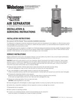
Active systems
An active system can oer more exible
and ecient oil management. It is highly
recommended for manifolding since this
positive system increases the reliability of the
manifolding conguration. Oil management
will be secured mainly by the oil level regulator
and the oil separator, which can supply the
oil when required. The active system can thus
accommodate itself to various oil conditions.
Danfoss has qualied tandem / trio / quadro
composition for active systems.
For manifolding with more than two
compressors, it is always suggested to use a
suction header. Each compressor will equip
the oil level regulator to facilitate the oil level
balance.
To avoid refrigerant back ow from high pressure,
it is always recommended to have a non-return
valve on the discharge line of each compressor,
as well as one non-return valve on the outlet
of the oil separator in the system to prevent
refrigerant migration.
For more details on the oil separator/reservoir
and oil level regulator please refer to the “System
design recommendation” in this guideline.
High pressure
Low pressure
Non return
valve
Suction
header
Non return
valve
Non return
valve
Non return
valve
Combined oil
separator/reservoir
Oil lter
Non return
valve
Compressor 1
Oil level regulator Oil level regulator Oil level regulator Oil level regulator
Compressor 2 Compressor 3 Compressor 4
5FRCC.PC.054.A1.02
Application Guidelines

Oil management concept
Passive systems
Compressor 1 Compressor 2
Suction header
From evaporator
To condenser
Oil equalization
line
Non return valve
Non return valve
Oil separator with
oating-ball valve
Oil lter
A passive system is an oil management system
without any measurement or control devices
such as oil level regulators and oil controllers.
By contrast, a solution equipped with such
measurement or control devices is called an
active system.
Danfoss has qualied only the even tandem
(two same compressors) for passive solutions.
6 FRCC.PC.054.A1.02
Application Guidelines

Oil management concept
This is one of the simplest and cheapest ways of
manifolding compressors. It is very popular in air-
conditioning applications, but in refrigeration this
kind of system needs to be paid special attention
due to severe operating conditions.
Danfoss has qualied only the even tandem
(two same compressors) for passive solutions.
Compressor sumps and low-pressure shells are
interconnected. An interconnecting pipe on the
lower part of the compressor (installed on the
existing oil sight glass) ensures oil balancing.
The suction header design is critical, as it
ensures a pressure drop balancing and an equal
distribution of oil returning from the system
when both compressors are running.
The success of such a system relies very much
on the sizing and design of the pipe work, as
small dierences in sump pressure can result in
signicant oil level variations. This system needs
perfect suction tube balancing.
For an LLZ even tandem, oil return can be
secured by an oil separator with oat ball valve,
which will return the oil to the main suction
line. The oil equalisation line goes through the
oil sight glass with an adaptor on the standard
compressor. To avoid refrigerant back ow from
high pressure, it is always recommended to have
a non-return valve on the discharge line of each
compressor, as well as one non-return valve on
the outlet of the oil separator in the system to
prevent refrigerant migration.
The following are recommendations from
Danfoss application engineering for connecting
low temperature compressors using an oil
equalisation line system without active control:
• An adequately (generously) sized suction
header is needed to provide for equal
distribution of returning refrigerant gas and oil
to each individual compressor; also the suction
header should be installed horizontally.
• To secure sucient oil return to the compressor,
Danfoss suggests below dimension requirement
of the suction header: H>5D.
Height
Main suction
line
D
• The oil equalization tube is recommended to
have an outer diameter of ½’’.
• If the unit runs in a very cold situation, both
compressors need to be switched on after a
period of single running for better oil circulation,
especially in low load conditions.
• Care must be taken to mount all the
compressors on the same horizontal level and
also to provide adequate liquid ood back
protection when using this method.
Danfoss could provide piping drawings for even
tandem passive system, please contact Danfoss
for more information.
7FRCC.PC.054.A1.02
Application Guidelines

Operating conditions
MLZ and LLZ compressors can be operated at
nominal voltages as indicated below. Under-
voltage and over-voltage operation is allowed
within the indicated voltage ranges. In case of
risk of undervoltage operation, special attention
must be paid to current draw.
The recommended parallel assemblies design
from Danfoss Commercial Compressors have
been qualied to ensure there is no impact on
the compressor operating envelope.
More details can be found in the “MLZ and LLZ
application guidelines”.
Power supply
Compressor ambient
temperature
Operating envelope
Refrigerants and
lubricants
MLZ/LLZ scroll compressors can be applied
from -35°C to 55°C ambient temperature. The
compressors are designed as 100% suction
gas cooled without the need for additional fan
cooling.
Ambient temperature has very little eect on the
compressor performance.
Approved refrigerants and lubricants for MLZ
and LLZ single compressors are also allowed for
parallel assemblies. For more details, please refer
to the "MLZ and LLZ application guidelines".
Motor voltage
code 2
Motor voltage
code 4
Motor voltage
code 7
Motor voltage
code 9
Nominal voltage 50 Hz 200-220 V - 3 ph 380-415 V - 3 ph - -
Voltage range 50 Hz 180 - 242 V 342 - 456 V - -
Nominal voltage 60 Hz 208-230 V - 3 ph 460 V - 3 ph 575 V - 3 ph 380 V - 3 ph
Voltage range 60 Hz 187 - 253 V 414 - 506 V 517 - 632 V 342 - 418 V
MLZ scroll compressors are available in 6 dierent motor voltages.
Motor voltage
code 1
Motor voltage
code 2
Motor voltage
code 4
Motor voltage
code 5
Motor voltage
code 7
Motor voltage
code 9
Nominal voltage
50 Hz
- 200-220 V - 3 ph 380-415 V - 3 ph 220-240 V - 1 ph - -
Voltage range
50 Hz
- 180 - 242 V 342 - 457 V 198 - 264 V - -
Nominal voltage
60 Hz
208-230 V - 1 ph 208-230 V - 3 ph 460 V - 3 ph - 575 V - 3 ph 380 V - 3 ph
Voltage range
60 Hz
187 - 253 V 187 - 253 V 414 - 506 V - 517 - 632 V 342 - 418 V
LLZ scroll compressors are available in four dierent motor voltages.
8 FRCC.PC.054.A1.02
Application Guidelines

Discharge temperature
protection
The discharge gas temperature of each
compressor must not exceed 135°C.
DGT protection is required if the high and
low-pressure switch settings do not protect
the compressor against operations beyond its
specic application envelope.
More details can be found in the “MLZ and LLZ
application guidelines”.
The pump-down pressure switch must have a set
point slightly higher than the lowest compressor
safety pressure switch set point. The compressor
switch must never be bypassed and shall stop
all the compressors. The high-pressure safety
pressure switch shall stop all the compressors.
Whenever possible (i.e. PLC control) it is
recommended to limit the possibility of
compressor auto-restart caused by LP safety
switch settings to fewer than 3 to 5 times during
a 12-hour period.
Please refer to the “MLZ and LLZ application
guidelines” for recommended settings.
High and low pressure
protection
Cycle rate limit The system must be designed in a way that
guarantees a minimum compressor running time
of two minutes so as to provide for sucient
motor cooling after start-up along with proper oil
return. Note that the oil return may vary since it
depends upon system design.
There must be no more than 12 starts per hour (6
when a resistor soft-start accessory is introduced);
a number higher than 12 reduces the service life
of the motor-compressor unit. If necessary, place
an anti-short-cycle timer in the control circuit,
then connect as shown in the wiring diagram
in the Danfoss Scroll compressor application
guidelines. A three-minute (180-second) time-out
is recommended.
Danfoss recommends a restart delay timer to
limit compressor cycling.
9FRCC.PC.054.A1.02
Application Guidelines

System design recommendations
To ensure proper refrigerant and oil circulation,
the speed limits in all pipes are generally
recommended as follows:
• For horizontal/vertical discharge gas velocity: no
more than 15m/s;
• For vertical suction gas velocity: no less than
7.6m/s;
• For horizontal suction gas velocity: no less than
3.6m/s;
• For horizontal/vertical liquid velocity: around
1.5m/s;
• For suction header gas velocity: no more than
4m/s.
Essential piping design
considerations
Proper piping practices should be employed to
ensure adequate oil return, even under minimum
load conditions, with special consideration
given to the size and slope of the tubing coming
from the evaporator. Tubing returns from the
evaporator should be designed so as not to trap
oil and to prevent oil and refrigerant migration
back to the compressor during o-cycles.
If the evaporator lies above the compressor,
the addition of a pump-down cycle is strongly
recommended. If a pump-down cycle were to
be omitted, the suction line must have a loop at
the evaporator outlet to prevent refrigerant from
draining into the compressor during o-cycles.
If the evaporator is situated below the
compressor, the suction riser must be trapped to
ensure the oil return to the compressor (see g.1).
When the condenser is mounted at a higher
position than the compressor, a suitably sized
“U”-shaped trap close to the compressor is
necessary to prevent oil leaving the compressor
from draining back to the discharge side of the
compressor during o-cycle. The upper loop also
helps avoid condensed liquid refrigerant from
draining back to the compressor when stopped
(see g. 2). The maximum elevation dierence
between the indoor and outdoor section cannot
exceed 8 m. System manufacturers should specify
precautions for any applications that exceed
these limits to ensure compressor reliability.
Economiser heat exchanger piping shall be
arranged in a counter ow of gas and liquid to
assure optimum heat transfer and therefore best
subcooling eect.
Piping should be designed with adequate three-
dimensional exibility (gure 2). It should not
be in contact with the surrounding structure,
unless a proper tubing mount has been installed.
This protection proves necessary to avoid
excess vibration, which can ultimately result
in connection or tube failure due to fatigue
or wear from abrasion. Aside from tubing and
connection damage, excess vibration may be
transmitted to the surrounding structure and
generate an unacceptable sound level within that
structure as well (for more information on sound
and vibration, see the section on “Sound and
vibration management”).
HP
LP
>3.6 m/s
<15 m/s
0.5% >
max. 4 m
U-trap
>3.6m/s
Evaporator
>7.6 m/s
max. 4 m
HP
LP
Condenser
10 FRCC.PC.054.A1.02
Application Guidelines

System design recommendations
Expansion device When the parallel installation is serving a single
evaporator system, the dimensioning of the
expansion device (thermostatic or electronic)
becomes critical and must be made in relation
to both minimum and maximum capacity.
This will ensure correct superheat control in all
situations, with a minimum of 5K superheat at
the compressor suction. The expansion device
should be sized to ensure proper control of
the refrigerant ow into the evaporator. An
oversized valve may result in erratic control.
Proper selection could imply a slightly undersized
expansion valve at full load. This consideration
is especially important in manifolded units
where low load conditions may require the
frequent cycling of compressors. This can lead
to liquid refrigerant entering the compressor
if the expansion valve does not provide stable
refrigerant superheat control under varying
loads. The superheat setting of the expansion
device should be sucient to ensure proper
superheat levels during low loading periods.
A minimum of 5K stable superheat is required.
In addition, the refrigerant charge should be
sucient to ensure proper subcooling within the
condenser so as to avoid the risk of ashing in the
liquid line before the expansion device.
The refrigeration compressor is designed to
compress vapour only. A suction line accumulator
prevents compressor damage from a sudden
surge of liquid refrigerant and oil that could enter
the compressor from the suction line. For low
temperature application, suction accumulator
is a must unless approved by careful tests under
dierent operating conditions.
Selection of a suction line accumulator should
be made on the basis of the following three
capabilities:
1. The accumulator should have an adequate
liquid-holding capacity that can vary with the
system. Normally this should not be less than
50% of the system charge. If possible, this value
should be checked based on actual tests.
2. The accumulator should perform without
adding excessive pressure drop to the system.
3. An accumulator should have the capability of
returning oil at the proper rate and under a range
of load conditions.
Guideline of suction accumulator needs to be
respected in making a selection.
For ecient oil management in parallel systems
the oil should return to the compressor at
approximately the same rate as it leaves so
that an appropriate oil level can always be
maintained.
Danfoss recommends an adequately sized
suction header which provides equal distribution
of returning refrigerant and oil to each individual
compressor. The suction lines from the header
towards each individual compressor must be
tted into the suction header. This conguration
will result in a higher gas velocity at the pick-up
tube inlet and proper oil return when the oil
level in the suction header rises. The compressor
suction lines must always enter the suction
header on the topside. A recommended suction
header design is shown below.
Suction accumulator
Suction header
Suction gas
Suction gas to
compressor
11FRCC.PC.054.A1.02
Application Guidelines

System design recommendations
Oil level regulator
Oil level regulator monitors the oil level and
controls oil injection by switching the solenoid
valve on and o to maintain an acceptable oil
level in the compressor the crankcase. When
crankcase oil level cannot be restored within a
period of time (setting value), the alarm contactor
will be activated and stop the compressor to
protect it from damage (some oil level regulator
do not have an alarm function).
According to the function, there are three
types of oil level regulator: electronic,
electromechanical and mechanical. For a
high-pressure oil reservoir system, Danfoss
recommends individual electronic oil control
regulators over the mechanical oat ball oil
regulator system for eective oil regulation. For
the a low-pressure system, all types are allowed.
Danfoss has qualied the below oil level
regulators. Due to various operations in
refrigeration systems, the customer needs to
verify the conguration specied for their own
solutions.
• TEKLAB:
TK3-DANF-R01: Danfoss recommends this kind
of Oil level regulator for its overall quality. It can
judge the oil level precisely even when there is
some oil foaming. The total time before the alarm
is four minutes with the new control module,
which is suitable for LLZ compressors. The
adaptor of TEKLAB perfectly matches the oil sight
glass tting of LLZ compressor. A lter is needed
before Oil level regulator.
• Henry AC&R:
OP-02: The action and control logic works well
with LLZ compressors, while adaptors can t, but
not very well, with the oil sight glass tting. A
lter is needed before oil level regulator.
Note: Customers must refer to the manufacturer's
guidelines on oil level regulators for proper set-
up and operation.
To ensure ideal pressure equalization, the suction
header must be symmetrical and the lines from
the suction header to each compressor must be
short and identical. These recommendations are
not so critical when using an active system.
Danfoss recommends the following as necessary
for secure a suction header installation:
• The suction header should be adequately sized
for equal distribution of returning refrigerant gas
and oil to each individual compressor; also the
suction header should be installed horizontally.
• The gas velocity in the suction header must be a
maximum of 4 m/s.
• The suction line and the suction header must be
insulated to limit suction gas superheat.
Technical features of oil level regulator
tested in our laboratories
Items
Teklab
TK3-DANF-R01
AC&R
OP-02
Alco
OM3
Alco
OM4
Alco OMB
Fasike
FOE
Type Electronic Electronic Electronic Electronic Electronic
Mechanical-
electronic
Solenoid control Optical sensor Optical sensor Optical sensor Optical sensor Optical sensor Reed-switch
Power supply 24 VAC, 50/60 Hz 24 VAC, 50/60 Hz
24 VAC,
50/60 Hz
24 VAC,
50/60 Hz
24 VAC,
50/60 Hz
220 VAC,
50 Hz
Output signal 230VAC/3A
24V DC/2A or120V
AC/2A
230V AC/3A 230V AC/3A 230V AC/3A 230V AC/3A
Function
Oil feeding
Alarming/cut o
Oil feeding
Alarming/cut o
Oil feeding
Alarming/cut o
Oil feeding
Alarming/cut o
Oil feeding
Alarming/cut o
Oil feeding
Alarming/cut o
Max working
pressure
45bar 35bar 31bar 45bar, for CO2/R410A
34.5bar
(500psi)
29bar
Max working
temperature
85°C 80°C 80°C 80°C
82°C
(180°C)
120°C
Oil lling time
before alarming
240s 120s
20s after Oil level is
below 25% OSG.
20s after Oil level is
below 25% OSG.
110s N/A
12 FRCC.PC.054.A1.02
Application Guidelines

System design recommendations
Oil separator / Oil
reservoir
Oil Separator (OS) There are dierent types of oil separators in the market.
Impingement (Filter) type OS: Traditionally,
this type of OS is widely used in the market; the
maximum eciency is around 80%. They use
inlet and outlet metal web to interrupt the oil
particles and force them collide with each other,
eventually heavier oil particle is formed and drips
down to the bottom of OS by gravity. The feature
of this type OS is the eciency goes up with the
gas velocity drops down. For
this type of OS, there is option
with/without oat ball valve.
According to marketing’s
requirement, Hono, AC&R,
ALCO OSs are in the scope of
the test plan.
Filter-demister type OS: This type of OS is with
a lter cartridge at the end of inlet, sometimes,
there are some metallic stu inside the lter
cartridge which has demister function, such
as Fasike and Frigomec. The oil separation
eciency is higher than the previous one. Fasike
& Frigomec OS is in the scope of our test plan.
For passive solution, the OS is selected with
oat ball valve to assure
there is no gas bypass to
compressor oil sump; for
active solution with high
pressure oil management
system, it is without oat
ball valve, but with oil
reservoir function.
Coalescing type OS: Properly designed
coalescing separators can remove 95%-99% of
the oil component of mass ow. They use a lter
media of highly pure glass bbers, capable of
intercepting even the smallest oil molecules.
This material forces the molecules to collide and
form larger droplets, which in turn are routed by
gravity through a drain layer. With this type of OS,
after a period of running, the coalescent cartridge
will be saturated and
the separation eciency
would drop sharply. And
the cost of this type of
OS is very high. We didn’t
qualify this type of OS in
our project scope.
Centrifugal type OS: The oil contained in the
refrigerant gas collides with the helix guide
plate and then ows along the guide plate.
The oil particles are separated onto the edge of
the helix guide plate and the shell wall by the
centrifugal force. The separated oil particles get
together and become heavier ones and then drip
to the bottom of the OS. For this type of OS, the
eciency can reach to maximum 95%-99%. The
feature of the OS is the eciency drops down
with the gas velocity drops down. There is option
with/without oat ball
valve inside the OS. For
passive solution, Carly
centrifugal OS with oat
ball valve is selected to be
test; for active solution,
Carly OS and Fasike OS
without oat ball valve are
selected to be test.
13FRCC.PC.054.A1.02
Application Guidelines

Active system
Oil separator / Oil
reservoir for active
system
Passive system
When an active system is adopted by the
customer, the oil separator is always considered
together with oil reservoir.
Due to system design, loads and defrost cycles,
etc, there will be varying amounts of oil returning
to the oil separator. Because of this, a safety
reserve of oil is required for successful operation
of the active system.
Oil separator for passive
system
The role of the oil separator is to intercept the
mixed oil from the compressed refrigerant gas
and returns it back to the compressor to assure
ecient lubrication of its moving parts, and
also to improve the system heat exchangers’
eciency. In our manifolding system, the oil
separator is installed in the compressor discharge
line as shown below.
No oil separator category is included in this
guidelines. For more details, please refer to the
manufacture’s guidelines.
Regarding passive solutions, it is recommended
to use an oil separator with a oating-ball
valve. The oating-ball valve can control the
oil ow and act as a capillary in the oil return
line; therefore, there is no need to install an oil
capillary in the system.
Compressor 1 Compressor 2
Suction header
From evaporator
To condenser
Oil equalization
line
Non return valve
Non return valve
Oil separator with
oating-ball valve
Oil lter
High pressure
Low pressure
Non return
valve
Suction
header
Non return
valve
Non return
valve
Non return
valve
Combined oil
separator/reservoir
Oil lter
Non return
valve
Compressor 1
Oil level regulator Oil level regulator Oil level regulator Oil level regulator
Compressor 2 Compressor 3 Compressor 4
System design recommendations
14 FRCC.PC.054.A1.02
Application Guidelines

System design recommendations
High pressure oil reservoir (combined oil
separator/oil reservoir)
Danfoss recommends that high-pressure systems
are congured in active solutions. These systems
store the oil in a common oil separator / reservoir
at compressor discharge pressure (see the gure
below). The advantage is that these systems
do not need a separated oil reservoir but make
use of a combined oil separator / reservoir
arrangement ,which normally results in a cost
saving over traditional low-pressure systems.
From an application point of view, high-pressure
systems are more critical than traditional low
pressure systems and care must be taken to
make sure that the separator / reservoir installed
is of sucient size and oil content (as per
manufacturer’s recommendation) so that there
is always oil stored. And pay special attention to
avoid discharge gas entering the compressor oil
sump, which could lead to some negative eects
such as higher discharge and oil temperatures,
less lubrication capability and the loss of
eciency due to hot-gas bypass.
Active solution with high pressure oil reservoir (combined oil separator/oil reservoir)
Low pressure oil reservoir with separate oil
separator
Usage of an oil reservoir is very common in low-
pressure systems to control the variations in oil
quantity during operation (see below). In this
conguration, the oil reservoir is maintained at a
pressure slightly above the compressor suction
pressure using a dierential pressure valve (check
valve). Therefore, the amount of refrigerant
dissolved in the oil will be limited. The pressure
drop is low when the oil enters the compressor
and the amount of ash gas formed in the sump
is small. The dierential pressure required for
sucient oil ow from the oil reservoir to the
compressor is system specic, depending upon
the application and components chosen.
Active solution with low pressure oil reservoir
Oil filter
Common suction header
Oil separator/Oil
reservoir
To condenser
From evaporator
To condenser
From evaporator
Oil separator with
float ball valve
Oil reservoir
Oil filter
Differential pressure
Check valve
Common suction header
15FRCC.PC.054.A1.02
Application Guidelines

System design recommendations
In brief, oil separator and oil reservoir are always
considered together regarding active system.
For active solution with high pressure oil reservoir
system it is recommended to use oil separator(no
oat ball valve) with oil stored function. In
other words, a combined oil separator/oil
reservoir. For low pressure oil reservoir system,
it is recommended to work together with oil
separator which with oat ball valve.
Generally Danfoss recommend to use high
pressure oil reservoir system (one oil seperator
with oil reserve function).
Passive solution
Active solution
Refrigerant charge limits
If refrigerant charge exceeds the limit, a liquid receiver and suction accumulator will be essential to
ensure that the system runs reliably.
Compressor models
CHARGE LIMIT-for parallel Compressors
Tandem Trio Quadro
LLZ013-015 5.9 7.7 10
LLZ024-034 9.4 12.3 16
MLZ015-026 4.7 6.1 7.9
MLZ030-048 7 9.1 11.9
MLZ058-076 9.4 12.2 15.8
Danfoss has qualied the below oil separator.
Due to various applications in refrigeration
systems, the customer needs to verify the
conguration specied for their own solutions.
Please refer to oil separator's guideline for more
information.
Country* CN NAM/CN NAM/CN EMA EMA EMA
Company Fasike O&F Emerson ALCO Henry AC&R Frigomec Frigomec Carly
Model F-65 A-WE S-CE SO/ERS SO/ER Turboil-F for PVE oil
Type Filter Impingement Impingement Filter Filter-demister Centrifugal
Note*: The countries listed here only indicate whether the product is available in local country or not for now. Regardless the
availability, all the OS above has been qualied by Danfoss under certain conguration.
Country* CN EMA EMA
Company Fasike O&F Frigomec Carly
Model F-66Q SRO/ERS Turboil-R for PVE oil
Type Centrifugal Oil-stored Filter Oil-stored Centrifugal Oil-stored
Note*: The countries listed here only indicate whether the product is available in local country or not for now. Regardless the availa-
bility, all the OS above has been qualied by Danfoss under certain conguration.
16 FRCC.PC.054.A1.02
Application Guidelines

Installation and service
Piping design
Wiring and rotation
direction
Failure analysis
Due to the various MLZ/LLZ parallel
congurations, Danfoss only provides an even
tandem piping design. For uneven, trio and
quadro active systems, the customer can make
their own design based on the velocity limits.
For each tandem conguration specic outline
drawings are available as indicated on the
following pages. These drawings must always be
followed.
No changes shall be made to the indicated
tubing diameter and tting types. As for passive
systems, the oil equalisation line shall be made of
copper tube and assembled in such a way so that
it does not extend above the connection height
and must be horizontal so as not to trap oil.
Please contact Danfoss Sales for specic
drawings.
All compressors in a tandem unit must be
electrically wired individually.
Compressors should run with the correct rotation
direction. This can be achieved by having the
correct phase sequence on each compressor
motor terminal (L1-T1, L2-T2, L3-T3).
When one compressor in a parallel system fails,
the chance of foreign particles entering other
compressors is greatly increased. Therefore a
failure analysis must be done quickly to ensure
further proper running conditions for the overall
installation (i.e.: oil analysis).
17FRCC.PC.054.A1.02
Application Guidelines

Ordering information
To build a complete tandem, one must order
two compressors and the tandem kit. Danfoss
MLZ/LLZ compressors can be ordered in either
industrial packs or in single packs. Please refer to
the single compressor application guidelines for
ordering.
All MLZ/LLZ tandem conguration will share the
same tandem kit.
Kit code number 120Z5073
Designation Qty
1 Flat washer 8
2 Spacer 8
3 Rotolock sleeve 2
4 Rotolock nut 2
5 Adaptor 2
6 O-ring 2
7 Teon seal 2
18 FRCC.PC.054.A1.02
Application Guidelines

Parallel units of MLZ and LLZ
Composition of MLZ and
LLZ uneven tandem/trio/
quadro
Composition of MLZ and
LLZ even tandem
These compositions can only work with active
systems.
Danfoss will not provide drawings for these
congurations. Pipe sizes can be calculated based
on the velocity the limits in “Essential piping
design" section. And Customers need to do their
own validation.
Active system
Active system
Brazed version
Rotolock version
Tandem model A (OD) B (OD) C (OD) D (ID)
MLZ015-026 1/2" 3/4" 1" 3/4"
MLZ030-045 1/2" 7/8" 1-1/8" 7/8"
MLZ048 3/4" 7/8" 1-1/8" 1-1/8"
MLZ058-076 7/8" 1-1/8" 1-3/8" 1-1/8"
Tandem model A (OD) B (OD) C (OD) D (ID)
MLZ015-026 1/2" 3/4" 1" 3/4"
MLZ030-045 1/2" 3/4" 1-1/8" 7/8"
MLZ048 3/4" 3/4" 1-1/8" 1-1/8"
MLZ058-076 3/4" 1-1/8" 1-3/8" 1-1/8"
LLZ013-018 1/2" 3/4" 1-1/8" 7/8"
LLZ024-034 3/4" 1-1/8" 1-3/8" 1-1/8"
19FRCC.PC.054.A1.02
Application Guidelines

Parallel units of MLZ and LLZ
Passive system
Passive system
Brazed version
Rotolock version
Tandem model A (OD) B (OD) C (OD) D (OD) E (OD) F (ID)
MLZ015-026 1/2" 3/4" 1/2" 1" 1-5/8" 3/4"
MLZ030-045 1/2" 7/8" 1/2" 1-1/8" 64mm 7/8"
MLZ048 3/4" 7/8" 1/2" 1-1/8" 64mm 1-1/8"
MLZ058-076 7/8" 1-1/8" 1/2" 1-3/8" 3" 1-1/8"
Tandem model A (OD) B (OD) C (OD) D (OD) E (OD) F (ID)
MLZ015-026 1/2" 3/4" 1/2" 1" 1-5/8" 3/4"
MLZ030-045 1/2" 3/4" 1/2" 1-1/8" 64mm 7/8"
MLZ048 3/4" 3/4" 1/2" 1-1/8" 64mm 1-1/8"
MLZ058-076 3/4" 1-1/8" 1/2" 1-3/8" 3" 1-1/8"
LLZ013-018 1/2" 3/4" 1/2" 1-1/8" 64mm 7/8"
LLZ024-034 3/4" 1-1/8" 1/2" 1-3/8" 3-1/8' 1-1/8"
20 FRCC.PC.054.A1.02
Application Guidelines
/