
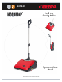
1
Small Area
Cleaning Machine
E84700-00
Operator and Parts
Manual
MOTOMOP
™
400 Van Camp Road • Bowling Green, Ohio 43402
Customer Service: 888-GO-BETCO • Fax: 800-445-5056 • Technical Service: 877-856-5954 • www.betco.com

2
TABLE OF CONTENTS
RECEIVING THE MACHINE ............................................ 3
TECHNICAL INFORMATION............................................ 4
GENERAL SAFETY INFORMATION ................................ 5
MACHINE PREPARATION .........................................6 - 9
OPERATION ................................................................. 10
AFTER OPERATION ...................................................... 11
MAINTENANCE .....................................................12 - 14
DISPOSAL .................................................................... 15
MACHINE DIAGRAM AND PARTS LISTING ..........16 - 35
WARRANTY ................................................................. 36

3
Immediately check, when receiving the machine, that all the materials indicated on delivery documents have been received and
also that the machine has not been damaged in transit. If it has been damaged, this damage must be immediately reported to
the shipper and also to our customer’s service department or a claim may not be made.
INTRODUCTION
This is an automatic scrubber which, via the mechanical ac-
tion of the rotating brush and the chemical action of a water/
detergent solution, cleans all types of hard flooring. As the
scrubber advances, it also collects the dirt removed and the
detergent solution not absorbed by the floor.
Only use this machine for its intended purpose. Please keep
the machine in good working order by preforming routine
maintenance. Read this instruction manual and refer back
to it when machine questions arise. Our technical customer
service representatives should be contacted when machine
questions are not answered by this manual.
RECEIVING THE MACHINE
SYMBOLS USED ON THE MACHINE
Serial # Plate

4
Working width in 13.5
Rear squeegee width in 16
Work capacity ft
2
/hr 7,320
Battery - Lithium-ion
Run time - Up to 1 hour
Brush diameter in 4.3
Brush motor W 50
Drive type - Brush Assisted
Maximum grade - 2%
Vacuum motor W 100
Solution tank capacity Gal 1/3 gallon
Recovery tank capacity Gal 1/3 gallon
Weight of empty machine (without battery) lbs 19.8
Weight of empty machine (with battery) lbs 22.0
Machine dimensions upright (Length/Height/Width) in x in x in 17.5 x 51.0 x 15.9
Machine dimensions stored (Length/Height/Width) in x in x in 14.4 x 36.0 x 15.9
TECHNICAL DESCRIPTION Measurement Unit MotoMop
™

5
The guidelines below must be carefully followed in order to avoid harm to the operator and damage to the machine.
• Read the labels on the machine carefully. Do not cover the labels and replace them if they become damaged.
• The machine must be used only by authorized and trained personnel.
• When operating the machine do not endanger other people.
• The machine is not suitable for cleaning carpets.
• The charger power cord must be plugged into a grounded power outlet.
• Avoid damaging the power cable by not crushing, bending, cutting or stressing it.
• WARNING: Do not let the power cable come into contact with the rotating brush.
• Whenever the power cable is damaged, immediately contact a BETCO service center for a replacement power cord.
• Do not mix different types of detergent as they may produce harmful gases.
• Do not place objects on the machine.
• Machine storage temperature is between 33°F and 130°F, never store outside in humid conditions.
• Operating conditions: room temperature between 33°F and 100°F with relative humidity between 30% and 95%.
• Do not expose the machine to rain.
• Never use the machine in an explosive environment.
• Do not use the machine as a means of transportation.
• Never use acidic chemicals which could damage the machine.
• Avoid running the brushes with the machine stopped in one spot, as this could damage the floor.
• Never use the machine to vacuum up flammable liquids.
• Never use the machine to collect dangerous powders.
• Use a dry powder fire extinguisher in case of fire. Do not use water.
• Do not strike shelving or scaffolding.
• The operator must wear the appropriate Personal Protective Equipment (gloves, shoes, helmet, glasses, etc.)
• Do not use the machine on surfaces with an inclination greater than the one shown on the serial plate. The machine is
designed to wash and dry floors simultaneously. Place caution signs in areas where wet floors are present.
• If the machine does not work properly, first perform routine maintenance. If further service is required, contact your dealer
or contact BETCO technical service.
• When replacing parts, only use ORIGINAL replacement parts from your Authorized BETCO Dealer.
• Always turn off the machine and remove battery whenever maintenance is performed.
• Never remove guards that require tools to remove.
• Never wash the machine with direct or pressurized jets of water or with corrosive substances.
• Have your BETCO service center perform routine maintenance on the machine once a year.
• To prevent the formation of scale in the solution tank filter, clean tank with clear water after each use.
• Before using the machine, make sure that all covers are positioned as shown in this operating and maintenance manual.
• When your BETCO machine is ready to be disposed of, the machine must be disposed of properly. It contains oils and elec-
tronic components. The machine itself was built using totally recyclable materials.
• Use only brushes furnished with the machine or those specified in the user's manual. Use of other brushes can compromise
safety.
• This machine must be operated by trained professionals.
IMPORTANT: The machine must not be transported or parked in its idle position when the solution tank and
recovery tank have fluids in the tanks.
GENERAL SAFETY GUIDELINES

6
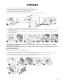
MACHINE PREPARATION
1. HANDLING THE PACKED MACHINE
Total weight is 40 lbs. per box.
Overall dimensions are:
A: 10.6 in (270 mm)
B: 19.2 in (487 mm)
C: 27.5 in (698 mm)
2. HOW TO UNPACK THE MACHINE
1. Place the lower part of the outer packaging in contact with the floor.
2. Open the outer box.
3. Remove the accessories from the box and carefully lay them on the ground.
4. Take the MotoMop out of the box.
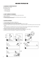
3. MACHINE ASSEMBLY
1. Take the package to the maintenance department.
2. Remove the MotoMop and all the accessories from the box.
3. Insert the lower tube (1) of the control handle into the hole on the joint (2) (Fig.1).
4. Attach the handle to the joint using the screw and nut (3), making sure the hole in the handle aligns with the hole on the joint
(Fig.2).
5. Lock the handle in the horizontal position. Rest your foot on the main part of the machine to prevent it from tilting, then
push the handle away from you until it snaps into the horizontal position (Fig.3).
6. Rotate the stop lever of the handle (4) in the direction of the arrow (Fig.4).
7. Collapse the handle by pushing the handle (5) towards the main body of the machine (Fig.5).
8. Rotate the lock lever of the handle (4) in the direction of the arrow (Fig.6).

7
4. HANDLING AND TRANSPORTATION OF THE UNPACKED
MACHINE
The procedure for the safe handling of the machine is the following:
1. If the machine is in operation, turn it off via the main switch (1)
(Fig.1).
2. Empty the recovery tank.
3. Empty the solution tank.
4. Remove the battery (2) from the machine. To remove the battery,
slide the stop lever (3) in the direction of the arrow (Fig.2).
5. Remove the battery from the machine using the handle molded into
it (Fig.3).
6. Lock the handle in the horizontal position. Rest your foot on the
main part of the machine to prevent it from tilting, then push the
handle away from you until it snaps into the horizontal position
(Fig.4).
7. Rotate the stop lever of the handle (4) in the direction of the arrow
(Fig.5).
8. Collapse the handle by pushing the handle (5) towards the main
part of the machine (Fig.6).
9. Rotate the lock lever of the handle (4) in the direction of the arrow
(Fig.7).
10. To raise the device off the floor, use the handle (6) at the back of the
machine (Fig.8).
MACHINE PREPARATION

8
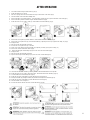
MACHINE PREPARATION
5. CHARGING THE BATTERY
The battery must be charged prior to the first use, and when it is discharged from use. To recharge the battery, proceed as
follows:
1. Take the machine to its battery recharging area.
2. If the machine is working, turn it off via the main switch (1) (Fig. 1).
3. Lock the handle in the vertical position.
4. Read the battery charger manual (supplied with the device) before inserting the power plug (2) in the power supply unit (3)
(Fig.2).
5. Plug the power plug (2) into an appropriate electrical outlet.
6. Remove the cap (5) covering the battery power socket (Fig.4).
7. Insert the battery charger power cable plug (6) in the socket (7) on the battery (Fig.5).
8. Perform a complete battery charging cycle.
9. Once the charging cycle is completed, remove the plug (2) on the battery charger from its electrical power outlet.
10. Take the power cable plug (6) out of the socket (7) on the battery.
11. Insert the cap (5) that covers the battery power socket.
6. CONNECTING THE BATTERY
Insert the battery (6) in the battery compartment (7) in the rear part of the machine (Fig.7).
Push the battery until the uncoupling lever (8) locks into place.

9
7. BATTERY MAINTENANCE AND DISPOSAL
To power the MotoMop, use only the battery supplied in the package or supplied by a Betco authorized service provider.
OTHER BATTERY TYPES CANNOT BE USED.
The MotoMop is powered by a lithium-ion battery. The battery compartment can accommodate a single battery slot at 25.55V.
MACHINE PREPARATION
8. PREPARING FOR WORK CYCLE
Before beginning to work, it is necessary to:
1. Before using the machine, make sure it is in a good, safe working condition. If there are items that are is not in order, the
machine must not be used.
2. Position the handle so it is vertical.
3. Activate the machine using the main switch (1) (Fig.1).
4. Check the battery charge level. There are four LEDs (2) on the battery to show the charge percentage (Fig.2). If all the LEDs
are lit up, the battery is fully charged; if they are all switched off, the battery is completely discharged.
5. Turnoff the machine using the main switch (1) (Fig.3).
6. Remove the battery (3) from the machine. To free the battery, slide the lock lever (4) in the direction of the arrow (Fig.4).
7. Remove the battery from the machine using the molded handle (Fig.5).
8. Make sure the condition of the squeegee blades are suitable for the work you want to perform. If they are damaged, perform
the necessary maintenance (read “MAINTENANCE”).
9. Make sure the condition of the brush is suitable for the work you want to perform. If it worn, perform the necessary
maintenance (read “MAINTENANCE”).
10. Rotate the front cover (5) as far as it will go - do this with the aid of handle (6) (Fig.6).
11. Remove the solution tank from the device (Fig.7). Carefully place it on the floor.
12. Remove the detergent solution filling cap (7) from its seat on the solution tank (Fig.8).
13. Fill with clean water, at a temperature no higher than 120° F and no lower than 50° F.
14. Add the liquid detergent to the solution tank in the concentration and manner indicated on the detergent manufacturer's
label.
15. Replace the detergent solution filling cap (7) in its seat on the solution tank (Fig.9).
16. Insert the solution tank in the device (Fig.10).
17. Rotate the front cover (5) as far as the work position - do this with the aid of the handle (6) (Fig.11).
18. Insert the battery in the battery compartment in the rear part of the device.

10
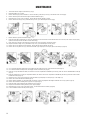
1. Carry out the operations described in the “PREPARING TO WORK” chapter.
2. Check that the squeegee body is in contact with the surface to be cleaned. If it isn't, turn the knob (1) in the direction of the
arrow (Fig.1).
3. Release the handle from its vertical position and rotate it towards you.
4. Adjust the length of the handle.
5. Activate the machine using the main switch (2) (Fig.2).
6. Activate the detergent solution supply by pressing the electric pump control switch (3) (Fig.3).
7. The machine will now begin to work until the battery is discharged or until the detergent solution runs out.
OPERATION

11
1. Turn off the machine using the main switch (1) (Fig.1).
2. Rotate the handle so it is vertical.
3. Raise the squeegee off the floor and rotate the knob (2) in the direction of the arrow (Fig.2).
4. Take the machine to the waste water drainage area.
5. Remove the battery (3) from the machine. To free the battery, slide the stop lever (4) in the direction of the arrow (Fig.3).
6. Remove the battery from the machine using the handle molded into it (Fig.4).
7. Rotate the front cover (5) as far as it will go - do this with the aid of the handle (6) (Fig.5).
8. Remove the recovery tank (7) from the machine - do this with the aid of the handle (8) (Fig.6).
9. Remove the recovery tank cover (9), then rotate the handle (8) completely to free the pin (10) from the clamp (11) (Fig.7).
10. Empty the tank.
11. Rinse the inside of the tank with clear water.
12. Position the recovery tank cover (9) on the tank.
13. Fix the cover on the tank, then rotate the handle (8) completely to locking pin (10) on the clamp (11).
14. Remove the solution tank from the device (Fig.8).
15. Remove the detergent solution filling cap (12) from its seat on the solution tank (Fig.9).
16. Empty the tank.
17. Rinse the inside of the tank with clear water.
18. Replace the detergent solution filling cap (12) in its seat on the solution tank (Fig.10)
19. Insert the two tanks in the machine, positioning first the solution tank and then the recovery tank.
20. Rotate the front cover (5) as far as the work position - do this with the aid of the handle (6) (Fig.11).
21. Lock the handle in the horizontal position (Fig.12).
22. Rotate the stop lever of the handle (13) in the direction of the arrow (Fig.13).
23. Collapse the handle by pushing the handle (14) towards the main part of the machine (Fig.14).
24. Rotate the stop lever of the handle (13) in the direction of the arrow (Fig.15).
25. Take the machine to its storage area.
26. Position the machine with its rear part in contact with the floor (Fig.16).
AFTER OPERATION

12
1. Turn off the machine using the main switch (1) (Fig.1).
2. Rotate the handle so it is vertical.
3. Remove the battery (2) from the machine. To remove the battery, slide the stop lever (3) in the direction of the arrow (Fig.2).
4. Remove the battery from the machine using the handle molded into (Fig.3).
5. Rotate the front cover (4) as far as it will go - do this with the aid of the handle (5) (Fig.4).
6. Remove the brush housing cover (6) and slide the stop levers (7) as indicated by the arrows (Fig.5).
7. Remove the brush (8) from the machine (Fig.6).
8. Clean the brush under running water to remove any impurities present in the bristles. Check that the bristles are not worn; in the event of excessive wear,
replace the brush (the bristles should be at least 10 mm long).
9. Fit the brush (8) on the pin in the brush motor (the brush can only be inserted in one direction) (Fig.7).
10. Replace the brush housing cover (6) and slide the stop levers (7) as indicated by the arrows (Fig.8)
11. Remove the recovery tank (9) from the machine - do this with the aid of the handle (10) (Fig.9).
12. Remove the recovery tank cover (11), then rotate the handle (10) completely to free the pin (12) from the clamp (13) (Fig.10).
13. Use a clear water and then a damp cloth to thoroughly clean the rotation pivot (14) of the vacuum motor floats (Fig.11).
14. Use clear water and then a damp cloth to thoroughly clean the central float (15) (Fig.12).
15. Clean the recovery tank with clear water; the entrance hole to this compartment is identified by the letter (A), while the outlet is identified with the letter (B)
(Fig. 13).
16. Clean the vacuum motor air conveyor compartment with air; the entrance hole to this compartment is identified by the letter (C), while the outlet is identi-
fied with the letter (D) (Fig. 14).
17. Replace the cover on the recovery tank, then rotate the handle (10) completely to lock the pin (12) on the clamp (13).
18. Remove the solution tank from the machine (Fig.15).
19. Remove the filter cartridge (17) and clean it with clear water to remove any impurities that might be attached. If necessary, replace it (Fig.16).
20. Remove the vacuum duct cleaning brush (18) from its support (Fig.17).
21. Clean the inside of the vacuum duct (19) with the brush (18) (Fig.18).
22. Replace the vacuum duct cleaning brush (18) in its support (Fig.19).
23. Rotate the front cover (4) as far as the work position - do this with the aid of the handle (5) (Fig.20).
24. Lock the handlebar in the horizontal position (Fig.21).
MAINTENANCE

13
25. Rotate the stop lever of the handle (20) in the direction of the arrow (Fig.22).
26. Collapse the handle, pushing the handle (21) towards the main part of the machine (Fig.23).
27. Rotate the clamp lever of the handle (20) in the direction of the arrow (Fig.24).
28. Position the machine with its rear part in contact with the floor (Fig.25).
29. Make sure the squeegee is in the work position. To do this rotate the knob (22) in the direction of the arrow (Fig.26).
31. Bring the squeegee coupling to the maintenance position and shift the knob (22) outwards (Fig.27). Rotate the squeegee coupling towards you (Fig.28).
30. Use a damp cloth to thoroughly clean the vacuum nozzle duct (23) (Fig.29).
31. Use a damp cloth to thoroughly clean the vacuum chamber of the squeegee (25) (Fig.30).
32. Use a damp cloth to thoroughly clean the front blade (26) of the squeegee (Fig.31). Check the condition of the front blade; if the edge that is in contact with
the floor is worn, replace it.
33. Use a damp cloth to thoroughly clean the rear blade (27) of the squeegee (Fig.32). Check the condition of the rear blade; if the edge that is in contact with
the floor is worn, replace it.
Careful maintenance of the squeegee blades guarantees better cleaning and drying of the floor, as well as a longer vacuum motor life. To replace the
squeegee blades, proceed as follows:
Turn the wing nuts (28) that hold the squeegee by 90° (Fig.33). Remove the squeegee from the slots on the squeegee connector, taking care not to lose
the seal on the vacuum nozzle (Fig.34).
Replace the worn/damaged blades.
Repeat the operations in reverse order to reassemble all the parts.
34. Bring the squeegee coupling to the idle position and shift the squeegee towards the machine (Fig.35).
35. Lock the squeegee coupling in the idle position. Push the knob (22) towards the machine (Fig.36), then rotate it in the direction of the arrow (Fig.38).
36. Remove the exhaust air filter support (29) from the machine by pressing the locking tab (30) in the direction of the arrow (Fig.38).
37. Clean the filter cartridges (31) with a jet of air (Fig.39), from a distance of at least 8 inches.
Careful maintenance of the exhaust air filters guarantees a longer vacuum motor life. To replace the filter cartridges, proceed as follows:
MAINTENANCE

14
Remove the filter cartridge supports (32) from the filter support (Fig.40).
Remove the worn filter cartridge (31) from the filter cartridge support (32) and replace it with the new one (Fig.41). Repeat the operations in reverse order
to reassemble all the parts.
38. Insert the exhaust air filter support (29) in the machine (Fig.42).
39. Rotate the machine to its work position (Fig.43).
40. Lock the handle in the vertical position; to release the handle, move the stop (33) in the direction of the arrow (Fig.44).
41. Rotate the front cover (4) as far as it will go - do this with the aid of the handle (5) (Fig.45).
42. Insert the two tanks and the detergent solution filter cartridge in the machine, positioning first the detergent solution filter cartridge, then the solution tank,
and finally the recovery tank.
43. Rotate the front cover (4) as far as the work position - do this with the aid of the handle (5) (Fig.46).
44. Insert the battery in the battery compartment in the rear part of the machine (Fig.47).
45. Position the machine with its rear part in contact with the floor (Fig.48).
MAINTENANCE

15
DISPOSAL
To dispose of the machine, take it to a re-cycling center or an authorized collection center. Before scrapping the machine,
it is necessary to remove and separate out the following materials, then send them to the appropriate collection centers in
accordance with applicable environmental regulations:
• Brush
• Electric and electronic parts*
• Battery
• Plastic parts
• Metallic parts
(*) In particular, contact your distributor when scrapping electric and electronic parts.

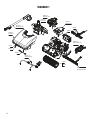
16
DIAGRAM 1
Diagram 6
Front Cover
Diagram 3
Handle Assembly
Diagram 5
Rear Cover
Diagram 8
Recovery Tank
Diagram 7
Solution Tank
Diagram 9
Vacuum Assembly
Diagram 4
Squeegee Assembly
E84717
E84718
Diagram 10
Solution Delivery
E84752
E84738
E84748
E84751
E22195
E84716

17
DIAGRAM 1 PARTS LISTING
E84738 LITHIUM ION BATTERY 1
E84717 CYLINDRICAL BRUSH, BLUE, PPL 0.3 1
E84718 CYLINDRICAL BRUSH, BLACK, PPL 0.2 1
E84748 MAINTENANCE BRUSH 1
E84752 BATTERY CHARGER 1
E22195 WASHER, FLAT M4 X 12 X 1 2
E84716
SCREW, PAN HEAD, PHIL SELF TAPPING M3.5 X 14 MM LG SS 8
E84751
SCREW, PAN HEAD, PHIL SELF TAPPING M4 X 8 MM LG SS
2
Part # Description Qty. Part # Description Qty.

18
DIAGRAM 2 MAIN BODY
8

19
DIAGRAM 2 PARTS LISTING
E84706 BRUSH COVER ASSEMBLY 1
E83702 WASHER, FENDER M6 X 24 MM X 2 MM 2
E84711 SCREW, SOCKET BUTTON HEAD M6 X 30 MM LG 1
E82314 NUT, HEX NYLOC M6 1
E84721 HUB COVER 1
E84743 BUSHING 1
E84746 BEARING 2
E84747 COVER LOCK 2
E84707 BRUSH MOTOR, 24V 32W 375RPM 1
E82446 SPRING 1
E83899 SCREW, PAN HEAD PHIL M5 X 10 MM LG 5
E84708 WASHER, FENDER, M3 X 12 X 0.8 1
E84709 WASHER, SERRATED LOCK 1
E84710 SCREW, FLAT HEAD PHIL M3 X 8 MM LG 2
E84712 BOLT, HEX M3 X 12 MM LG 1
E20249 NUT, HEX NYLOC M12 1
E84713 LED HEAD LIGHT 1
E84714 SMALL REAR WHEEL 2
E84715 CONTROLLER CARD 1
E84716
SCREW, PAN HEAD, PHIL SELF TAPPING M3.5 X 14 MM LG
4
E84719 BRUSH COVER REINFORCEMENT 1
E84720 LOWER BODY FRAME 1
E84722 CLAMP 1
E84723 ROUTING COVER 1
E84724 VACUUM MOTOR FILTER COVER 1
E84725 FILTER HOLDER 2
E84726 VACUUM MOTOR COVER 1
E84727 BATTERY RELEASE LEVER 1
E84728 BATTERY BOX LOWER COVER 1
E84729 BATTERY ELECTRICAL CONTACTS 1
E84730 COVER SUPPORT GUIDE 1
E84731 WATER PUMP COVER 1
E84732 SQUEEGEE POSITION KNOB LEFT 1
E84733 SQUEEGEE POSITION KNOB RIGHT 1
E84734 SQUEEGEE POSITION LEVER LEFT 1
E84735 SQUEEGEE POSITION LEVER RIGHT 1
E84736 WHEEL COVER 2
E84737 BRUSH DRIVER 1
E84739 MAIN WHEEL 2
E84740 WHEEL SPACER 2
E84741 WHEEL AXLE 2
E84742 BUSHING 1
E84744 COVER PIVOT PIN 2
E84745 COVER SUPPORT 1
E84749 VACUUM MOTOR FILTER 2
E84750
SCREW, PAN HEAD, PHIL SELF TAPPING M3 X 10 MM LG
15
E84753 MOTOR WASHER 1
E84754 O-RING 2
E84755 SUPPORT BRACKET 1
Part # Description Qty. Part # Description Qty.

20
DIAGRAM 3 HANDLE ASSEMBLY
E84750
E84762
E84761
E84767
E81649
E84763
E84764
E83837
E84758
E84757
E84759
E84765
E84760
E81654
E84766
Page is loading ...
Page is loading ...
Page is loading ...
Page is loading ...
Page is loading ...
Page is loading ...
Page is loading ...
Page is loading ...
Page is loading ...
Page is loading ...
Page is loading ...
Page is loading ...
Page is loading ...
Page is loading ...
Page is loading ...
Page is loading ...
-
 1
1
-
 2
2
-
 3
3
-
 4
4
-
 5
5
-
 6
6
-
 7
7
-
 8
8
-
 9
9
-
 10
10
-
 11
11
-
 12
12
-
 13
13
-
 14
14
-
 15
15
-
 16
16
-
 17
17
-
 18
18
-
 19
19
-
 20
20
-
 21
21
-
 22
22
-
 23
23
-
 24
24
-
 25
25
-
 26
26
-
 27
27
-
 28
28
-
 29
29
-
 30
30
-
 31
31
-
 32
32
-
 33
33
-
 34
34
-
 35
35
-
 36
36


Ask a question and I''ll find the answer in the document
Finding information in a document is now easier with AI
Related papers
-
BETCO E29942-00 Owner's manual
-
-
-
-
-
-
-
-
-
Other documents
-
 Triple S 20C Operating Instructions Manual
-
Powr-Flite PAS14G User manual
-
 Triple S Ace 20T User manual
-
Tennant T600e User manual
-
Alfa Network A500 User manual
-
Nobles SPEED SCRUB Service Information Manual
-
Minuteman E Ride ER32DQP User manual
-
COMAC C130 B User manual
-
-
Trident T20SC PRO Use and Maintenance Manual

