DNRECL Eclipse Duct Smoke Detector
INSTALLATION AND MAINTENANCE INSTRUCTIONS
3825 Ohio Avenue, St. Charles, Illinois 60174
1-800-SENSOR2, FAX: 630-377-6495
www.systemsensor.com
Table of Contents Page
[1] Limitations of Duct Smoke Detectors .........................1
[2] General Description .....................................1
[3] Contents of the Duct Smoke Detector Kit ......................1
[4] Detector Installation .....................................1
[5] Sampling Tube Installation ................................2
[6] Measurement Tests ......................................3
[7] Field Wiring ...........................................4
[8] Verification of Operation ..................................4
[9] Dectector Cleaning Procedures .............................5
[10] Sensor Replacement ....................................5
[11] Optional Accessories ....................................5
Warranty .............................................6
BEFORE INSTALLING
Read System Sensor’s Applications Guide for Duct Smoke Detectors (HVAG53),
which provides detailed information on detector spacing, placement, zon-
ing, wiring, and special applications. This manual is avilable online at
www.systemsensor.com. NFPA Standards 72 and 90A should also be refer-
enced for detailed information.
NOTICE: This manual shall be left with the owner/user of this equipment.
IMPORTANT: This detector must be tested and maintained regularly following
NFPA 72 requirements. The detector must be tested an maintained regularly
following NFPA 72 requirements. According to NFPA, the detector should be
visually inspected semiannually and functionally tested at least once a year.
This may need to be more frequent depending on the air quality of the duct
supply air.
[1] LIMITATIONS OF DUCT SMOKE DETECTORS
WARNING
The National Fire Protection Association has established that DUCT DETEC-
TORS MUST NOT BE USED AS A SUBSTITUTE FOR OPEN AREA DETECTOR
PROTECTION as a means of providing life safety. Nor are they a substitute for
early warning in a building’s regular fire detection system.
System Sensor supports this position and strongly recommends that the user
read NFPA Standards 90A, 72, and 101. The DNRECL Air Duct Smoke Detec-
tors are listed per UL 268A.
This device will not operate without electrical power. Fire situations may
cause an interruption of power. The system safeguards should be discussed
with your local fire protection specialist.
This device will not sense smoke unless the ventilation system is operating
and the cover is installed.
For this detector to function properly, it MUST be installed according to the
instructions in this manual. Furthermore, the detector MUST be operated within
ALL electrical and environmental specifications listed in this manual and the
sensor head installation manual. Failure to comply with these requirements
may prevent the detector from activating when smoke is present in the air duct.
[2] GENERAL DESCRIPTION
Smoke introduced into this air duct system will be distributed throughout the
entire building. Smoke detectors designed for use in air duct systems are used
to sense the presence of smoke in the duct.
Model DNRECL Air Duct Smoke Detector utilizes photoelectric technology for
the detection of smoke. This detection method, when combined with an ef-
ficient housing design, samples air passing through the duct and allows detec-
tion of a developing hazardous condition. When sufficient smoke is sensed,
an alarm signal is initiated at the fire control panel monitoring the detector,
and appropriate action can be taken to shut off fans, blowers, change over air
handling systems, etc. These actions can facilitate the management of toxic
smoke and fire gases throughout the areas served by the duct system.
The DNRECL incorporates a sensor cover tamper feature that provides a trou-
ble signal at the panel immediately if the cover is removed or improperly in-
stalled. Proper installation of the sensor cover removes the trouble condition.
If programmed with the system control panel, two LEDs on each duct smoke
detector light to provide local visible indication.
The DNRECL provides a remote alarm output and remote test capability with
the RTS451/RTS151 or RTS451KEY/RTS151KEY Remote Test Stations.
[2.1] DETECTOR FEATURE SET
– Utilizes plug-in head
– Sampling tubes install from front and rear
– Compatible with existing accessories
– Able to address detector per code switches on sensor head.
[3] CONTENTS OF THE DUCT SMOKE DETECTOR KIT
1. Sensor/power board assembly and covers (use appropriate sensor per
the system control panel)
2. Three #10 sheet metal screws for mounting
3. Drilling template
4. One sampling tube end cap
5. One plastic exhaust tube
NOTE: A sampling tube must be ordered to complete the installation. It must
be the correct length for the width of the duct where it will be installed. See
Table 1 on page 3 to determine the inlet tube required for different duct widths.
[4] DETECTOR INSTALLATION
[4.1] VERIFY DUCT AIR FLOW DIRECTION AND VELOCITY
Model DNRECL detectors are designed to be used in air handling systems hav-
ing air velocities of 300 to 4000 feet per minute. Duct widths from 6 inches to
12 feet can be accommodated. Be sure to check engineering specifications to
ensure that the air velocity in the duct falls within these parameters. If neces-
sary, use a velocity meter (anemometer) to check the air velocity in the duct.
I56-3496-006R
SPECIFICATIONS
Operating Temperature: –4° to 158° F (–20° to 70° C)
Storage Temperature: –4° to 158° F (–20° to 70° C)
Humidity: 0% to 95% Relative Humidity Non-condensing
Air Velocity: 300 to 4000 ft./min. (1.5 to 20.3 m/sec.)
Rectangular Footprint Dimensions: 14.38 in L x 5 in W x 2.5 in D (37 cm L x 12.7 cm W x 6.36 cm D)
Square Footprint Dimensions: 7.75 in L x 9 in W x 2.5 in D (19.7 cm L x 22.9 cm W x 6.35 cm D)
Weight: 1.6 pounds; 0.73 kg
Electrical (See applicable detector head installation manual for electrical specifications. Use the Base/Sensor Cross Reference chart at http:\\www.systemsensor.com
to determine applicable sensor head.)
ACCESSORY CURRENT LOADS AT 24 VDC
DEVICE STANDBY ALARM
RTS451/RTS151 0mA 12mA Max.
RTS451KEY/RTS151KEY 12mA 12mA Max.
1 I56-3496-006R
07-07

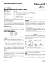
SENSOR HEAD
SENSOR MODULE COVER
WIRING COMPARTMENT COVER
WIRING COMPARTMENT
SENSOR MODULE
EXHAUST TUBE
SAMPLING
TUBE
SOLD
SEPERATELY
[4.2] DETERMINE MOUNTING LOCATION AND CONFIGURATION
On ducts wider than 18 inches it is recommended that the detector be
mounted downstream of a bend, obstruction in the duct, or the supply or
return air inlet.
Exception: Installation of duct detectors can be on or within a commercial
packaged rooftop heating and air-conditioning system, fire/smoke dampers
and economizers. They may be mounted in either the supply and/or return
air section as determined by local code.
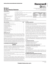
Once a suitable location is selected, determine if the detector is to be mounted
in a side-by-side “rectangular” configuration or a top-over-bottom “square”
configuration as shown in Figure 2. If mounting in the square configuration,
remove the rear attachment screw, rotate the unit at hinge, and replace the
screw into the new attachment hole as shown in Figure 2. Do NOT remove
the hinge screw during this process. Final installation approval shall be
based upon passing differential pressure and smoke entry tests described in
the Measurement Tests section.
FIGURE 2:
REMOVE SCREW AND PIVOT
DETECTOR AS SHOWN BELOW.
REPLACE SCREW
TO SECURE DETECTOR
IN PLACE.
H0550-00
[4.3] DRILL THE MOUNTING HOLES
Remove the paper backing from the mounting template supplied. Affix the
template to the duct at the desired mounting location. Make sure the template
lies flat and smooth on the duct.
[4.3.1] FOR RECTANGULAR SIDE-BY-SIDE MOUNTING CONFIGURATION:
Center punch at (4) target centers: (2) “A” for sampling tubes and (2) “B” for
the rectangular configuration mounting tabs as shown on mounting template.
Drill pilot holes at target “A” centers and cut two 1.375 inch diameter holes
using a
13
⁄8 inch hole saw or punch. Drill .156 inch diameter holes using a
5
⁄32
inch drill at target “B” centers.
[4.3.2] FOR SQUARE TOP-OVER-BOTTOM MOUNTING CONFIGURATION:
Center punch at (4) target centers: (2) “A” for sampling tubes and (2) “C” for
the square configuration mounting tabs as shown on mounting template. Drill
pilot holes at target “A” centers and cut two 1.375 inch diameter holes using
a 1
3
⁄8 inch hole saw or punch. Drill .156 inch diameter holes using a
5
⁄32 inch
drill at target “C” centers. If desired, drill an additional .156 inch hole at the
location of one of the mounting tabs on the lower housing.
[4.4] SECURE THE DUCT DETECTOR TO THE DUCT
Use two (rectangular configuration) or three (square configuration) of the pro-
vided sheet metal screws to screw the duct detector to the duct.
CAUTION: Do not overtighten the screws.
[5] SAMPLING TUBE INSTALLATION
[5.1] SAMPLING TUBE SELECTION
The sampling tube must be purchased separately. Order the correct length,
as specified in Table 1, for width of the duct where it will be installed. The
sampling tube length must extend at least
2
/3 across the duct width for optimal
performance.
The sampling tube is always installed with the air inlet holes facing into the
air flow. To assist proper installation, the tube’s connector is marked with an
arrow. Make sure the sampling tube is mounted so that the arrow points into
the airflow as shown in Figure 3. Mounting the detector housing in a vertical
orientation is acceptable provided that the air flows directly into the sam-
pling tube holes as indicated in Figure 3. The sampling tube and exhaust tube
can be mounted in either housing connection as long as the exhaust tube is
mounted downstream from the sampling tube.
FIGURE 1. EXPLODED VIEW OF DUCT SMOKE DETECTOR COMPONENTS:
H0569-07
2 I56-3496-006R
07-07

FIGURE 4.
DETECTOR
3
/
4
˝
HOLE
12˝
1
/
4
˝
2˝
H0215-00
[5.3] MODIFICATIONS OF SAMPLING TUBES
There may be applications where duct widths are not what is specified for the
installation. In such cases, it is permissible to modify a sampling tube that is
longer than necessary to span the duct width.
Use a 0.193-inch diameter (#10) drill and add the appropriate number of holes
so that the total number of holes exposed to the air flow in the duct is 10 to 12.
Space the additional holes as evenly as possible over the length of the tube.
CAUTION: This procedure should only be used as a temporary fix. It is not
intended as a permanent substitute for ordering the correct length tubes.
[5.4] REMOTE SAMPLING TUBE INSTALLATION
The detector arrangement can also incorporate the remote mounting of the
sampling tube and/or exhaust tube. In this case both the detector, sampling
tube and exhaust tube (if included) should be rigidly mounted to withstand
the pressure and vibrations caused by the air velocity. The location of the
detector’s sampling tube should be such that there is uniform airflow in the
cross section area.
Pressure differential across the sampling and exhaust ports in the detector hous-
ing shall be verified to be between 0.01 and 1.11 inches of water. Do so by mea-
suring the pressure difference between the inlet and outlet ports on the detector
housing using a manometer as described in the Measurement Tests sectiont of
this manual.
[6] MEASUREMENT TESTS
[6.1] AIR FLOW
The DNRECL is designed to operate over an extended air speed range of 300
to 4000 FPM. To verify sufficient sampling of ducted air, turn the air handler
on and use a manometer to measure the differential pressure between the two
sampling tubes. The differential pressure should measure at least 0.01 inches
of water and no more than 1.11 inches of water. Because most commercially
available manometers cannot accurately measure very low pressure differen-
tials, applications with less than 500 FPM of duct air speed may require one
of the following: 1) the use of a current-sourcing pressure transmitter (Dwyer
Series 607) or 2) the use of aerosol smoke, see below for test descriptions.
TABLE 1. SAMPLING TUBES RECOMMENDED FOR
DIFFERENT DUCT WIDTHS:
Outside Duct Width Sampling Tube Recommended*
Up to 1 ft. DST1
1 to 2 ft. DST1.5
2 to 4 ft. DST3
4 to 8 ft. DST5
8 to 12 ft. DST10 (2-piece)
*Must extend a minimum of
2
⁄3 the duct width
FIGURE 3. AIR DUCT DETECTOR SAMPLING TUBE:
SAMPLING TUBE ENDCAP
ARROW MUST FACE
INTO AIR FLOW
AIR FLOW
DIRECTION
CAUTION: The sampling tube end cap, included with the detector, is critical
to proper operation of the duct smoke detector. The end cap is needed to
create the proper air flow to the sensor of the duct smoke detector. Once any
sampling tube length adjustments are made, plug the end of the sampling
tube with the provided end cap.
A plastic exhaust tube is included with the unit to be installed if needed. In-
stall into the housing connection that is downstream from the sampling tube
connection. The exhaust tube can be installed from the front of the detector
or the back. A longer 1 foot exhaust tube, model ETX, is available as an acces-
sory in cases where the molded exhaust tube does not extend at least 2 inches
into the duct.
[5.2] SAMPLING TUBE INSTALLATION
1. For tubes shorter than the width of the duct, slide the sampling tube,
with installed end cap, into the housing connection that meets the air-
flow first. Position the tube so that the arrow points into the airflow as
shown in Figure 3. Per NFPA sampling tubes over 3 feet long should be
supported at the end opposite of the duct detector. In ducts wider than 8
feet, work must be performed inside the duct to couple the other section
of the sampling tube to the section already installed using the ½ inch
conduit fitting supplied. Make sure that the holes on both sections of the
air inlet sampling tube are lined up and facing into the airflow.
2. For tubes longer than the width of the air duct, the tube should extend
out of the opposite side of the duct. Drill a ¾ inch hole in the duct op-
posite the hole already cut for the sampling tube. Ensure that the sam-
pling tube is angled downward from the duct smoke detector to allow for
moisture drainage away from the detector. The sampling tube should
be angled at least
1
⁄4” downward for every 12” of duct width per Figure
4.There should be 10 to 12 holes spaced as evenly as possible across the
width of the duct. If there are more than 2 holes in the section of the tube
extending out of the duct, select a shorter tube using Table 1. Otherwise,
trim the tube to leave approximately 1 to 2 inches extending outside the
duct. Plug the end with the end cap and tape closed any holes in the
protruding section of the tube. Be sure to seal the duct where the tube
protrudes.
NOTE: Air currents inside the duct may cause excessive vibration, especially
when the longer sampling tubes are used. In these cases, a 3 inch floor flange
(available at most plumbing supply stores) may be used to fasten the sam-
pling tube to the other side of the duct. When using the flange/connector
mounting technique, drill a 1 to 1 ¼ inch hole where the flange will be used
HIGH
LOW
9 VOLT
BATTERY
9 VOLT
BATTERY
9 VOLT
BATTERY
TO SAMPLING TUBE
TO EXHAUST TUBE
DIFFERENTIAL
PRESSURE
TRANSMITTER
MODEL #607-01
15 TO 36
VDC SUPPLY
1000 OHM 5%
1 WATT RESISTOR
VOLT METER FLUKE
MODEL 87 OR
EQUIVALENT
+–
H0163-01
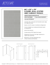
FIGURE 5. PROCEDURE FOR VERIFYING AIR FLOW:
H0551-00
3 I56-3496-006R
07-07

-
+
LISTED COMPATIBLE
CONTROL PANEL
OPTIONAL RETURN LOOP
(–) COM LINE
TO REST OF SYSTEM
(+) COM LINE
TO REST OF SYSTEM
SLC
SLC
UNIT 2UNIT1
UNIT 3
COMM (+)
COMM (–)
(+) OUT
COMM (+)
COMM (–)
(+) OUT
COMM (+)
COMM (–)
(+) OUT
[6.2] LOW FLOW AIR FLOW TEST USING DWYER SERIES 607
DIFFERENTIAL PRESSURE TRANSMITTER
Verify the air speed of the duct using an anemometer. Air speed must be at
least 300 FPM. Wire the Dwyer transmitter as shown in Figure 5. Connect the
leads of the meter to either side of the 1000Ω resistor. Allow unit to warm up
for 15 seconds. With both HIGH and LOW pressure ports open to ambient air,
measure and record the voltage drop across the 1000Ω resistor (measurement
1), 4.00 volts is typical. Using flexible tubing and rubber stoppers, connect the
HIGH side of the transmitter to the sampling tube of the duct smoke detec-
tor housing, and the LOW side of the transmitter to the exhaust tube of the
duct smoke detector housing. Measure and record the voltage drop across the
1000Ω resistor (measurement 2). Subtract the voltage recorded in measure-
ment 1 from the voltage recorded in measurement 2. If the difference is greater
than 0.15 volts, there is enough air flow through the duct smoke detector for
proper operation.
[7] FIELD WIRING; INSTALLATION GUIDELINES
All wiring must be installed in compliance with the National Electrical Code
and the local codes having jurisdiction. Proper wire gauges should be used.
The conductors used to connect smoke detectors to control panels and acces-
sory devices should be color-coded to prevent wiring mistakes. Improper con-
nections can prevent a system from responding properly in the event of a fire.
For signal wiring (the wiring between detectors or from detector to auxiliary
devices), it is usually recommended that single conductor wire be no smaller
than 18 gauge. The duct smoke detector terminals accommodate wire sizes
up to 12 gauge. Flexible conduit is recommended for the last foot of conduit;
solid conduit connections may be used if desired.
Duct smoke detectors and alarm system control panels have specifications for
Signaling Line Circuit (SLC) wiring. Consult the control panel manufacturer’s
specifications for wiring requirements before wiring the detector loop.
[7.1] WIRING INSTRUCTIONS
Disconnect power from the communication line before installing the DNRECL
duct smoke detector.
The DNRECL detectors are designed for easy wiring. The housing provides a
terminal strip with clamping plates. Wiring connections are made by sliding
the bare end under the plate, and tightening the clamping plate screw. See
Figure 6 on below for system wiring.
1. Wire the detector housing per the wiring diagram, see Figure 5.
2. Install the detector head into the base. Push the detector into the base
while turning it clockwise to secure it in place.
3. Set the desired address using the IR configuration tool (EA–CT).
4. Test the duct detector as described in the Testing section of this manual.
NOTE: When using the EA–CT tool, the address/loop on a duct detector in
sight can be set or changed. However, if the duct detector is being commu-
nicated to as a target (out of sight device) through another device (in sight),
only the address of the target can be changed. Device in sight must be within
30ft. of the EA–CT in order for it to communicate.
CAUTION
Dust covers provide limited protection against airborne dust particles during
shipping. Dust covers must be removed before the detectors can sense smoke.
Remove detectors prior to heavy remodeling or construction.
[8] VERIFICATION OF OPERATION
[8.1] INSTALL THE COVER
Install the covers making sure that the cover fits into the base groove. Tighten
the seven screws that are captured in the covers. Note that the cover must be
properly installed for proper operation of the sensor.
[8.2] POWER THE UNIT
Activate the communication line on terminals COM + and COM —.
[8.3] DETECTOR CHECK
Standby - If programmed by the system control panel, look for the presence of
the flashing LEDs through the transparent housing cover. The LED will flash
with each communication.
Trouble - If programmed by the system control panel and the detector LEDs do
not flash, then the detector lacks power (check wiring, missing or improperly
placed cover, panel programming, or power supply), the sensor head is miss-
ing (replace), or the unit is defective (return for repair).
[8.4] DUCT SMOKE DETECTOR TEST & MAINTENANCE PROCEDURES
Test and maintain duct smoke detectors as recommended in NFPA 72. The
tests contained in this manual were devised to assist maintenance personnel
in verification of proper detector operation.
Before conducting these tests, notify the proper authorities that the smoke
detection system will be temporarily out of service. Disable the zone or system
under test to prevent unwanted alarms.
[8.4.1] TEST THE UNIT
Before replacing the duct housing cover, check the detector interconnections,
as follows:
A. Functional:
The duct detector head can be functionally tested by using the IR con-
figuration tool (EA-CT). Following the instructions, initiate the detector
test sequence. The detector should initiate a walk test message at the fire
alarm control panel. Refer to the control panel technical documentation
for further information.
B. RTS451/RTS451KEY Remote Test Station:
The RTS451/RTS451KEY Remote Test Station facilitates testing of the
duct detector alarm capability. This duct detector cannot be reset by the
RTS451/RTS451KEY. It must be reset at the system control panel.
[8.4.2] THE DETECTOR MUST BE RESET BY THE SYSTEM CONTROL PANEL
[8.4.3] SMOKE ENTRY TEST USING AEROSOL SMOKE
This test is intended for low-flow systems (300-500 FPM). If the air speed is
greater than 500 FPM, use a conventional manometer to measure differential
pressure between the sampling tubes, as described under Measurement Tests
on Page 3.
Drill a
1
⁄4 inch hole 3 feet upstream from the duct smoke detector. With the air
handler on, measure the air velocity with an anemometer. Air speed must be
at least 300 FPM. Spray aerosol smoke* into the duct through the
1
⁄4 inch hole
for five seconds. Wait two minutes for the duct smoke detector to alarm. If the
duct smoke detector alarms, air is flowing through the detector. Remove the
duct smoke detector cover and blow out the residual aerosol smoke from the
chamber and reset the duct smoke detector at the panel. Use duct tape to seal
the aerosol smoke entry hole. Remember to replace the cover after the test or
the detector will not function properly.
*Aerosol smoke can be purchased from Home Safeguard Industries at home-
FIGURE 6. SYSTEM WIRING DIAGRAM FOR DNRECL:
HO119-02
4 I56-3496-006R
07-07

safeguard.com, model 25S Smoke Detector Tester, and Chekkit Smoke De-
tector Tester model CHEK02 and CHEK06 available from SDi. When used
properly, the canned smoke agent will cause the smoke detector to go into
alarm. Refer to the manufacturer’s published instructions for proper use of the
canned smoke agent.
CAUTION
Canned aerosol simulated smoke (canned smoke agent) formulas will vary by
manufacturer. Misuse or overuse to these products may have long term ad-
verse effects on the smoke detector. Consult the canned smoke agent manufac-
turer’s published instructions for any further warnings or caution statements.
[9] DETECTOR CLEANING PROCEDURES
Notify the proper authorities that the smoke detector system is undergoing
maintenance, and that the system will temporarily be out of service. Disable
the zone or system undergoing maintenance to prevent unwanted alarms and
possible dispatch of the fire department.
[9.1] DETECTOR SENSOR
1. Remove the sensor to be cleaned from the system.
2. Remove the sensor cover by pressing firmly on each of the four removal
tabs that hold the cover in place.
3. Vacuum the screen carefully without removing it. If further cleaning is
required continue with Step 4, otherwise skip to Step 7.
4. Remove the chamber cover/screen assembly by pulling it straight out.
5. Use a vacuum cleaner or compressed air to remove dust and debris from
the sensing chamber.
6. Reinstall the chamber cover/screen assembly by sliding the edge over the
sensing chamber. Turn until it is firmly in place.
7. Replace the cover using the LEDs to align the cover and then gently
pushing it until it locks into place.
8. Reinstall the detector.
[9.2] REINSTALLATION
1. Reinstall the detector in its housing.
2. Restore system power.
3. Perform Detector Check.
4. Notify the proper authorities testing has been completed and the smoke
detector system is back in operation.
[10] SENSOR REPLACEMENT
1. Remove the sensor head by rotating counterclockwise.
2. Pull gently to remove it.
3. To replace the sensor head, align the mounting features and rotate clock-
wise into place.
[11] OPTIONAL ACCESSORIES
Optional accessories include RTS451/RTS151 and RTS451KEY/RTS151KEY.
RTS451/RTS451KEY
FIELD WIRED
WIRE CONNECTIO
N
REMOTE TEST STATION
LED OPTION
1 PER UNIT
8mA CURRENT DRAW
45
321
TEST COIL +
TEST COIL –
COMM +
OUT
(CONV ONLY) +
COMM –
RA/RTS –
RA +
RTS +
FIGURE 9: WIRING DIAGRAM FROM DNRECL TO RTS451/RTS151/RTS-
451KEY/RTS151KEY
HO571-11
5 I56-3496-006R
07-07

THREE-YEAR LIMITED WARRANTY
System Sensor warrants its enclosed product to be free from defects in materials and
workmanship under normal use and service for a period of three years from date of
manufacture. System Sensor makes no other express warranty for the enclosed product.
No agent, representative, dealer, or employee of the Company has the authority to in-
crease or alter the obligations or limitations of this Warranty. The Company’s obligation
of this Warranty shall be limited to the replacement of any part of the product which is
found to be defective in materials or workmanship under normal use and service during
the three year period commencing with the date of manufacture. After phoning System
Sensor’s toll free number 800-SENSOR2 (736-7672) for a Return Authorization number,
send defective units postage prepaid to: Honeywell, 12220 Rojas Drive, Suite 700, El Paso
TX 79936, USA. Please include a note describing the malfunction and suspected cause
of failure. The Company shall not be obligated to replace units which are found to be
defective because of damage, unreasonable use, modifications, or alterations occurring
after the date of manufacture. In no case shall the Company be liable for any consequen-
tial or incidental damages for breach of this or any other Warranty, expressed or implied
whatsoever, even if the loss or damage is caused by the Company’s negligence or fault.
Some states do not allow the exclusion or limitation of incidental or consequential dam-
ages, so the above limitation or exclusion may not apply to you. This Warranty gives you
specific legal rights, and you may also have other rights which vary from state to state.
Please refer to insert for the Limitations of Fire Alarm Systems
6 I56-3496-006R
©2016 System Sensor. 07-07
/