Page is loading ...

www.rosemount.com
Reference Manual
00809-0100-1191, Rev CB
May 2006
Rosemount 485 Annubar
®
Flow Handbook


Reference Manual
00809-0100-1191, Rev CB
May 2006
Rosemount 485 Annubar
www.rosemount.com
Table of Contents
SECTION 1
Fluid Flow Theory
Introduction . . . . . . . . . . . . . . . . . . . . . . . . . . . . . . . . . . . . . . . . . . . . . 1-1
Physical Fluid Properties . . . . . . . . . . . . . . . . . . . . . . . . . . . . . . . . . . . 1-1
Pressure . . . . . . . . . . . . . . . . . . . . . . . . . . . . . . . . . . . . . . . . . . . . . 1-1
Temperature . . . . . . . . . . . . . . . . . . . . . . . . . . . . . . . . . . . . . . . . . . 1-4
Density, Specific Weight, Specific Gravity . . . . . . . . . . . . . . . . . . . 1-4
Viscosity . . . . . . . . . . . . . . . . . . . . . . . . . . . . . . . . . . . . . . . . . . . . . 1-5
Nature of Fluid Flow in Pipes. . . . . . . . . . . . . . . . . . . . . . . . . . . . . . . . 1-6
Flow Patterns . . . . . . . . . . . . . . . . . . . . . . . . . . . . . . . . . . . . . . . . . 1-6
Average Velocity. . . . . . . . . . . . . . . . . . . . . . . . . . . . . . . . . . . . . . . 1-7
Reynolds Number. . . . . . . . . . . . . . . . . . . . . . . . . . . . . . . . . . . . . . 1-8
Bernoulli's Theorem . . . . . . . . . . . . . . . . . . . . . . . . . . . . . . . . . . . . 1-9
Actual and Standard Volumetric Flowrate for Gases . . . . . . 1-12
Actual and Standard Volumetric Flowrate for Liquids . . . . . . . . 1-15
SECTION 2
Annubar Primary
Element Flow
Calculations
Annubar Primary Element Flow Equations . . . . . . . . . . . . . . . . . . . . . 2-1
Nomenclature . . . . . . . . . . . . . . . . . . . . . . . . . . . . . . . . . . . . . . . . . . 2-7
Flow Coefficient Reynolds Number Dependency . . . . . . . . . . . . . 2-9
Flow Coefficient Theory . . . . . . . . . . . . . . . . . . . . . . . . . . . . . . . . . 2-9
Signal . . . . . . . . . . . . . . . . . . . . . . . . . . . . . . . . . . . . . . . . . . . . . . . 2-9
Shape Differential . . . . . . . . . . . . . . . . . . . . . . . . . . . . . . . . . . . . . 2-9
Blockage Differential. . . . . . . . . . . . . . . . . . . . . . . . . . . . . . . . . . . 2-10
The Importance of the Flow Coefficient, or K vs. B Theory . . . . . 2-10
Operating Limitations . . . . . . . . . . . . . . . . . . . . . . . . . . . . . . . . . . 2-11
Flow Calculation Examples: . . . . . . . . . . . . . . . . . . . . . . . . . . . . . 2-12
SECTION 3
Installation and
Operational
Errors . . . . . . . . . . . . . . . . . . . . . . . . . . . . . . . . . . . . . . . . . . . . . . . . . . 3-1
Alignment . . . . . . . . . . . . . . . . . . . . . . . . . . . . . . . . . . . . . . . . . . . . 3-1
Sizing . . . . . . . . . . . . . . . . . . . . . . . . . . . . . . . . . . . . . . . . . . . . . . . 3-2
Upstream Flow Disturbance . . . . . . . . . . . . . . . . . . . . . . . . . . . . . . . . 3-2
Instrument Lines and Connections Leakage . . . . . . . . . . . . . . . . . . . 3-4
Flow Parameter Changes . . . . . . . . . . . . . . . . . . . . . . . . . . . . . . . . . . 3-4
Dirt Accumulation. . . . . . . . . . . . . . . . . . . . . . . . . . . . . . . . . . . . . . . . . 3-4
Gas Entrapment. . . . . . . . . . . . . . . . . . . . . . . . . . . . . . . . . . . . . . . . . . 3-6
Flow Parameter Limitations . . . . . . . . . . . . . . . . . . . . . . . . . . . . . . . . . 3-6

Reference Manual
00809-0100-1191, Rev CB
May 2006
Rosemount 485 Annubar
TOC-2
APPENDIX A
Fluid Properties and Pipe
Data
Fluid Properties . . . . . . . . . . . . . . . . . . . . . . . . . . . . . . . . . . . . . . . . . . A-1
APPENDIX B
Pipe Data
APPENDIX C
Unit and Conversion
Factors
APPENDIX D
Related Calculations
Ideal and Real Specific Gravity . . . . . . . . . . . . . . . . . . . . . . . . . . . . . .D-1
Derivation of Annubar primary element flow equations . . . . . . . . . . . .D-3
APPENDIX E
Flow Turndown and
Differential Pressure
Requirements
Flow Turndown . . . . . . . . . . . . . . . . . . . . . . . . . . . . . . . . . . . . . . . . . . E-1
Differential Pressure (DP Turndown). . . . . . . . . . . . . . . . . . . . . . . . . . E-2
Accuracy and Flow Turndown . . . . . . . . . . . . . . . . . . . . . . . . . . . . . . . E-2
Flow Measurement System Turndown . . . . . . . . . . . . . . . . . . . . . . . . E-2
Percent of Value and Percent of Full Scale accuracy . . . . . . . . . . . . . E-2
Annubar Turndown Limitations . . . . . . . . . . . . . . . . . . . . . . . . . . . . . . E-3
Minimum measurable differential pressure . . . . . . . . . . . . . . . . . . . . . E-4
Putting it all together: The flow system turndown . . . . . . . . . . . . . . . . E-4
APPENDIX F
References
APPENDIX G
Variable List

Reference Manual
00809-0100-1191, Rev CB
May 2006
Rosemount 485 Annubar
www.rosemount.com
Section 1 Fluid Flow Theory
Introduction . . . . . . . . . . . . . . . . . . . . . . . . . . . . . . . . . . . . . . . . .page 1-1
Physical Fluid Properties . . . . . . . . . . . . . . . . . . . . . . . . . . . . . .page 1-1
Nature of Fluid Flow in Pipes . . . . . . . . . . . . . . . . . . . . . . . . . .page 1-6
INTRODUCTION The Emerson Process Management DP-Flow Engineering Department has
prepared this book to provide all of the information necessary to accurately
measure fluid flow using the Rosemount 485 Annubar primary element.
Fluid flow measurement involves many variables. In this handbook fluid
properties that affect flow measurement are discussed and defined. We hope
this will bring all readers to a point where they are comfortable with the flow
equations which follow. The flow equations are developed from Bernoulli's
Theorem, which is the application of the law of conservation of energy to fluid
flow. These equations are then developed and modified for use with 485
Annubar Flow Sensors. After all the terms have been defined and the
equations developed, you are then ready to do the precise flow calculations
necessary to apply an Annubar and an associated secondary readout
instrument to your flow situation.
We realize that many intricacies of fluid flow have been neglected in this book.
We feel that we have presented enough theory and data for you to accurately
measure fluid flow using the Annubar Flow Sensor. For difficult flow
measurement problems, contact your local Emerson Process Management
representative for assistance.
PHYSICAL FLUID
PROPERTIES
To solve any flow problem a knowledge of the physical properties of the fluid
is required. Appendix A gives fluid property data for the most common fluids.
Definitions and descriptions of the most common properties are given below.
Pressure Pressure is the force exerted by a fluid per unit area. The most common unit
of pressure measurement is pounds force per square inch (lbf/in
2
or psi) in the
English system of units and pascal or kilopascal (Pa or kPa) in the SI system
of units.
In most flow problems (especially gas flow problems), the absolute pressure
must be used in the calculations. However, most pressure gages measure a
pressure that is referenced to atmospheric pressure (atmospheric pressure =
0 psig or 0 kPa g). To obtain absolute pressure, the atmospheric pressure
must be added to the gage pressure. Vacuum gages measure a pressure that
is lower than atmospheric pressure. To obtain absolute pressure, the vacuum
pressure must be subtracted from the atmospheric pressure. All of these
pressure terms are described in detail below and the relationship between
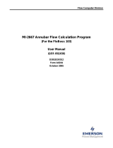
these pressures is shown graphically in Figure 1-1.

Reference Manual
00809-0100-1191, Rev CB
May 2006
Rosemount 485 Annubar
1-2
Figure 1-1. Pressure
Relationships
Absolute zero pressure, or a perfect vacuum, would exist if all molecules were
removed from an enclosed space. In reality, this is impossible to achieve, but
it does serve as a convenient reference for pressure measurement.
Atmospheric pressure is the amount of pressure exerted by the atmosphere
above absolute zero pressure. The “standard” atmospheric pressure used in
this handbook is 14.696 psia (101.325 kPa). It is important to realize that
atmospheric pressure at any one location varies with day to day weather
conditions. More important, the atmospheric pressure changes rapidly with
elevation above sea level. The following table gives the U.S. Standard
Atmosphere (1962) for various altitudes above sea level.
Table 1-1. Atmospheric
Pressure by Altitude
Absolute pressure that
is greater than
atmospheric pressure
Barometer reads
atmospheric pressure
Pressure above
atmospheric pressure
Atmospheric pressure
Pressure less than
atmospheric pressure
Perfect vacuum
Ordinary pressure gauge measures
pressure above atmospheric pressure
Ordinary vacuum gauge measures
pressure below atmospheric pressure
Absolute pressure that is less
than atmospheric pressure
Altitude Atmospheric Pressure
feet meters psia bar
0 0 14.696 1.01
500 152.4 14.433 0.995
1000 304.8 14.173 0.977
1500 457.2 13.917 0.959
2000 609.6 13.664 0.942
2500 762.0 13.416 0.925
3000 914.4 13.171 0.908
3500 1066.8 12.930 0.891
4000 1219.2 12.692 0.875
4500 1371.6 12.458 0.859
5000 1524.0 12.227 0.843
6000 1828.8 11.777 0.812
7000 2133.6 11.340 0.782
8000 2438.4 10.916 0.753
9000 2743.2 10.505 0.724
10000 3048.0 10.106 0.697
15000 4572.0 8.293 0.572
20000 6096.0 6.753 0.466

Reference Manual
00809-0100-1191, Rev CB
May 2006
1-3
Rosemount 485 Annubar
Example:
A manometer at an elevation of 5,000 feet above sea level measures 10
inches of mercury vacuum. Express this pressure in absolute terms (psia).
Solution:
From Table 1-1 on page 1-2, the average atmospheric pressure at 5,000
feet elevation is 12.227 psia.
10 inches of mercury = 4.912 psia.
(2.036" Hg @ 0°C = 1 psi - see Appendix B Unit and Conversion Factors)
Absolute pressure = 12.227 - 4.912 = 7.315 psia.
Differential pressure is just what the name implies, a difference between two
pressures. Frequently, a differential pressure is measured with a pressure
transmitter or a manometer which contains water, mercury, alcohol, oil, or
other fluids. The differential pressure can be calculated by the relation:
where:
ΔP = differential pressure in lbf/ft
2
ρ = density of the fluid in lbm/ft
3
h = elevation difference of the fluid in feet
Figure 1-2. Differential Pressure
Commercial instruments used for indicating or recording the differential
pressure operate using various principles; such as variable reluctance,
capacitance, or strain gage. These instruments generally give the true
differential pressure without the need for additional corrections.
ΔP ρh=
h
Fluid

Reference Manual
00809-0100-1191, Rev CB
May 2006
Rosemount 485 Annubar
1-4
Temperature Although temperature is a property which is familiar, an exact definition is
difficult. Temperature is a measure of the degree of hotness or coldness of a
substance. Temperature scales are defined such that the temperature of
boiling water at standard atmospheric pressure is 212 °F (100 °C) and the
freezing temperature of water is 32 °F (0 °C).
Most flow problems require that the temperature be expressed in absolute
units. The absolute temperature of a substance is the measure of the
temperature intensity of the substance above the datum known as “absolute
zero.” According to kinetic theory, all molecular activity ceases at absolute
zero. The Rankine and Kelvin temperature scales are based on absolute
zero.
Absolute zero temperature is -459.69 °F (-273.15 °C).
Thus:
In most engineering work, the value of 459.69 is rounded off to 460 so that
degrees Rankine is approximated as:
°R = °F + 460
It is important that absolute temperatures be used in gas flow problems.
Density, Specific Weight,
Specific Gravity
Density is defined as the mass of a substance per unit volume. Density is
usually expressed in pounds-mass-per cubic foot (lbm/ft
3
) or kilograms per
cubic meter (kg/m
3
).
Specific Weight is defined as the weight, due to the gravitational pull of the
earth, of a substance per unit volume. Specific weight is expressed in
pounds-force per cubic foot (lbf/ft
3
) or Newtons per cubic meter (N/m
3
). As
can be seen, specific weight and density are not synonymous terms. Only at
locations where the local acceleration of gravity is equal to the standard
acceleration of gravity (g
c
= 32.1740 ft/s
2
or g
c
= 9.807 m/s
2
) does the
numerical value of specific weight equal the numerical value of density.
Specific Gravity is defined as the ratio of the density of one substance to the
density of a second or reference substance. The reference substance
depends on whether the flowing media is liquid or gas.
For liquids, water at either 60 °F (15°C) or 77 °F (25 °C) is used as the
reference substance. The density of distilled water at 60 °F is 62.3707 lbm/ft
3
.
The density of distilled water is 25 °C is 997 kg/m
3
.
The determination of the specific gravity of a liquid can be made by comparing
the weights of equal volumes of the liquid and water. If the quality of the work
justifies it, these weights may be corrected for the buoyancy of air as well as
for temperature effects. For most commercial work, the specific gravities of
liquids are obtained with hydrometers. The scales of hydrometers are
graduated to read directly in specific gravities, in degrees Baume or in
degrees API (American Petroleum Institute). The relationship between
specific gravity and degrees Baume is defined by the following formulas:
°R = °F + 459.69
Where:
°R = degrees Rankine
°F = degrees Fahrenheit
°K = °C + 273.15
Where:
°K = degrees Kelvin
°C = degrees Celsius

Reference Manual
00809-0100-1191, Rev CB
May 2006
1-5
Rosemount 485 Annubar
1. For liquids heavier than water:
2. For liquids lighter than water:
3. For use in the American petroleum industry, the following relation
between degrees API and specific gravities is
used:
In the above equations, the term “Sp Gr 60/60” means that the specific gravity
value to be used is that which exists when the temperatures of the reference
liquid (water) and of the oil, or other liquid, are both at 60 °F.
For gases, air is used as the reference fluid. However, instead of a ratio of
densities, the ideal specific gravity of a gas is defined as the ratio of the
molecular weight of the gas of interest to the molecular weight of air. The
molecular weight of air is 28.9644.
The reason for not using the ratio of the densities is that the effects of
pressure and temperature on the densities of gases vary from one gas, or gas
mixture, to another. Thus, even though the densities may be determined at
very nearly identical ambient conditions and the resulting values adjusted to a
common basis of pressure and temperature, an error may be incurred when
the resulting ratio is used at a state differing from the common basis. The
magnitude of this error is likely to increase as the state of use departs further
and further from the common starting basis. On the other hand, so long as the
composition of the gas used undergoes no change, the ratio of molecular
weights will remain the same regardless of changes of pressure, temperature,
and location.
For a more complete discussion or real and ideal specific gravities, see
Appendix C Related Calculations.
Viscosity Absolute viscosity may be defined simply as the temporary resistance to flow
of a liquid or gas. It is that property of a liquid or gas which tends to prevent
one particle from moving faster than an adjacent particle. The viscosity of
most liquids decreases with an increase in temperature, but the viscosity of
gases increases with an increase in temperature.
In the English System of units, the absolute viscosity has units of lbm/ft-sec.
However, it is common practice to express the value of the viscosity in poise
or centipoise (1 poise = 100 centipoise). The poise has units of dyne seconds
per square centimeter or of grams per centimeter second. Less confusion will
exist if the centipoise is used exclusively for the unit of viscosity. For this
reason, all viscosity data in this handbook are expressed in centipoise, which
is given the symbol µ
cp
.
°B 145
145
SpGr60
60°F
----------------------
⎝⎠
⎛⎞
----------------------------
⎝⎠
⎜⎟
⎜⎟
⎜⎟
⎛⎞
–=
°B
140
SpGr60
60°F
----------------------
⎝⎠
⎛⎞
----------------------------
⎝⎠
⎜⎟
⎜⎟
⎜⎟
⎛⎞
130–=
°
API
141.5
SpGr60
60°F
----------------------
⎝⎠
⎛⎞
----------------------------
⎝⎠
⎜⎟
⎜⎟
⎜⎟
⎛⎞
131.5–=

Reference Manual
00809-0100-1191, Rev CB
May 2006
Rosemount 485 Annubar
1-6
If it is necessary to express the viscosity in the English System of units, the
following conversion factors should be used.
Poise x 0.067197 = lbm/ft-sec
Centipoise x 0.00067197 = lbm/ft-sec
The Annubar primary element is a head-type meter and requires fluid to
convey the DP signal to the meter. For this reason a practical viscosity limit of
50 centipoise should be followed.
Kinematic viscosity or kinetic viscosity is the absolute viscosity divided by the
density of the fluid at the same temperature.
(36.13 converts to lbm/ft
3
to gm/cm
3
)
Like the units of absolute viscosity, the units of kinematic viscosity are usually
expressed in metric units. To be consistent and to reduce confusion, the
kinematic viscosities used in this handbook will have units of centistokes
(cm
2
/sec) and will be denoted υ
cs
.
There is no name for kinematic viscosities in the English System of units, but
the following conversion factor can be used:
υ
cs
x 0.00001076 = υ(ft
2
/s)
NATURE OF FLUID
FLOW IN PIPES
In the foregoing sections on the physical properties of fluids, subjects were
discussed that had to do with the type of fluid being used. However, one
property of fluid flow which is independent of the type of fluid is velocity.
Flow Patterns Depending upon the magnitude of the velocity, three distinct flow regimes can
be encountered. These three types of flows are known as laminar, transition,
and turbulent.
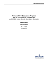
The classic experiment of introducing dye into a flowing stream was first
conducted by Reynolds in 1883. The experiment consists of injecting a small
stream of dye into a flowing liquid and observing the behavior of the dye at
different sections downstream of the injection point. Figure 1-3 shows the
three possible types of flow with the dye injected.
ν
cs
μ
cp
36.13ρ
------------------=
ν
cs
μ
cp
ρ
---------=

Reference Manual
00809-0100-1191, Rev CB
May 2006
1-7
Rosemount 485 Annubar
Figure 1-3. Types of Flow
Development
Average Velocity Unless it is stated otherwise, the term velocity will refer to the average velocity
in the pipe. The average velocity is determined by the continuity equation for
steady state flow.
W = ρAV
This equation states that for steady state flow, the mass rate of flow lbm/sec
(kg/s) at any point in the pipeline can be calculated from the product of the
density lbm/ft
3
(kg/m
3
), the cross-sectional area of the pipe ft
2
(m
2
), and the
average velocity ft/s (m/s).
Laminar occurs when the velocity is small and the dye remains in a straight
line.
Transition occurs at a slightly higher velocity than laminar flow. The dye does
not remain in a straight line and does not spread throughout the pipe.
Turbulent occurs at velocities above transition flow. The dye spreads
throughout the pipe as shown below. It is this type of flow which is important
to the general user. Turbulent flow is, by far, the most common type of flow
encountered in pipes.
Dye Filament
Needle
Tan k
Needle
Tank
Dye Filament
Needle
Tank
Dye Filament
lbm
s
----------
⎝⎠
⎛⎞
lbm
ft
3
----------
⎝⎠
⎛⎞
ft
2
()
ft
s
---
⎝⎠
⎛⎞
=
kg
s
------
⎝⎠
⎛⎞
kg
m
3
-------
⎝⎠
⎛⎞
m
2
()
m
s
---- -
⎝⎠
⎛⎞
=

Reference Manual
00809-0100-1191, Rev CB
May 2006
Rosemount 485 Annubar
1-8
Reynolds Number The work that Osborne Reynolds accomplished in the late 1800's led to a flow
parameter that now carries his name, e.g. the Reynolds Number. His work
showed that the nature of flow in a pipe depends on the pipe diameter (D), the
density (ρ), viscosity, and the velocity of the fluid.
As can be seen, the Reynolds Number has no dimensions and it may be
considered as the ratio of dynamic forces to viscous forces.
For the three types of flow previously discussed, it has been found that
generally laminar flow exists below a Reynolds Number of 2000. Transition
flow generally exists between a Reynolds Number range of 2000 to 4000.
However, the values of 2000 and 4000 are not precisely fixed. The laminar
flow range can terminate between a Reynolds Number range of 1200 to
13000 depending on the smoothness of the pipe. If heat is added to the pipe,
laminar flow can be extended to even higher Reynolds Numbers. The
turbulent flow exist above pipe Reynolds numbers from 4,000 to 13,000.
Since the product is dimensionless, the numerical value will be the same for
any given set of conditions, so long as all the separate factors are expressed
in a consistent system of units. This makes the Reynolds Number an ideal
correlating parameter. Therefore, the flow coefficient of flow meters are
generally expressed as functions of Reynolds Number.
Although the combination DVρ / µ is the classical expression for the Reynolds
Number, there are several other equivalent combinations. First, the ratio ρ/ µ
may be replaced by 1 /υ giving:
Also, the volume rate of flow (ft
3
/s or m
3
/s) is Q = π(D
2
/4)V, thus another
alternate combination for Reynolds Number is:
Also, the mass rate of flow (lbm/s or kg/s) is W = Qρ so that a third alternate
combination is:
If the viscosity (µ) is given in centipoise, the last combination for Reynolds
Number becomes:
The pipe Reynolds Number (R
D
) can be calculated by using any of the
following equations:
Liquid:
R
D
Dνρ
μ
-----------
ft()
ft
s
---
⎝⎠
⎛⎞
lbm
ft
3
----------
⎝⎠
⎛⎞
lbm
ft s⋅
-----------
⎝⎠
⎛⎞
-----------------------------------==
R
D
Dνρ
μ
-----------
m()
m
s
---- -
⎝⎠
⎛⎞
kg
m
3
-------
⎝⎠
⎛⎞
kg
ms⋅
------------
⎝⎠
⎛⎞
---------------------------------- -==
R
D
DV
υ
--------=
R
D
4Qρ
πD
ft
μ
---------------= R
D
4Qρ
πD
m
μ
----------------=
R
D
4W
πD
ft
μ
---------------= R
D
4W
πD
m
μ
----------------=
R
D
1895W
D
ft
μ
cp
-------------------= R
D
1298W
D
m
μ
cp
-------------------=
R
D
3160 GPM G⋅⋅
D μ
cp
⋅
-----------------------------------------= R
D
21230 LPM G⋅⋅
D μ
cp
⋅
-------------------------------------------=

Reference Manual
00809-0100-1191, Rev CB
May 2006
1-9
Rosemount 485 Annubar
Gas:
Liquid, Gas and Steam:
where:
G = specific gravity of flowing fluid (air = 1.0, water = 1.0)
GPM = U.S. gallons per minute
kg/hr = flowrate of fluid in kilograms per hour
LPM = flowrate of fluid in liters per minute
NCMH = flowrate of gas in normal cubic meters per hour
SCFH = flowrate of gas in standard cubic feet per hour
Bernoulli's Theorem Bernoulli's Theorem is a means of expressing the application of The Law of
Conservation of Energy to the flow of fluids in a pipe. The total energy at any
location in the pipe, above some arbitrary datum, is equal to the sum of the
elevation head, the velocity head, and the pressure head.
Figure 1-4. Bernoulli's Theorem
In a steady incompressible flow, without friction, the sum of the velocity head,
pressure head, and elevation head is a constant along any streamline (see
Figure 1-4). Assuming that the elevation difference between two measuring
points is negligible (Z
1
= Z
2
), Bernoulli's Equation can then be written:
Equation 1-1.
where,
V = velocity, ft/s (m/s)
g = gravitation constant, ft/s
2
(m/s
2
)
P = pressure, lbf/ft
2
(kPa)
ρ = density, lbm/ft
3
(kg/m
3
)
A = area, ft
2
(m
2
)
R
D
0.4831 SCFH G⋅⋅
D μ
cp
⋅
-------------------------------------------------= R
D
432 NCMH G⋅⋅
D μ
cp
⋅
------------------------------------------ -=
R
D
6.316
lbm
hr
----------
⎝⎠
⎛⎞
⋅
D μ
cp
⋅
-----------------------------------= R
D
353.6
kg
hr
------
⎝⎠
⎛⎞
⋅
D μ
cp
⋅
------------------------------- -=
Arbitrary Datum Plane
Flow
Constant Energy Line
Z
2
P
2
/ρ
Z
1
V
2
2
/2g
V
2
2
/2g
P
1
/ρ
12
V
1
2
2g
---------
⎝⎠
⎜⎟
⎛⎞
P
1
ρ
------
⎝⎠
⎛⎞
+
V
2
2
2g
---------
⎝⎠
⎜⎟
⎛⎞
P
2
ρ
------
⎝⎠
⎛⎞
+=

Reference Manual
00809-0100-1191, Rev CB
May 2006
Rosemount 485 Annubar
1-10
Since Bernoulli's Theorem states that the flow is steady, the continuity
equation must apply. The continuity equation states that the mass rate of flow
between two points must be constant.
Equation 1-2.
since the flow is incompressible (ρ
1
= ρ
2
), Equation 1-3 reduces to:
Equation 1-3.
solving for V
1
in Equation 1-4:
Equation 1-4.
and substituting into Equation 1-1:
Again, using the continuity equation, the theoretical mass rate of flow would
be:
Equation 1-5.
The theoretical equation for volumetric flow is:
Equation 1-6.
ρ
1
A
1
V
1
ρ
2
A
2
V
2
=
A
1
V
1
A
2
V
2
=
V
1
A
2
V
2
A
1
--------------=
1
2g
------ -
A
2
V
2
A
1
--------------
⎝⎠
⎜⎟
⎛⎞
2
P
1
ρ
------
⎝⎠
⎛⎞
+
V
2
2
2g
---------
⎝⎠
⎜⎟
⎛⎞
P
2
ρ
------
⎝⎠
⎛⎞
+=
V
2
2
2g
------ -
1
2g
------ -
A
2
V
2
A
1
--------------
⎝⎠
⎜⎟
⎛⎞
2
P
1
ρ
------
⎝⎠
⎛⎞
P
2
ρ
------
⎝⎠
⎛⎞
+=–
V
2
2
2g
------ - 1
A
2
A
1
------
⎝⎠
⎜⎟
⎛⎞
2
–
⎝⎠
⎜⎟
⎛⎞
–
P
1
P
2
–
ρ
-------------------=
V
2
2
2g
P
1
P
2
–
ρ
-------------------
⎝⎠
⎛⎞
1
1
A
2
A
1
------
⎝⎠
⎜⎟
⎛⎞
2
–
------------------------=
V
2
2g
P
1
P
2
–
ρ
-------------------
1
1
A
2
A
1
------
⎝⎠
⎜⎟
⎛⎞
2
–
------------------------=
W
theo
ρA
2
V=
2
A
2
2gρ P
1
P
2
–()
1
1
A
2
A
1
------
⎝⎠
⎜⎟
⎛⎞
2
–
------------------------=
Q
theo
A
2
V=
2
A
2
2gρ P
1
P
2
–()
ρ
----------------------------------- -
1
1
A
2
A
1
------
⎝⎠
⎜⎟
⎛⎞
2
–
------------------------=

Reference Manual
00809-0100-1191, Rev CB
May 2006
1-11
Rosemount 485 Annubar
By definition the discharge coefficient of a flow meter is the ratio of the actual
rate of flow to the theoretical rate of flow.
Equation 1-7.
Therefore, the actual volumetric flow for liquid is:
Equation 1-8.
By defining the flow coefficient K of an Annubar primary element as:
The volumetric flow Equation 1-8 reduces to:
Equation 1-9.
In a like manner, the mass rate of flow reduces to:
Equation 1-10.
By using consistent units Equation 1-9 can be checked as follows:
Likewise, Equation 1-10 is:
NOTE:
In the above units conversion, lbf is set equal to lbm. This is only true at
standard gravity (g
c
= 32.174 ft/sec2). However, for measurements on the
surface of the earth, the assumption of lbf = lbm is fairly good.
It is also interesting to note that this assumption leads to the historical name
“head-type meters”. By using the following:
Where h is feet (meters) of head of flowing fluid, equation (2-9) can be written
as:
C
W
actual
W
theoretical
------------------------------- -
Q
actual
Q
theoretical
------------------------------ -==
Q
actual
QA
2
C==
2gρ P
1
P
2
–()
ρ
----------------------------------- -
1
1
A
2
A
1
------
⎝⎠
⎜⎟
⎛⎞
2
–
------------------------
K
C
1
A
2
A
1
------
⎝⎠
⎜⎟
⎛⎞
2
–
---------------------------- -=
QKA
2
=
2g P
1
P
2
–()
ρ
--------------------------------
W
actual
WKA
2
== 2gρ P
1
P
2
–()
Qft
2
=
ft
lbf
ft
2
-------
⎝⎠
⎛⎞
s
2
lbf
ft
3
-------
⎝⎠
⎛⎞
-------------------
ft
3
s
------=
Qm
2
=
m()
kgf
m
2
--------
⎝⎠
⎛⎞
s
2
kgf
m
3
--------
⎝⎠
⎛⎞
------------------------
m
3
s
-------=
Wft
2
=
ft
s
2
-----
lbm
ft
3
----------
lbf
ft
2
-------
lbm
s
----------= Wm
2
=
m
s
2
-----
kgm
m
3
------------
kgf
m
2
--------
kgm
s
------------=
h
lbf
ft
2
-------
lbm
ft
3
----------
---------- ft== h
kgf
m
2
--------
kgm
m
3
------------
------------ m==
QKA2g
lbf
ft
2
-------
⎝⎠
⎛⎞
lbm
ft
3
----------
⎝⎠
⎛⎞
---------------- KA 2gh==
QKA2g
kgf
m
2
--------
⎝⎠
⎛⎞
kgm
m
3
------------
⎝⎠
⎛⎞
----------------- KA 2gh==

Reference Manual
00809-0100-1191, Rev CB
May 2006
Rosemount 485 Annubar
1-12
The equation will be recognized as the well known hydraulic
equation for liquids.
Actual and Standard
Volumetric Flowrate for
Gases
The most common unit of volumetric measurement in English Units is the
cubic foot. The most common unit in SI units is the cubic meter. Many others
exist, such as the cubic inch, the gallon (231 cubic inches), and the barrel (42
gallons); but these are generally defined as portions of a cubic foot.
In Equation 1-9 the volumetric flow (Q) can be calculated in ft
3
/s (m
3
/s) if all
the other parameters have the consistent set of units shown. The most
important aspect of this equation is that the volumetric flow is given in actual
units.
Example:
Suppose a flowmeter is operating according to Equation 1-10, and that the
equation shows that the flowrate is 5 ft
3
/s. Also suppose that the fluid can
be poured or dumped into one (1) cubic foot containers. At the end of one
second, five containers would be full of fluid. In other words, the equation
gave the flowrate in actual cubic feet per second.
For gases, especially fuel gases, the cubic foot is still the unit of
measurement. However, a cubic foot of gas has no absolute or comparative
value unless the pressure and temperature of the gas are specified. Common
sense tells us that the amount of matter within a one cubic foot space at a
pressure of 1000 psia is greater than the amount of matter within that space if
the pressure is atmospheric. Since the fuel gas industry is interested in selling
energy, which is the amount of heat that can be generated by that cubic foot
of gas, and that the amount of energy is directly proportional to the number of
molecules (matter) within the cubic foot space, it is easy to see why the
pressure and temperature of the gas are specified.
Since it is the amount of matter (mass) that is required to be measured as the
gas flows along the pipeline, the actual volumetric flowrate terms do not lend
themselves to this task easily.
Example:
Suppose a gas in a pipeline at 140 kPa abs and 5 °C is flowing at 50
actual m
3
/s; it is not obvious that the same amount of matter (mass) would
flow through a pipeline at 5100 kPa abs and 30.8 °C if the flowrate was
1.54 actual m
3
/s.
Because of the inability to compare the amounts of mass of a gas in actual
volumetric terms, the standard volumetric term was developed. The most
common unit of gaseous measurement is the amount of a gas that would be
contained in a one cubic foot enclosure at standard conditions. Standard
conditions can be defined as any combination of temperature and pressure.
Some common standard sets are provided in the table below.
Table 1-2. Standard Conditions
The approximate conversion from actual volumetric flowrate to standard
volumetric flowrate is accomplished by the BOYLES-CHARLES law. These
laws state the following:
QKA2gh=
Temperature Pressure
60 °F 14.73 psia
68 °F 14.73 psia
0 °C 101.393 kPa abs

Reference Manual
00809-0100-1191, Rev CB
May 2006
1-13
Rosemount 485 Annubar
1. If an ideal gas were contained within an enclosure at constant
temperature, the pressure would increase in proportion to the volume
decrease. Example: the pressure would double if the volume was
reduced by half. The equation takes the form of:
Which states that the product of the pressure and volume at one
condition must equal the product of the pressure and volume at any
other condition provided the temperature is the same at both
conditions.
2. Again, if an ideal gas were contained within an enclosure of constant
volume, the pressure would increase in proportion to the absolute
temperature increase. The equation for this process takes the form:
Which states that the ratio of the pressure and temperature at any
one condition must equal the ratio of the pressure and temperature at
any other conditions provided the volume of the container has not
changed.
Both of these laws can be combined to form a single equation:
If, instead of considering actual volumes, the flowrate (actual volume per unit
time) is used, the equation becomes:
Since and where t is a common unit of time (hours, minutes
or seconds).
Now, if P
1
and T
1
are always considered to be at the standard specified
conditions of 14.73 psia and 60°F (101.393 kPa A and 0 °C), the flowrate Q
1
is the standard volumetric flowrate Q
s
.
This equation allows the standard volumetric flowrate (Qs) to be calculated
from any actual volumetric flowrate (QA) where the pressure and temperature
are known.
In an example on page 1-12, two actual volumetric flowrates were given, and
it was stated that the amount of mass flowing was the same. To check this,
the standard volumetric can be calculated for each flowrate:
P
1
V
1
P
2
V
2
=
P
1
T
1
------
P
2
T
2
------=
P
1
V
1
T
1
--------------
P
2
V
2
T
2
--------------=
P
1
Q
1
T
1
-------------- -
P
2
Q
2
T
2
-------------- -=
Q
1
V
1
t
------= Q
2
V
2
t
------=
14.73
Q
s
460 60+
---------------------- -
P
f
Q
A
T
f
460+
---------------------=
101.325
Q
s
273.15 0+
-----------------------------
P
f
Q
A
T
f
273.15+
----------------------------- -=
Q
s
P
f
14.73
-------------- -
460 60+
T
f
460+
---------------------- - Q
A
⋅⋅= Q
s
P
f
101.325
---------------------
273.15 0+
T
f
273.15+
----------------------------- - Q
A
⋅⋅=

Reference Manual
00809-0100-1191, Rev CB
May 2006
Rosemount 485 Annubar
1-14
Flowrate #1:
Flowrate #2
As can be seen, the two actual volumetric flowrates are identical in terms of
standard volumetric flowrates. However, only ideal gases have been
considered so far. Real gases deviate from the Boyles-Charles relationships.
The amount of deviation depends upon pressure, temperature, and type or
composition of the gas. The deviation is known as the compressibility factor of
the gas. For most flow conditions, the conversion to standard volumetric
flowrate using only the Boyles-Charles relationship will be accurate within a
few percent. To be correct, the Boyles-Charles relationship must be modified
as follows:
Where Z is the compressibility factor at each pressure and temperature
condition. This modification leads to the following:
Where:
Z
b
=compressibility factor at base or standard conditions and is generally
considered to be unity (Z
b
=1.000).
Z
f
=compressibility factor at P
f
and T
f
.
More discussion on compressibility factors can be found in “Ideal and Real
Specific Gravity” on page D-1.
Q
A
50
ft
3
s
------=
P
f
20psia=
T
f
40°F=
Q
s
20
14.73
-------------- -
460 60+
460 40+
---------------------- - 50⋅⋅=
Q
A
50
m
3
s
-------=
P
f
140kPaabs=
T
f
5°C=
Q
s
140
101.325
---------------------
273.15 0+
273.15 5+
--------------------------- - 50⋅⋅=
Q
s
70.6SCFS= Q
s
67.8NMCS=
Q
A
1.5
ft
3
s
------=
P
f
750psia=
T
f
102.5°F=
Q
s
750
14.73
-------------- -
460 60+
460 102.5+
------------------------------- 1.5⋅⋅=
Q
A
1.54
m
3
s
-------=
P
f
5100kPaA=
T
f
39.2°C=
Q
s
5100
101.325
---------------------
273.15 0+
273.15 39.2+
------------------------------------ 1.54⋅⋅=
Q
s
70.6SCFS= Q
s
67.8NMCS=
P
1
V
1
Z
a
T
1
--------------
P
2
V
2
Z
f
T
2
--------------=
Q
s
P
f
14.73
-------------- -
460 60+
T
f
---------------------- -
Z
b
Z
f
------ Q
A
⋅⋅⋅= Q
s
P
f
101.325
---------------------
273.15 0+
T
f
--------------------------- -
Z
b
Z
f
------ Q
A
⋅⋅⋅=

Reference Manual
00809-0100-1191, Rev CB
May 2006
1-15
Rosemount 485 Annubar
Actual and Standard
Volumetric Flowrate for
Liquids
In general, liquid flowrates are not converted into standard volumetric
flowrates. They are usually expressed in actual volumetric terms.
However, some industries do convert actual liquid flows to standard liquid
flows. The petroleum industry is probably the largest industry which does
convert its actual volumes to standard volumes. This is done primarily
because that industry is concerned with the selling and buying of energy. The
energy content of a barrel of oil at 1000 °F is less than the energy content of a
barrel of oil at 60 °F because the oil expands with temperature. Since the
energy content is directly proportional to the amount of matter (mass) within
the barrel, the temperature (thermal) expansion is considered.
Industries which convert liquids to standard volumetric flows have generally
established 60 °F as the reference temperature. To convert actual volumetric
flow to standard volumetric flows, the following equation can be used.
Where,
Q
S
= standard volumetric flowrate
Q
A
= actual volumetric flowrate
ρ
A
= density of fluid at actual flowing conditions
ρ
S
= density of fluid at standard or base conditions
As can be seen, the conversion to standard volumetric flow can be
accomplished simply by multiplying the density ratio. One alternate that is
commonly encountered is that the conversion is accomplished by multiplying
by the ratio of the specific gravities. That is:
Where,
G
f
=specific gravity at flowing conditions
G
S
=specific gravity at base conditions
Since specific gravity is defined as the ratio of the density of the fluid to the
density of the fluid to the density of water at 60°F, these conversions are
identical.
Q
s
Q
A
ρ
A
ρ
s
------=
Q
s
Q
A
G
f
G
s
-------=

Reference Manual
00809-0100-1191, Rev CB
May 2006
1-16
Rosemount 485 Annubar
/