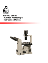
1400INI Series

VAN GUARD 1400INI Series User manual

  • Hello! I've analyzed the Operation Manual for the VanGuard 1400INi Series microscopes, including models 1491INi and 1493INi. This manual provides information about setting up, using, and maintaining your microscope. It also covers features like the trinocular head, ultra-widefield eyepieces, and the coaxial focus controls. I'm ready to answer any questions you have about your device.
  • What is the field diameter of the eyepieces?
    What type of objectives are included?
    What is the magnification of the eyepieces?
    What kind of light source is used?
Operation Manual
Covering Models: 1491INi & 1493INi
1400INi Series
Printed in the USA
VGMNL121916-1490INi
425-823-4518 | 800-423-8842
www.veegee.com/service_support
Vanguard 1400INi Series inverted microscopes
are suited for observation of biological cultures
or specimens within well plates, petri dishes,
slides and vials.
Viewing Head. Rotatable trinocular (Seidentopf)
head is inclined at 30°. All models feature
interpupillary and dioptric adjustment. The trinocular
head features a sliding main prism (80/20 split) to
provide full-time imaging when the vertical tube is
in use (80% of the image to the vertical tube and
20% to the eyetubes).
Eyepieces. 10X ultra-wideeld (DIN) with a eld
diameter of 22mm.
Nosepiece. Quintuple, ball-bearing nosepiece with
high-grade lubricant and positive stops.
Objectives. Plan achromatic, innity corrected
objectives come standard on both models.
Objectives are made to DIN standards and are
optically coated.
Stage. The xed stage measures 160 x 250mm and
300 x 250mm with stage extensions/mechanical
stage attached. Mechanical stage accepts 96
well microplate and included stage inserts:
Terasaki/65mm petri dish, 1 x 3” slide/54mm petri
dish, 35mm petri dish. Motion of mechanical stage
is controlled by a right-hand, low-position coaxial
control and is driven by a rack and pinion system.
Focusing movement. Coaxial, ultra-low position
coarse and ne focus controls feature a 40mm
focusing range and are graduated to 2 microns per
division. Fitted with a tension adjustment.
Condenser. Brighteld models come with a 0.30
N.A. condenser. Phase contrast models come with
a 0.30 N.A. condenser with phase annulus slider
for 10X/20X, and 40X; also has a open setting for
brighteld work. All condensers are factory centered
and aligned for ease of setup and include an iris
diaphragm, and a slide-in lter holder.
Illumination. 30W variable quartz halogen light
source. Comes with blue, green (model 1493INi
only), and dispersion lters. 1A, 250V fuses.
Body. Cast-metal, ergonomic body with stain-
resistant enamel nish.
1400INi Series Inverted Microscopes
Thank you for purchasing this VanGuard microscope. With the user in mind, VanGuard microscopes are built
from modern designs and should provide a lifetime of reliable performance. Before using this microscope it must
be properly setup, which requires some familiarity with the microscope. For this reason we recommend you read
this entire manual carefully before setting up and using the instrument.
Introduction
2
Specifications
19
Viewing Head: Trinocular
Viewing Head Type: Seidentopf
Head Rotation: 360°
Head Inclination: 30°
Sliding Prism: 100% or 80/20% Split
Interpupillary Adjustment: 48-75mm
Dioptric Adjustment: -6 to +6
Eyepiece Magnication: 10X High Eyepoint, Ultra-Wideeld
Eyepiece Field Diameter: 22mm
Nosepiece: Quintuple
Brighteld Objectives: 4X [0.10 N.A., 25.2mm W.D.]
(Plan Achromatic, Innity Corrected) 10X [0.25 N.A., 11mm W.D.]
20X [0.25 N.A., 6mm W.D.]
40X [0.60 N.A., 3.2mm W.D.]
Phase Contrast Objectives: 10X [0.25 N.A., 11mm W.D.]
(Plan Achromatic, Innity Corrected) 20X [0.25 N.A., 6mm W.D.]
40X [0.60 N.A., 3.2mm W.D.]
Stage Dimensions: 160mm x 250mm
Stage Motion: Right-hand Coaxial Control/Rack & Pinion Drive
Stage Movement Range: 78 x 120mm
Sample Clearance (Brighteld): 75mm [Standard]
150mm [With condenser lens removed]
Focusing Movement: Coaxial Coarse & Fine Controls
Focusing Graduation: 2 microns Per Division
Brighteld Condenser (1491INi): 0.30 N.A. Condenser with Iris Diaphragm
Phase Contrast Condenser (1493INi): 0.30 N.A. Condenser with Iris Diaphragm & Annulus Slider
Phase Centering Tool: Telescoping Eyepiece [1493INi only]
Illumination: 30W, 6V Variable Quartz Halogen
Fuse: 1A, 250V (2 ea)
Voltage: 110V [Standard], 220V [Optional]
Base Dimensions: 320mm x 245mm
Overall Dimensions: 515mm (L) x 300mm (W) x 475mm (H)
Weight: 11kg
Table of Contents
Introduction........................................................................ 2
Parts & Accessories
Included Parts........................................................................ 3
Optional Accessories............................................................. 4
Microscope Diagrams......................................................... 5-6
Setup
Assembly........................................................................ 7-12
Using Your 1400INi Microscope
Power Switch/Variable Lighting Control................................. 12
Interpupillary and Diopter Adjustment...................................... 9
Focusing and Mechanical Stage Mechanisms........................ 13
Using the Brighteld/Phase Contrast Condenser.................... 13
Using Filters.......................................................................... 11
Using the Camera Port........................................................... 11
Maintenance
Aligning the Phase Contrast Annulus Rings............................. 10
Replacing the Lamp.............................................................. 14
Replacement lamp Information............................................. 14
Replacing the Fuses.............................................................. 15
Replacement F use Information............................................. 15
Caring for your 1400INi Microscope........................................ 16
Troubleshooting.................................................................... 18
Specications.................................................................. 19
Warranty information and a registration card
can be found at the following web address:
www.veegee.com/service_support
Included Parts:
Parts & Accessories
3
Trinocular Head Assembly 1 ea
Stand 1 ea
Condenser 1 ea
Detachable Slide-Out Filter Holder 1 ea
Phase Contrast Annulus Slider 1 ea
Phase Contrast Centering Telescope 1 ea
Socket Assembly 1 ea
10X High Eyepoint Eyepiece 2 ea
4X Plan, Innity, LWD Objective 1 ea
10X Plan, Innity, Phase, LWD Objective 1 ea
20X Plan, Innity, Phase, LWD Objective 1 ea
40X Plan, Innity, Phase, LWD Objective 1 ea
Terasaki/65mm Petri Dish Stage Insert 1 ea
1 x 3” Slide/54mm Petri Dish Stage Insert 1 ea
35mm Petri Dish Stage Insert 1 ea
Glass Stage Insert 1 ea
Stage Extension 2 ea
Mechanical Stage Assembly 1 ea
Trinocular Port 2 ea
Camera Port 1 ea
Dispersion Filter 1 ea
Blue Filter 1 ea
Green Filter 1 ea
Spare 30W Halogen Lamp 1 ea
Spare 1A Fuses 2 ea
Main Power Cord 1 ea
Focus Tension Wrench 1 ea
Condenser Setscrew Hex Wrench 1 ea
Annulus Centering Hex Wrench 2 ea
Operations Manual 1 ea
Dust Cover 1 ea
Model 1491INi
Troubleshooting
18
Model 1493INi
Trinocular Head Assembly 1 ea
Stand 1 ea
Condenser 1 ea
Detachable Slide-Out Filter Holder 1 ea
Socket Assembly 1 ea
10X High Eyepoint Eyepiece 2 ea
4X Plan Innity LWD Objective 1 ea
10X Plan Innity LWD Objective 1 ea
20X Plan Innity LWD Objective 1 ea
40X Plan Innity LWD Objective 1 ea
Terasaki/65mm Petri Dish Stage Insert 1 ea
1 x 3” Slide/54mm Petri Dish Stage Insert 1 ea
35mm Petri Dish Stage Insert 1 ea
Glass Stage Insert 1 ea
Stage Extension 2 ea
Mechanical Stage Assembly 1 ea
Trinocular Port 2 ea
Camera Port 1 ea
Dispersion Filter 1 ea
Blue Filter 1 ea
Spare 30W, 6V Quartz Halogen Lamp 1 ea
Spare 1A Fuses 2 ea
Main Power Cord 1 ea
Focus Tension Wrench 1 ea
Condenser Setscrew Hex Wrench 1 ea
Operations Manual 1 ea
Dust Cover 1 ea
This chart may help resolve some of the more common problems associated
with using a compound microscope. Simply follow the steps until your problem
is resolved. As always, you can contact your dealer or VanGuard Microscopes
if you ever need help.
All Models
Symptom: Can’t focus on specimen image
Step # Possible Cause How To Test Test Result? Solution For More Info
2
1 Dirty objective Visually inspect
Objective is clean
Objective is not clean
Go to next step
Clean objective or replace with new objective Pages 16 & 4
Specimen vessel is too thick Test with dierent vessel Vessel is correct
Vessel is too thick
Contact dealer or VanGuard Microscopes
Replace with 1.2mm max thickness vessel
Page 18
Symptom: No image visable in eyepiece(s) and/or trinocular port
Step # Possible Cause How To Test Test Result? Solution For More Info
1
5
4
3
2
Light is not switched on Visually inspect Switched on
Not switched on
Go to next step
Move power switch to on position Page 12
Variable lighting control (VLC) is
set too low Visually inspect Not set too low
Set too low
Go to next step
Increase VLC level
Objectives not installed Visually inspect
Objectives are installed
Objectives not installed
Go to next step
Install objectives Page 7
Light path selection knob in wrong
position Visually inspect In correct position
Not in correct position
Go to next step
Set to correct position Page 11
Light path blocked Visually inspect space between
illuminator and objectives Blockage present
Nothing blocking
Remove blockage
Contact dealer or VanGuard Microscopes Page 18
Page 12
For information about parts, accessories, or service -- contact your dealer directly or
contact VanGuard Microscopes at 1-800-423-8842 | [email protected] | www.veegee.com
Parts & Accessories
4
All Models
Troubleshooting
17
This chart may help resolve some of the more common problems associated
with using a compound microscope. Simply follow the steps until your problem
is resolved. As always, you can contact your dealer or VanGuard Microscopes
if you ever need help.
All Models
Symptom: No light visable from collector
Step # Possible Cause How To Test Test Result? Solution For More Info
1
6
5
4
3
2
Light is not switched on Visually inspect Switched on
Not switched on
Go to next step
Move power switch to on position Page 12
Main power cord and/or
illuminator plug not connected Visually inspect Plugged in
Not plugged in
Go to next step
Plug in power cord or illuminator plug
Variable lighting control (VLC)
turned all the way down Visually inspect
VLC turned up
VLC turned down
Go to next step
Turn VLC up Page 12
Microscope not getting power Inspect outlet Good outlet
Outlet not good
Go to next step
Plug power cord into working outlet
Blown fuse Visually inspect or try new fuse Good fuse
Fuse is blown
Go to next step
Install new fuse Page 15
Burnt out light bulb Visually inspect or try new bulb Good bulb
Bulb is burnt out
Contact dealer or VanGuard Microscopes
Install new bulb Page 14
Page 18
Symptom: Image through eyepieces is too dim
Step # Possible Cause How To Test Test Result? Solution For More Info
1
3
2
Variable lighting control (VLC) is
turned down too far Visually inspect VLC is turned up
VLC is turned down
Go to next step
Turn VLC up Page 12
Light bulb not centered properly Visually inspect Bulb is centered
Bulb is not centered
Go to next step
Center the bulb
Light path selection knob in wrong
position (trinocular models only) Visually inspect
Not in correct position
In correct position
Set to correct position
Go to next step
Page 14
Page 11
Symptom: The objectives keep drifting downward
Step # Possible Cause How To Test Test Result? Solution For More Info
1Focus tension is set too loose Check focus tension control
Tension too loose
Tension set correctly
Increase tension
Contact dealer or VanGuard Microscopes Page 18
Page 13
4Dirty condenser, eyepiece, or
objective lenses Visually inspect
Lenses are dirty
Lenses are clean
Clean lenses
Contact dealer or VanGuard Microscopes Page 18
Page 16
Optional Accessories:
Digital & Video Camera Systems:
Part Number Description
1490-CVK CCD Video Camera Kit with Adapters, NTSC Format, 110V*
1400-CDCK DSLR Digital Camera Kit with Adapters and Software
1400-CNC DSLR Digital Camera Adapter Only Kit** (Camera Not Included)
1400-CDPC-x USB Digital Camera Kit with Adapters and Microscopy Software
*CVK video camera kits are also available in 220V NTSC and 220V PAL formats. Please contact us for more information.
**We have a wide range of adapters to t many digital cameras to our microscopes. Please contact us for more information.
Epi-Fluorescence Upgrade Package
Part Number Description
1490-FLP01 Fluorescence upgrade kit with blue/green broadband lter sets
1490-FUV001 Optional eGFP lter set for uorescence upgrade kit
Contact us for Information Optional lter sets for single & multiple dye applications
Other Accessories & Consumables:
Part Number Description
1200-MLCK Cleaning Kit (Cleaning Liquid, Blower Brush, Lens Tissue, and Cotton Swabs)
45000-OT001 VEE GEE Optical Tissue
1200-MSL10 Plain Glass Slides, 1x3”
1200-CS242 Cover Glass, 24x24mm
Contact us for Information Reticles (Grid, Pointer, Crosshair & Scale)
Contact us for Information Stage Micrometers for Calibration of Scale Reticles (Metric and SAE Available)
Contact us for Information Plan Fluorite Objectives
For information about parts, accessories, or service -- contact your dealer directly or
contact VanGuard Microscopes at 1-800-423-8842 | [email protected] | www.veegee.com
Parts & Accessories
516
Model 1493INi Pictured
Maintenance
Caring for your 1400INi Microscope All Models
The eyepieces and objective lenses on VanGuard Microscopes have delicate, optical coatings. Therefore they should
never be wiped while dry because any dirt or dust will scratch the coating. Blow o the lens surface with an air-bulb and
lens brush. Then use a lens cleaning solution. Never use anything other than lens cleaner on any optical component.
Apply with a cotton swab for a minimum of wetting, then wipe the surface clean with a quality lens tissue. These items
are all available in our cleaning kit (see page 4 for ordering information.)
The same care instructions apply to all optical parts on this VanGuard Microscope, including the condenser lenses.
All other parts can be cleaned with a paper towel and mild detergent. Be aware that rubbing alcohol can break down
lubricants and damage the painted surfaces; it is therefore not recommended. If used, be careful when cleaning near
the following parts:
Focus controls
Nosepiece
Mechanical controls
Xylene, since it breaks down the bonding material holding the lenses, should never be used as a cleaner.
Periodically, your VanGuard Microscope should be fully serviced by a qualied service technician.
In order to keep dust and debris out of the optical pathways, always keep the camera port and eyetubes covered (with
either eyepieces or dust caps), and always use the dust cover when the microscope is not in use.
Objectives
Mechanical
Stage
Condenser
Iris Diaphragm
Control
Slide-out Filter
Holder
Eyepieces
Diopter
Adjustment
Coarse Focus
Control
Trinocular
Port
Interpupillary
Adjustment
Lamp Socket
Assembly
Stand
Nosepiece
Trinocular Port
Dust Cover
Fine Focus
Control
Head Assembly
Condenser
Condenser
Lens
Condenser
Set Screws
Phase Contrast
Annulus Slider
Variable
Lighting
Control
For information about parts, accessories, or service -- contact your dealer directly or
contact VanGuard Microscopes at 1-800-423-8842 | [email protected] | www.veegee.com
Parts & Accessories
6
Maintenance
15
Power Switch
X-Y Stage
Controls
Interpupillary
Scale
Head Set
Screw
Focus Tension
Control
Trinocular Port
Set Screw
Light Path
Selection
Knob
Model 1493INi Pictured
1. Remove the fuse holders from the rear of the microscope (gure 27) by
using a slotted screwdriver to push inward while turning counter-clockwise.
2. Remove the fuse from the fuse holder.
3. If the fuse is blown replace by inserting a new fuse into the fuse holder (gure
28).
4. Thread the fuse holder back into the microscope by turning in a clockwise
direction with the slotted screwdriver.
Replacing the Fuses All Models
Before attempting to replace or remove the fuse,
UNPLUG THE MICROSCOPE FROM ANY POWER
SOURCE. !
Replacement Fuse - 2 each 1A 250V (Cat. No. 1200-FS4)
Figure 28
Figure 27
If the microscope is plugged in but the bulb is not turning on, the fuses could
be blown. The instructions below detail how to check for a blown fuse. You
can tell a blown fuse by if the wire inside is broken, or the glass is blackened.
For information about parts, accessories, or service -- contact your dealer directly or
contact VanGuard Microscopes at 1-800-423-8842 | [email protected] | www.veegee.com
Setup
1. Remove all components from the packaging. Use the parts list on page 3
to verify that all parts are present. Please retain all packaging in the unlikely
event that the instrument should need servicing in the future.
2. Place the stand on a stable counter top.
3. Remove the plastic protective cover from the bottom of the head assembly.
4. Loosen the head set knob (gure 1).
5. Remove the protective cover from the head mount on the stand.
Basic Assembly
6. Place the head assembly on top of the stand so that the dovetail ange
slides into place.
7. Secure by tightening the head set screw.
7
All Models
Do not release the head assembly until it is rmly
secured to the microscope with the head set screw.
Maintenance
14
8. Remove the dust caps from the eyetubes.
9. Insert the eyepieces into the eyetubes (gure 2).
10. Remove the objectives from their storage containers.
11. Unthread four of the protective covers from the nosepiece.
12. Install the objectives onto the nosepiece by threading them clockwise
into the holes until they are fully seated (gure 3). Be careful not to cross
thread. It is common practice to install the objectives in order of increasing
magnication, though not required.
Figure 1
Figure 2
Figure 3
1. Remove the socket assembly from the top of the condenser (gure 25).
2. Remove the lamp from the socket by gently pulling.
Replacing the Lamp
3. When replacing, insert the new lamp into the socket assembly. Make sure
that the pins on the lamp line up with the holes on the socket. The pins
should slide freely into the holes with only slight resistance - do not force.
4. The lamp lament should be lined up with the screw head located underneath
the lamp for proper centering (gure 26).
5. Replace the socket assembly.
All Models
Before attempting to replace or remove the lamp,
UNPLUG THE MICROSCOPE FROM ANY POWER
SOURCE and allow to cool. !
Be careful not to touch the glass bulb when replacing
- use a tissue or other medium to grasp the lamp.
This will prevent the oils in your hand from reducing
lamp life. If contact is made with the bulb, clean with
rubbing alcohol and allow a brief drying period.
!
Figure 25
Replacement Lamp - 30W, 6V Halogen (Cat. No. 1400-30WHL)
Figure 26
set knob
For information about parts, accessories, or service -- contact your dealer directly or
contact VanGuard Microscopes at 1-800-423-8842 | [email protected] | www.veegee.com
Setup
13. Slightly loosen the two condenser set screws in the condenser mount with
the included hex key and insert the condenser into the mount.
Model 1491INi only: It will be necessary to remove the condenser plug
while inserting the condenser into the condenser mount.
14. Rotate the condenser clockwise until the “AS” mark faces forward.
15. Secure in place by retightening the condenser set screws.
Basic Assembly (continued)
8
All Models
Figure 5
Figure 4
13
16. Model 1491INi only: Replace the condenser plug into the condenser.
Figure 7
Figure 6
17. Model 1493INi only: Slide the phase annulus slider into the condenser
assembly, printed side up.
18. Slide the illuminator power plug onto the two prongs located on the socket
assembly
19. Place the socket assembly onto the condenser so that the large location pins
slide into the pin slots and push down gently until housing is fully seated.
1. Focusing adjustment is achieved by turning the coarse/ne focus controls
located on both sides of the microscope (gures 21 and 22). The large knob
is used for coarse adjustment, the smaller knob for ne adjustment. The
coaxial arrangement allows for easy, precise adjustment without drift.
2. Turning the coarse/ne focus control raises and lowers the nosepiece
vertically. One complete turn of the ne focusing knob raises or lowers the
nosepiece 0.3mm; the smallest graduation refers to 2 microns of vertical
movement. One complete turn of the coarse focusing knob raises or lowers
the nosepiece 3.6mm. To ensure long life, turn the focusing knobs slowly
and uniformly.
3. The focusing tension control knob is located just inside of the right-hand focus
control knob (see arrow in gure 21). For tighter tension, use the included
tension adjustment wrench and turn the control knob in a clockwise motion.
For looser tension, turn the control knob in a counterclockwise motion.
4. The mechanical stage X-Y controls, located underneath the right-hand side
of the stage (gure 23), provide easy and accurate positioning of the sample.
One complete turn of the longitudinal (Y) control (lower half of the stage
controls, bottom arrow) will move the specimen 34mm left or right. One
complete turn of the transverse (X) control (upper half of the stage controls,
top arrow) will move the specimen 20mm front or back.
5. This microscope comes with various stage inserts:
Terasaki/65mm Petri Dish Stage Insert
1 x 3” Slide/54mm Petri Dish Stage Insert
35mm Petri Dish Stage Insert
Glass Stage Insert
Focusing and Mechanical Stage Mechanisms All Models
Figure 21
Figure 23
Figure 24
Figure 22
Brighteld and Phase Contrast Condensers
1. Aperture Adjustment: The light path can be adjusted with the iris diaphragm
adjustment lever (see arrow in gure 24) located in the condenser. The
aperture diaphragm acts as a control for resolution and contrast. Generally, if
the iris diaphragm is open too far, you will have high contrast at the expense
of resolution. If the iris is closed too far, you will not have enough contrast
to properly view the specimen. The condenser iris diaphragm should not be
used to adjust light intensity, which is best left to the variable lighting control.
2. Annulus Slider (phase contrast condenser only): When using phase contrast
the number on the annulus slider must match the magnication of the
objective in use. For example, if you are using the 10X objective, slide the
annulus turret until it reads “10-20”. For brighteld work set the annulus
slider to the open position.
Microscope Use
Setup
912
Figure 9
21. Connect the main power cord to the power cord jack (gure 9) on the back
of the microscope.
22. Connect the other end of the main power cord to a suitable power supply.
23. Power on the microscope using the power switch located on the right hand
side of the microscope.
24. Set illuminator to desired intensity by adjusting the variable lighting control
located at the front of the microscope.
20. Place the glass stage plate into the opening in the stage. This plate allows
the user to easily view the objectives.
Figure 8
Interpupillary and Diopter Adjustment
Interpupillary adjustment (the distance between eyepieces) is made through a
“folding” action. The Seidentopf design allows for a folding adjustment which is
quickly and easily done for each user (gure 10).
Proper adjustment is done by looking through the eyepieces, then “folding” the
eyepieces until they are comfortable to look through. At this point, if you are
seeing two images continue to “fold” the eyepieces together until the images
merge into one.
Figure 11
Figure 10
1. Using the 40X objective and a sample slide (i.e. one which produces an
easily focused image), close your left eye and bring the image into focus in
your right eye with the coarse/ne focus control.
2. Once the image is well-focused using only your right eye, close your right
eye and check the focus with your left.
3. If the image is not perfectly focused, make ne adjustments with the diopter
adjustment mechanism located on the left eyetube (see arrow in gure 11).
4. Once complete, the microscope is corrected for your vision.
Diopter adjustment allows for proper optical correction based on each individual’s
eyesight. This adjustment is easily made and is recommended prior to each use
by dierent users to prevent eyestrain. The procedure for dioptric adjustment
is as follows:
All Models
Figure 19
Removal of Condenser Lens
1. The condenser lens may be removed in order to gain additional sample
clearance space when viewing specimens in large vessels. By unscrewing
the lens (gure 19) the sample clearance is extended from 75mm to 150mm.
Power Switch/Variable Lighting Control
The rocker switch located on the right hand side of the microscope ( see lower
arrow in gure 20) turns the illuminator on or o. To turn the power on press
the rocker on the end marked “|”. To turn the power o press the rocker on the
end marked “O”.
All Models
Figure 20
The illuminator housing will get hot if left on for
extended periods of time. Be careful when making
adjustments to the illuminator housing or bulb xture. !
VanGuard 1490INi microscopes are equipped with a variable lighting control
(VLC), which allows the user to set the lighting anywhere between o and full
brightness. The variable lighting control is located on the front of the microscope
(see upper arrow in gure 20). To increase the brightness rotate the wheel
clockwise.
Setup
Optional Setup (cont.) All Models
main power
cord jack
Setup
10 11
Optional Setup All Models
Stage extensions and mechanical stage assembly:
1. Either one or both of the included stage extensions can be attached at the
same time on opposite sides of the stage to increase the stage size when
using large specimen holders. In addition, the mechanical stage can be
attached to either side of the stage in place of an extension.
2. Hold the extension or mechanical stage against the side of the stage and
position the screws underneath the screw holes (gure 15). Thread the
screws into the screw holes and tighten down until the attachment is secure.
Figure 15
This section pertains to model 1493INi only!
The phase system comes precentered from the factory but alignment should be
checked from time to time especially if poor phase performance has been noted.
1. Power on the microscope and rotate the objective turret until the 10X
objective is in the light path. Make sure the condenser iris is fully opened.
2. Place a specimen on the stage and focus the image using the coaxial focus
controls.
3. Remove the right eyepiece and insert the centering telescope into the empty
eyetube (gure 12).
4. Adjust the phase annulus slider to the “10-20” position.
5. While looking through the centering telescope, turn the uppermost portion
of the telescope only to focus the annulus rings (gure 12).
6. Insert the annulus centering hex keys into the the adjustment holes on the
phase annulus slider (gure 13). Turn the hex keys until the two phase rings
visable in the centering telescope are centered over one another (gure
14A-14B). Repeat this step for the 40X objective and “40” annulus setting.
Phase Contrast Setup Model 1493INi
Figure 12
Figure 13
Figure 14BFigure 14A
Figure 17
Trinocular Port
The trinocular port can be used as an additional viewing tube when a standard
23mm eyepiece is inserted (not included) as well as to attach a camera for
documentation and group observation.
1. Loosen the trinocular port set screw (see upper arrow in gure 17) and
remove the trinocular port dust cap.
2. Slide the trinocular tube assembly into the trinocular port (gure 18) and
secure with the trinocular port set screw. Be sure the trinocular tube is
inserted fully into the trinocular port.
3. For attaching an eyepiece simply remove the trinocular tube dust cap and
insert a 23mm eyepiece. For attaching a camera follow the instructions
provided with the camera package for assembly and use.
Note: When using the trinocular port it is necessary to pull the light path selection
knob fully to the right (see lower arrow in gure 17). This diverts 80% of the
available light to the trinocular tube while the remaining 20% is directed to the
main eyepieces. When pushed inward fully, the selector directs 100% of the
light to the main eyepieces for the brightest speciman viewing possible.
Dispersion lters can be used to soften harsh illumination for both viewing and
photomicroscopy. Dispersion lters can control photograph exposure levels.
The green lter is used primarily for phase contrast and photograph color
correction. Achromatic and plan achromatic objectives give their best image
in green light.
The blue lter is used to approximate natural light. Because this is not a
conversion lter, it should not be used for photomicroscopy.
Filtering is a user preference and application specic issue and therefore
beyond the scope of this manual. There are many sources available that explain
proper ltering technique and theory.
Figure 18
Figure 16
Colored Filters
Your Vanguard Microscope was supplied with either two or three lters.
Brighteld models (1491INi) come with a dispersion (frosted) lter and a blue
lter. Phase contrast models (1493INi) add a green lter.
1. Slide out the lter holder (see arrow in gure 16) and place the desired lter
into the bottom of the holder making sure that it sits at. Replace lter holder.
2. You may stack lters but the total thickness should not exceed 11mm.
Setup
Optional Setup (cont.) All Models
trinocular
port
set screw
trinocular port
assembly
/