Page is loading ...

Installation Guide
IND150
Lumination® Assent LBR & LBT
Recessed LED Troers
BEFORE YOU BEGIN
Read these instructions completely and carefully.
WARNING/AVERTISSEMENT
RISK OF ELECTRIC SHOCK
• Turn power o before inspection, installation or removal.
• Properly ground electrical enclosure.
RISK OF FIRE
• Follow all NEC and local codes.
• Use only UL approved wire for input/output connections.
Minimum size 18 AWG (0.75mm2).
RISQUES DE DÉCHARGES ÉLECTRIQUES
• Coupez l’alimentation avant d’inspecter, installer ou déplacer le luminaire.
• Assurez-vous de correctement mettre à la terre le boîtier d’alimentation
électrique.
RISK OF FIRE
• Respectez tous les codes NEC et codes locaux.
• N’utilisez que des ls approuvés par UL pour les entrées/sorties de
connexion. Taille minimum 18 AWG (0.75mm2).
Save These Instructions
Use only in the manner intended by the manufacturer.
If you have any questions, contact the manufacturer.
Prepare Electrical Wiring
Electrical Requirements
• The LED luminaire must be connected to the mains supply
according to its ratings on the product label.
• Class 1 wiring should be in accordance with NEC.
Grounding Instructions
• The grounding and bonding of the overall system shall be
done in accordance to local electric code of the country where
the luminaire is installed.
Components Supplied
• Luminaire
Tools and Components Required
• Slot or Philips screwdriver
• UL Listed conduit connections per NEC/CEC for nominal
conduit trade sizes ½” or ¾”
• UL Listed wire connectors

2
Assent, LBT & LBR Installation Guide
Carefully unpack unit from its packaging. Properly inspect
for defects before installing. Wear work gloves to prevent
dirt and oil from being transferred to the luminaire.
1
Luminaire Installation
Install the unit into the reserved hole in the ceiling.
2
Bend the 4 clips to secure the luminaire in place. Install
the safety cables through the holes on the clips (per local
building codes, safety cables by others).
NOTE: Dimming leads for
the VQ and V1 catlogic
option are 0-10V dimming,
grey/pink (-), violet (+).
Dimming leads for the
LE option are Lutron
Ecosystem - grey/pink is E1
(-), violet is E2 (+).
3
WARNING/AVERTISSEMENT
Risk of electrical shock. Disconnect power before servicing or installing product.
Risque de choc électrique. Couper l’alimentation avant le dépannage ou avant l’installation du produit.
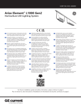
Electrical Connections
120-277V
WHITE COMMON
NEUTRAL
BLACK UNSWITCHED
LINE
GROUND GROUND
GREY DIMMING
0-10V
DIMMING (••)
VIOLET DIMMING (+)
Exterior Wires
Exterior Wires
Back-Lit Recessed Troffer Module
Back-Lit Recessed Troffer Module
347V
RED COMMON
NEUTRAL 347V
BLACK UNSWITCHED
LINE 347V
GROUND GROUND
GREY DIMMING
0-10V
DIMMING (••)
VIOLET DIMMING (+)
Bend clips
Safety cable
120-277V
WHITE COMMON
NEUTRAL
BLACK UNSWITCHED
LINE
GROUND GROUND
GREY DIMMING
0-10V
DIMMING (••)
VIOLET DIMMING (+)
Exterior Wires
Exterior Wires
Back-Lit Recessed Troffer Module
Back-Lit Recessed Troffer Module
347V
RED COMMON
NEUTRAL 347V
BLACK UNSWITCHED
LINE 347V
GROUND GROUND
GREY DIMMING
0-10V
DIMMING (••)
VIOLET DIMMING (+)
(-)
(-)GREY/PINK GREY/PINK

3
Assent, LBT & LBR Installation Guide
Remove electrical enclosure cover. Remove knockout for
AC line input wires.
1
AC line
Install listed electrical ttings in the knockout holes for
wire protection. Connect the AC line to the luminaire
internal wires according to the wiring diagrams using 18-
14AWG twist-on wire connectors.
2
Install listed electrical ttings in the knockout holes for
wire protection. Connect the dimming control (grey/pink
and purple) wires of the LED driver using 18-14AWG twist-
on wire connectors.
3
Alternative Wiring From Below the Ceiling (for LBR Version Only)
Dimming line
Replace electrical enclosure cover and secure it with the
screw.
4
Swing down panel and lift o front bezel.
1
Remove screw
Unfasten screw holding driver plate. Grab tab and shift
plate to the left and pull outward.
2

www.gecurrent.com
© 2021 Current Lighting Solutions, LLC. All rights reserved. GE and the GE monogram are trademarks of the
General Electric Company and are used under license. Information provided is subject to change without
notice. All values are design or typical values when measured under laboratory conditions.
IND150 | DOC-2002191 (1/10/22)
Assent, LBT & LBR Installation Guide
This device complies with Part 15 of the FCC Rules. Operation is subject to the following two conditions: (1) This device may not cause
harmful interference, and (2) this device must accept any interference received, including interference that may cause undesired operation.
CAN ICES-005 (A) / NMB-005 (A)
Note: This equipment has been tested and found to comply with the limits for a Class A digital device, pursuant to part 15 of the FCC
Rules. These limits are designed to provide reasonable protection against harmful interference when the equipment is operated in a
commercial environment. This equipment generates, uses, and can radiate radio frequency energy and, if not installed and used in
accordance with the instruction manual, may cause harmful interference to radio communications. Operation of this equipment in
a residential area is likely to cause harmful interference in which case the user will be required to correct the interference at his own
expense.
Note: CONTACT FACTORY for details and limitations when seeking to incorporate this product with an emergency system other than
Battery Backup.
Remove driver plate. Driver is attached to cover plate and
wiring is accessible when cover plate is removed. Connect
the AC line to the luminaire internal wires according
to the wiring diagrams using 18-14AWG twist-on wire
connectors. Connect the dimming control (grey/pink and
purple) wires of the LED driver using
18-14AWG twist-on wire connectors.Install listed electrical
ttings in the knockout holes for wire protection as well
as lead wires into the electrical cavity.
3
Fasten screw
Push plate into opening and shift to the right. Fasten
screw of driver plate to the housing.
4
Hang panel on its hinges and swing up into place.
5
Rotate latches to lock the front bezel.
6
/