Page is loading ...

D
E
S
I
G
N
P
A
T
E
N
T
E
D
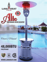
UP TO 8 HRS
RUN TIME
WEIGHTED BASE
AUTOMATIC
ELECTRONIC
IGNITION
TILT SWITCH
AUTO-SHUTOFF
OWNER'S MANUAL
PROPANE POWERED
WWW.LAVAHEAT.COM
OVERHEAD PATIO HEATER
5
YEAR
L
I
M
I
T
E
D
W
A
R
R
A
N
T
Y

1
Owner’s Manual
Questions, problems, missing / replacement parts? Before returning to your retailer, call
our customer service department at 1.888.779.5282, Monday-Friday 9 a.m.-6:00 p.m.
PST, or email [email protected]
Sorrento
If you smell gas:
1. Shut off gas to the appliance.
2. Extinguish any open flame.
3. If odor continues, keep away from the appliance and
immediately call you gas supplier or fire department.
WARNING
Do not store or use gasoline or other flammable vapors
and liquids in the vicinity of this or any other appliance.
An LP-cylinder not connected for use shall not be stored
in the vicinity of this or any other appliance
CAUTION:
Installer: Leave the manual instructions
to the user for future use.
Consumer: Please keep this manual for
future reference.
Read the instructions before use.
This appliance must be installed in
accordance with such regulations
as are in force.
MODEL: SORRENTO
FOR OUTDOOR USE ONLY
WARNING
WARNING
OVERHEAD PATIO HEATER

2
This appliance can produce carbon monoxide
which has no odor.
Using it in an enclosed space can kill you.
Never use this appliance in an enclosed space such
as a camper, tent or home.
DANGER
CARBON MONOXIDE HAZARD
WARNING: Improper installation, adjustment, alteration, service or
maintenance can cause property damage, injury or death. Read the installation, operating
and maintenance instructions thoroughly before installing or servicing this equipment.
WARNINGS AND CAUTIONS
SPECIFICATION
Certification C
74” x 31.5” x 93.7” (1880x800x2380mm)
SA
Product size
Rated heat input 32,000 BTU/hr
Fuel LP
Gas Supply 20 lb (9 kg) LP gas cylinder
Manifold pressure 3PSI
Diameter of injector 0.039" (0.99 mm)
Safety features Flame failure device, anti-tilt switch
G
Battery Size D 2pcs
as supply pressure Max. 250 PSI, Min. 5 PSI

3
WARNINGSANDCAUTIONS
The installation must conform with local codes
or, in the absence of local codes, with the
NationalFuelGasCode,ANSIZ223.1/NFPA54,
NFPA58 Natural Gas and Propane Installation
Code, CSA B149.1, or Propane Storage and
HandlingCode,B149.2
Theheater,wheninstalled,mustbeelectrically
groundedin accordancewith localcodesor,in
the absence of local codes, with the National
ElectricalCode,ANSI/NFPA70,ortheCanadian
ElectricalCode,CSAC22.1.
Childrenandadultsshouldbealertedto
thehazardsofhighsurfacetemperatures
and should stayawaytoavoidburnsor
clothingignition.
Young children should be carefully
supervised when they are in the area of
theheater.
Clothing or other flammable materials
should not be hung from the heater, or
placedonorneartheheater.
Priorto use,check fordamaged partssuchas
hoses,regulators,pilotorburner.
Allleaktestsshouldbedonewithasoapysolu
tion. NEVER USE AN OPEN FLAME TO
CHECKFORLEAKAGE.
Thepropanehosewithregulatorassemblyshall
be located out of pathways where people may
tripoveritorinareaswherethehosewillnotbe
subjecttoaccidentaldamage.
Any guard or other protective device
removedforservicingtheheatermustbe
replacedpriortooperatingtheheater.
Installationandrepairshouldbedoneby
a qualified service person. The heater
should be inspected before use and at
least annually by a qualified service
person.
More frequent cleaning may be required
asnecessary.Itisimperativethatcontrol
compartment,burnersandcirculatingair
passagewaysoftheheaterbekeptclean.
Keepingtheapplianceareaclearandfreefrom
combustiblematerials,gasolineandotherflam
mablevaporsandliquids.
Notobstructingtheflowofcombustionandventi
lationair.
Keeping theventilationopening(s) of the cylin
derenclosurefreeandclearfromdebris.
This appliance shall be used only in a well
ventilatedspaceandshallnotbeusedinabuild
ing,garageoranyotherenclosedarea.
An appliance may be installed with shelter no
moreinclusivethan:
With walls on all sides, but with no overhead
cover.
Within a partial enclosure which includes an
overhead cover and no more than two side
walls.Thesesidewallsmaybeparallel,asina
breezeway,oratrightanglestoeachother.
NOTE:PLEASEREADTHEFOLLOWINGSAFETYRULES
WARNING:

4
WARNINGS AND CAUTIONS
The pressure regulator and hose assembly sup-
plied with the appliance must be used, replace-
ment pressure regulators and hose assemblies
must be those specified by the appliance manu-
facturer.
Do not store a spare LP-gas cylinder under or
near this appliance;
Never fill the cylinder beyond 80 percent full;
Do not clean the heater with cleaners that are
combustible or corrosive.
NOTE:PLEASE READ THE FOLLOWING SAFETY RULES
Place the dust cap on the cylinder valve outlet
whenever the cylinder is not in use. Only install
the type of dust cap on the cylinder valve that is
provided with the cylinder valve. Other types of
caps or plugs may result in leakage of propane.
Within a partial enclosure which includes an
overhead cover and three side walls, as long as
30 percent or more of the horizontal periphery of
the enclosure is permanently open.
This appliance requires 9kg(20lb) LP-gas supply
cylinder.
The LP-gas supply cylinder to be used must be:
Constructed and marked in accordance with the
Specifications for LP-gas cylinders of the U.S.
Department of Transportation (DOT); or the
Standard for Cylinders, Spheres and Tubes for
Transportation of Dangerous Goods and Com-
mission, CAN/CSA-B339, as applicable;
Provided with a listed overfilling prevention
device; and provided with a cylinder connection
device compatible with the connection for the
appliance.
The cylinder be disconnected when the appli-
ance is not in use.
Storage of an appliance indoors is permissible
only if the cylinder is disconnected and removed
from the appliance.
A cylinder must be stored outdoors in a well-
ventilated area out of the reach of children. A
disconnected cylinder must have dust caps
tightly installed and must not be stored in a build-
ing, garage or any other enclosed area.
WARNING:
Certain materials or items, when stored under
the heater, will be subjected to radiant heat and
could be seriously damaged.
Inspect the visible portion of the hose before
each use of the appliance and inspect the entire
hose assembly at lease annually.
The cylinder used must include a collar to protect
the cylinder valve.

Adjustable open end wrench
5
WARNINGS AND CAUTIONS
This heater is designed to operate with a standard 20 Ib propane cylinder with Approved Cylinder
Connection.
NOTE: PLEASE READ THE FOLLOWING SAFETY RULES:
TOOLS NEEDED: (NOT INCLUDED)
Estimated time for assembly: 40 minutes.
Philips screwdriver
PREPARATION
Before beginning assembly of product, make sure all parts are present. If any part is missing or
damaged, do not attempt to assemble the product. Contact customer service for replacement parts.
Please wear protective gloves when assembling this product.
Perform a leak test with a soapy solution:
1. To check gas connections.
2. After connecting a new cylinder.
3. Upon re-assembly after disassembly.

6
EXPLODED VIEW
Please check the contents of the packaging as to whether anything is missing!
1
2
3
4
5
6
7
8
9
10
AA
BB
CC
DD
EE
11

PARTS LIST
7
DescriptionPart #
1 Cover 1
1
1
1
1
1
1
1
Head assembly
Cover fixed plate
Transom control assembly
Transom mounting plate
Decorative cover
Base assembly
Wheel kit
2
3
4
5
7
1
Pole
6
8
9
1
Cylinder fixing hook
10
2(Not included)
1.5V D size battery
11
Qty
AA
BB
DD
EE
CC
6
4
2
8
2
M4 x 10 bolt
4mm washer
M6 nut
M6 x 20 bolt with 6mm
washer and 6mm spring
washer
M6 x 14 bolt
Description PicturePart # Qty
HARDWARE

8
ASSEMBLY INSTRUCTIONS
STEP 1
Attach wheel kit (9) to base assembly (8) with 2pcs
M6 x 20 bolts with 6mm washers and 6mm spring
washers (EE).
Hardware Used
EE 2
M 6 x 20 bolt with
6mm washer and
6mm spring washer
8
9
EE
STEP 2
Open the door of base assembly (8). Half-loosen 2pcs M6 x 20 bolts on pole fixing sleeve and insert the pole (6) into the
pole fixing sleeve, make sure the shoulder screw on pole sit into the slot on pole fixing sleeve. Then tighten 2pcs M6 x 20
bolts on pole fixing sleeve.
Place the decorative cover (7) through pole (6) and on the tabletop.
6
6
M6 x 20 bolt
Pole fixing sleeve
Shoulder screw on pole
Pole fixing sleeve
Table of base assembly (8)
7

9
ASSEMBLY INSTRUCTIONS
STEP 4
Attach head assembly (2) to transom control assembly (4) with 4pcs M6 x 14 bolts (CC) at sides first, next 2pcs
M6 x 14 bolts (CC) on the top.
Caution: Don't fully tighten hardware until entire step is completed.
Attach nozzle fixing plate to induct pipe with 2pcs M6 x 14 bolts (CC) and 2pcs M6 nuts (DD) .
DD
CC
M6 nut
Nozzle fixing plate
Induct pipe
M6 x 14 bolt
Hardware Used
2pcs
8pcs
STEP 3
Attach cover fixed plate (3) to transom control assembly (4)
with 2pcs M4 x 10 bolts (AA).
AA
M4 x 10 bolt
Hardware Used
2pcs
AA
DD
CC
3
4
4
2
CC
CC

10
ASSEMBLY INSTRUCTIONS
STEP 6
Fix cover (1) to head assembly (2) with 4pcs
M4 x 10 bolts (AA) and 4pcs 4mm washers (BB).
AA
BB
1
2
AA
M4 x 10 bolt
Hardware Used
4pcs
BB
4mm washer
4pcs
STEP 5
Connect the terminals of wires to the terminals of thermocouple, and connect the electrode pin wire to electrode pin
as illustration.
Caution: no terminal loose after connection.
Thermocouple cables
female terminals
Thermocouple cables
male terminals
Electrode pin wire
Female terminal
Male terminal
Electrode pin

11
ASSEMBLY INSTRUCTIONS
STEP 7
Unscrew and take out 1pc M8 x 85 bolt and 1pc M8 cap nut on
transom assembly (4) as illustration.
STEP 8
Half-loosen other 3pcs M8 cap nuts on
transom assembly (4).
M8 x 85 bolt
M8 cap nut
4
4
M8 cap nut

12
ASSEMBLY INSTRUCTIONS
STEP 9
Insert the hose and regulator through the pole (6) and place the transom assembly (4) on the pole (6). Insert M8 x 85 bolt
through the holes of transom assembly (4) and pole (6) and secure them with M8 cap nut. Finally tighten other 3pcs M8
cap nuts.
Note: It is recommended that two people perform this step with extra caution.
Make sure the reflector is at the same side as wheels.
STEP 10
Unscrew 4pcs M4 x 10 bolts to take off the base cover, fill
sand into the hole of base till full. Then secure the base cover
back to position with 4pcs M4 x 10 bolts.
M8 x 85 bolt
M8 cap nut
4
6
Base cover

13
ASSEMBLY INSTRUCTIONS
STEP 12
Unscrew 4pcs M4 x 10 bolts to take off battery compartment cover, put 2pcs 1.5V D size
STEP 11
Insert cylinder fixing hook (10) into holes on base assembly (8).
Place the gas cylinder (not included) into the base assembly (8) and fix it with cylinder fixing hook (10).
Attach the regulator to the cylinder and turn clockwise to securely tighten the valve. Close and latch the door.
Note: Make sure to check for leaks after attaching the cylinder. (For instructions, refer to the “check for leaks" section of
this manual.)
batteries (not included) into
battery compartment. Then secure the battery compartment cover back to position with 4pcs M4 x 10 bolts.
Note: Please take out batteries from battery compartment during periods of extended inactivity.
Battery compartment cover
Battery compartment
D size batteries 2pcs (not included)
M4 x 10 bolts 4pcs
Tighten
8
10
8
10

888.779.5282

15
SAFETY CHECK
i. Hose checking step:
(1) Unscrew 2pcs M8 x 55 bolts, 2pcs M8 x 85
bolts and 4pcs M8 cap nuts from transom
control assembly and transom mounting
plate.
(2) Pull out the transom control assembly,
e.lop eht mor f rotaluger & esoh
(3) Check if there are cracks or worn
sections on the hose. If yes, replace the
hose & regulator immediately.
(4) Check for leaks according to the above
step by step after replacing the
hose & regulator.
WARNING: ONLY AN AUTHORIZED GAS TECHNICIAN SHOULD INSTALL THIS PRODUCT.
e. If no bubbles appear, the connection is safe.
battery compartment cover
4pcs M4 x 10 bolts.
inlet pipe fitting and metal
hose fitting.
f. If bubbles appear, there is a leak. Shut off
the LP gas cylinder valve, loosen and then
re-tighten this connection.
line. Do not attempt to use the heater.
Inlet pipe fitting
Metal hose fitting
Battery compartment cover
M4 x 10 bolts 4pcs

16
1) Turn LP Cylinder gas valve to fully open position and
press “ ” button on the control panel. If the sparks
stop and burner does not stay lit, press the button “ ” again
to ignite after 10 seconds.
2)
When the burner is lit, press “ ” or “ ” to desired
heat output between High and Low.
3) To shut off heater, press “
”again, then turn LP cylinder
gas valve to closed position. If you want to relight the heater,
wait 5 minutes, and then repeat the Steps 1 to 2.


18
press the control knob to the “ ”
press
15

19
LOCATING HEADER FOR USE
CAUTION: WHEN CERTAIN MATERIALS OR ITEMS ARE LEFT, ABOVE, BESIDE OR UNDER
THIS HEATER WHILE IN USE, THEY WILL BE SUBJECT TO RADIANT HEAT AND COULD BE
SERIOUSLY DAMAGED.
This heater is primarily used for the heating of
outdoor patios, decks, spas, pools and open
working areas.
Always make sure that adequate fresh air
ventilation is provided. Follow the spacing
tolerances shown in the following figure right at
all times.
This heater must be placed on level, firm
ground.
Never operate in an explosive atmosphere.
Keep away from areas where gasoline or other
flammable liquids or vapors are stored or used.
/