Fujitsu AGUA4TLAV2 Operating instructions

Type
Operating instructions

This manual is also suitable for

PART No. 9382567064
EnglishFrançaisEspañol
OPERATION MANUAL
INDOOR UNIT (Floor type)
Keep this manual for future reference.
MODE D’EMPLOI
UNITÉ INTÉRIEURE (Type sol)
Conservez ce manuel pour pour toute référence ultérieure.
MANUAL DE FUNCIONAMIENTO
UNIDAD INTERIOR (Tipo suelo)
Conserve este manual para posibles consultas futuras.
AGUA4TLAV2
AGUA7TLAV2
AGUA9TLAV2
AGUA12TLAV2
AGUA14TLAV2
En-1
● Do not operate the air conditioner with wet hands.
● Check the condition of the installation stand for damage.
● Operate only with air fi lters installed.
● Do not drink the water drained from the air conditioner.
● Do not apply any heavy pressure to radiator fi ns.
● Do not use fl ammable gases near the air conditioner.
● Do not touch the pipes during the operation.
● Ensure that any electronic equipment is at least 40 in (1 m) away from
either the indoor or outdoor units.
● This product is not intended for use by persons (including children) with
reduced physical, sensory or mental capabilities, or lack of experience
and knowledge, unless they have been given supervision or instruction
concerning use of the product by a person responsible for their safety.
Children should be supervised to ensure that they do not play with this
product.
NOTE:
Switching the operating mode in the heat recovery system may require
some time to prepare for operation. Please note that this is not a fault.
PRECAUTIONS ON INSTALLATION
CAUTION
● Do not attempt to install this air conditioner by yourself.
● This unit contains no user-serviceable parts.
Always consult authorized service personnel for repairs.
● When moving, consult authorized service personnel for removal or
installation of the unit.
● The unit must be grounded.
● Make sure drain work is implemented properly for drainage.
● Avoid installing the air conditioner near a fi replace or other heating
apparatus.
● When installing the indoor and outdoor unit, take precautions to pre-
vent access to infants.
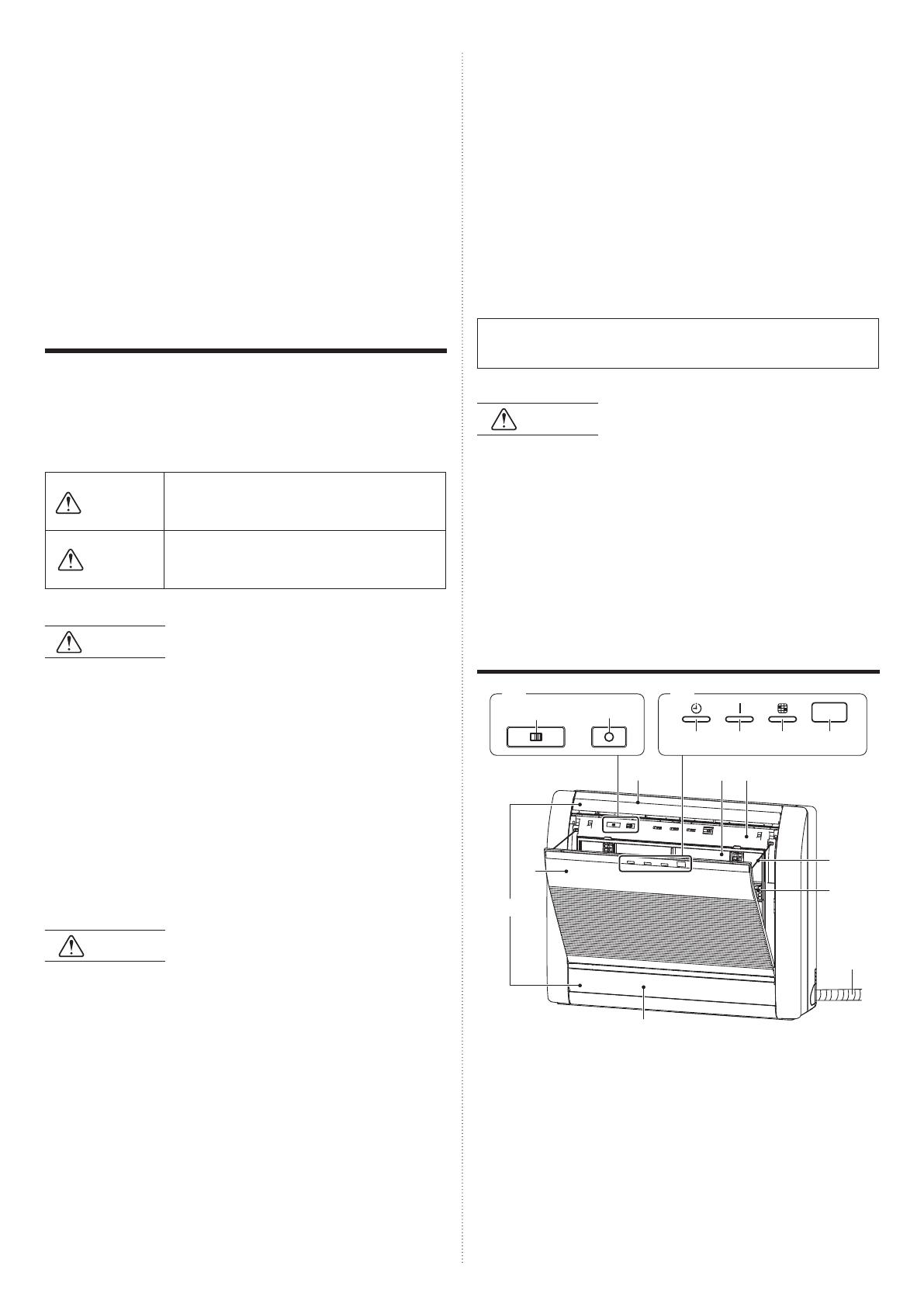
NAME OF PARTS
(5)
(14)
(17)
(13) (11) (10)
(9)
(12)
(6) (7) (8)
(3)
(2)
(1) (4)
(16)
(15)
(1) Operating control panel
(2) Air outlet selection switch
(3) MANUAL AUTO button: This is used to operate the air conditioner
while the remote controller is not available.
(4) Indicator lamps
(5) Timer indicator lamp (orange): It turns on while timer is working.
(6) Operation indicator lamp (green): It turns on while operating.
(7) Filter indicator lamp (red): It turns on when the air fi lter became
dirty. Clean the fi lter referring to “CLEANING AND CARE”. It turns
off when reset by the remote controller after cleaning.
SAFETY PRECAUTIONS
● Before using this product, read these “SAFETY PRECAUTIONS” thor-
oughly and operate in the correct way.
● The instructions in this section all relate to safety; be sure to maintain
safe operating conditions.
● “WARNING” and “CAUTION” have the following meanings in these
instructions:
WARNING
This mark indicates procedures which, if im-
properly performed, might lead to the death or
serious injury of the user.
CAUTION
This mark indicates procedures which, if im-
properly performed, might possibly result in per-
sonal harm to the user, or damage to property.
PRECAUTIONS ON USE
WARNING
● Do not keep exposing oneself to the direct airfl ow of air conditioner for
a long time.
● Do not insert fi ngers or objects into the outlet port or other openings.
● Except for EMERGENCY, never turn off the main or sub breaker of the
indoor units during operation. It will cause compressor failure or water
leakage.
When stopping the operation, stop the indoor unit by operating the con-
trol unit, converter or external input device and then cut the breaker.
Make sure to operate through the control unit, converter, or external
input device.
● If the power supply cord of this product is damaged, it should only be
replaced by the authorized service personal, since special purpose
tools and specifi ed cord are required.
● If any refrigerant happens to leak, extinguish any fl ames, ventilate the
room and get in touch with authorized service personnel.
CAUTION
● Provide occasional ventilation during use.
● Do not use in applications involving the storage of foods, precision
equipment, or art works.
● Do not place animals or plants in the direct path of the airfl ow.
● Do not direct airfl ow at fi replaces or heating apparatus.
● Do not block or cover the inlet port and outlet port.
● Do not climb on, or place objects on, the air conditioner.
● Do not set fl ower vases or water containers on top of air conditioners.
● Do not hang objects from the indoor unit.
● Do not place anything below the indoor unit that should not get wet.
● Always turn off the electrical breaker whenever cleaning the air condi-
tioner or the air fi lter.
Do not pour water or cleaning solvent on the unit directly, or wash the unit with them
.
● Do not expose the air conditioner directly to water.
OPERATION MANUAL
PART No. 9382567064
VRF system indoor unit (Floor type)
CONTENTS
SAFETY PRECAUTIONS ....................................................................... 1
NAME OF PARTS .................................................................................. 1
MANUAL AUTO OPERATION ............................................................... 2
AIRFLOW DIRECTION .......................................................................... 2
AIR OUTLET SELECTION ..................................................................... 2
OPERATING TIPS ................................................................................. 3
CLEANING AND CARE.......................................................................... 3
TROUBLESHOOTING ........................................................................... 5
SPECIFICATIONS .................................................................................. 6
En-2
(8) Remote control signal receiver: This is the place to receive the
signals from the remote controller.
(9) Intake grille
(10) Front panel
(11) Air fi lter
(12) Horizontal louver
(13) Vertical louver (behind the horizontal louver and damper)
(14) Damper
(15) Air cleaning fi lter
(16) Rope
(17) Drain hose
Control unit (optional)
Types of remote controllers:
● Wireless remote controller
● Wired remote controller
● Simple remote controller
For operation method, refer to the operation manual of each control unit.
MANUAL AUTO OPERATION
Use the Manual auto operation in the event the remote control unit is lost
or otherwise unavailable.
CAUTION
Do not press the MANUAL AUTO button with wet hands or pointed ob-
jects, otherwise an electric shock or malfunction may occur.
Starting Operation
Press the MANUAL AUTO button on the operating
control panel.
The operation starts in the setting below.
Operating mode Auto:
When Auto mode cannot be selected, it will
operate in the same mode as the other indoor
unit in the same system. (When no indoor unit is
operating in the same system, the air conditioner
will operate in the Cooling mode.)
Fan speed Auto
Setting temperature 74°F (23°C)
Stopping Operation
Press the MANUAL AUTO button on the operating
control panel.
Emergency Heat
* It is available when this function is enabled. Please consult an autho-
rized service personnel as to whether this function is enabled.
Set Emergency heat
During heating operation, press the MANUAL AUTO
button on the operating control panel.
Auxiliary heater will be primary heater, and the outdoor unit will stop.
The Operation indicator lamp (green) blinks during the Emergency heat
operation.(3 seconds on, 1 second off .)
Cancel Emergency heat
During the Emergency heat operation, press the MAN-
UAL AUTO button on the operating control panel.
AIRFLOW DIRECTION
Up/down airfl ow direction
The up/down airfl ow direction
can be controlled with the remote
controller.
1
2
3
4
Cooling, Dry
and Heating
Left/right airfl ow direction
The left/right airfl ow direction can be manually set by adjusting the verti-
cal louvers.
CAUTION
Always adjust the vertical louvers when the damper is open. Opening the
damper forcibly with hands can cause damper to malfunction.
AIR OUTLET SELECTION
With this function , air come out simultaneously from the upper and lower
air outlets so that the room can be cooled or heated eff ectively. This
function is set using the switch behind the front grille of the Indoor unit.
(This function is available in cooling and heating operation.)
How to set the out air outlet
Upper air outlet only Upper and lower air outlets
Set the air outlet
selection switch to
Set the air outlet
selection switch to
Air blows out automatically from
the upper and lower air outlets as
shown in the table below.
NOTES:
Set the air outlet selection switch to the end. Otherwise, air outlet cannot
be selected as intended.
En-3
Automatic defrosting
● When using the Heating mode under conditions of low outdoor air
temperature high humidity, frost may form on the outdoor unit, result-
ing in reduced operating performance. In order to prevent this kind of
reduced performance, this unit is equipped with Automatic defrosting
function. If frost forms, the air conditioner will temporarily stop, and the
defrosting circuit will operate briefl y (for about 4 to 15 minutes).
During Automatic defrosting operation, the Operation indicator lamp
(green) will blink.
Oil recovery operation
● Periodically, the oil recovery operation is performed in order to return
compressor oil to the outdoor unit.
During oil recovery operation, the Operation indicator lamp (green) will
blink (for about 10 minutes).
Temperature and humidity range
● The temperature and humidity required for operating this product is as
shown in the following table.
Cooling/Dry Mode Heating Mode
Outdoor
temperature
Please refer to the specifi cations of outdoor units.
Indoor
temperature
About 64 to 90 °F DB
(18 to 32 °C DB)
About 50 to 86 °F DB
(10 to 30 °C DB)
Indoor humidity About 80% or less
● If the air conditioner is operated under higher temperature conditions
than those listed, the built-in protection circuit may operate to prevent
internal circuit damage. Also, during Cooling and Dry modes, if the unit
is used under conditions of lower temperature than those listed above,
the heat-exchanger may freeze, leading to water leakage and other
damage.
● If the unit is used for long periods under high-humidity conditions,
condensation may form on the surface of the indoor unit, and drip onto
the fl oor or other objects underneath.
● Do not use this unit for any purposes other than the Cooling, Heating,
Dehumidifying, and air-circulation of rooms in ordinary dwellings.
CLEANING AND CARE
CAUTION
● Before cleaning the unit, be sure to stop the unit and disconnect the
power supply.
● Do not stand on an unstable platform when cleaning.
● When removing and replacing the air fi lters, be sure not to touch the
heat exchanger, as personal injury may result.
● Be sure the intake grille is installed securely.
● Do not clean the inside of the unit by yourself. To clean the inside,
always consult authorized service personnel.
● When cleaning the unit’s body, do not use water hotter than 104°F
(40°C), harsh abrasive cleansers, or volatile agents like benzene or
thinner.
● If dirt is allowed to accumulate on the air fi lter, airfl ow will be reduced,
lowering operating effi ciency and increasing noise.
During periods of normal use, the air fi lters should be cleaned every 2
weeks.
Description of operation
(When set to the upper and lower air outlets)
Cooling mode Dry mode Heating mode
Upper and
lower airfl ow
Upper airfl ow Upper airfl ow
only
Upper and
lower airfl ow
Upper airfl ow
Room temper-
ature and set
temperature
are diff erent.
Room tem-
perature is
close to set
temperature,
or the air con-
ditioner has
operated for 1
hour.
Airfl ow
temperature is
high.
Airfl ow
temperature
is low.
(During
defrosting op-
eration, start
of operation,
etc.)
OPERATING TIPS
Operation and Performance
About priority state and standby state
● Multiple indoor units can be connected within the same system.
Depending on the system, choice of operating mode are limited.
Cooling priority state:
When the other indoor units within the same system operate in cooling
or dry mode, heating cannot be selected at the same time.
Heating priority state:
When the other indoor units within the same system operate in heating
mode, cooling and dry mode cannot be selected at the same time.
Standby state:
The standby state activates when 2 or more indoor units start up at the
same time in diff erent mode. Any indoor unit other than priority mode
will wait in standby state until priority mode changes (operation starts
as soon as priority is switched).
At this time, the Operation indicator lamp (green) will turn on and the
Timer indicator lamp (orange) will blink.
Low ambient cooling
● When the outdoor temperature drops, the outdoor unit’s fans may
switch to Low Speed, or one of the fans may stop intermittently.
Heating performance
● Heating mode operates on the heat pump principle, absorbing heat
from outdoor air and transferring that heat indoors. As a result, the
operating performance is reduced as outdoor air temperature drops.
If you feel that insuffi cient heating performance is being produced, we
recommend you use this air conditioner in conjunction with another
type of heating appliance.
● Heating mode heat your entire room by recirculating air throughout the
room, with the result that some time may be required after fi rst starting
the air conditioner until the room is heated.
En-4
Cleaning the intake grille
1. Remove the intake grille.
(1) Place your fi ngers at both top indicator of the intake grille, and pull
forward; if the intake grille seems to catch part way through its move-
ment, continue pulling down to remove.
(2) Unhook the ropes which holds the intake grille.
(1)
(1)
(2)
(2)
Rope
Intake
grille
2. Clean with water.
Remove dust with a vacuum cleaner; wipe the unit with warm water, then
dry with a clean, soft cloth.
3. Replace the intake grille.
(1) Hook the ropes.
(2) Set the left and right mounting shafts into the bearings at the bottom
of the panel.
(3) Press the place where the mark on the diagram indicates and close
the intake grille.
(1)
(3)
(3)
(2)
(2)
(1)
Intake
grille
Rope
Cleaning the air fi lter
1. Open the intake grille, and remove the air fi lter.
Push down the air fi lter’s handle, disconnect
the 2 upper tabs, and pull out.
2. Remove dust with a vacuum cleaner or by washing.
After washing, allow to dry thoroughly in a shaded place.
3. Replace the air fi lter and close the intake grille.
(1) Align the sides of the air fi lter with the panel, and push in fully, making
sure the 2 upper tabs are returned properly to their holes in the panel.
Panel
Air fi lter
Panel
Air fi lter
(2) Close the intake grille.
● Dust can be cleaned from the air fi lter either with a vacuum cleaner,
or by washing the fi lter in a solution of mild detergent and warm water.
If you wash the fi lter, be sure to allow it to dry thoroughly in a shady
place before reinstalling.
● If dirt is allowed to accumulate on the air fi lter, airfl ow will be reduced,
lowering operating effi ciency and increasing noise.
● During periods of normal use, the Air Filters should be cleaned every
two weeks.
When used for extended periods, the unit may accumulate dirt
inside, reducing its performance. We recommend that the unit be
inspected regularly, in addition to your own cleaning and care. For
more information, consult authorized service personnel.
When shutting down the unit for one month or more, fi rst allow the
fan mode to operate continuously for about one-half day to allow
internal parts to dry thoroughly.
Air cleaning fi lter installation
1. Open the intake grille and remove the air fi lters.
2. Install the air cleaning fi lter set (set of 2).
Set the air cleaning fi lter into the panel.
Catch it on 5 places of picks.
(3 places of upper parts and lower part 2 places.)
Air cleaning fi lter
En-5
3. Install the 2 air fi lters and close the intake grille.
● When air cleaning fi lters are used, the eff ect will increased by setting
the fan speed to “High”.
Replacing the air cleaning fi lter
Replace fi lters with the following components (purchased separately).
● Apple-catechin fi lter: UTR-FC03-2
● Ion deodorization fi lter: UTR-FC03-3
1. Open the intake grille and remove the air fi lters.
2. Replace them by two new air cleaning fi lters.
(1) Remove the old air cleaning fi lters in reverse order of their installation.
(2) Install in the same way as for installation of the air cleaning fi lter set.
3. Install the 2 air fi lters and close the intake grille.
In regard to the air cleaning fi lters
Apple-catechin fi lter (1 sheet)
● The fi lters are disposable fi lters. (They cannot be washed and reused.)
● For storage of the fi lters, use the fi lters as soon as possible after the
package has been opened.
● (The air cleaning eff ect decreases when the fi lters are left in the
opened package)
● Generally, the fi lters should be exchanged about every 3 months.
Please buy dedicated Apple-catechin fi lter (UTR-FC03-2) (Sold sepa-
rately) to exchange the used dirty air cleaning fi lters.
Ion deodorization fi lter (1 sheet) - light blue
● The fi lters should be exchanged about every 3 years so as to maintain
the deodorizing eff ect.
Please buy dedicated Ion deodorization fi lter (UTR-FA13-2) (Sold
separately) when exchanging the fi lters.
Maintenance of ION DEODORIZATION FILTER
In order to maintain the deodorizing eff ect, please clean the fi lter in the
following way every 3 months.
(1) Remove the fi lter.
(2) Clean with water and dry in the air.
1) Flush the fi lters with high-pressure hot water until the surface of
the fi lters are covered with water. Please fl ush with diluent neutral
detergent. (Never wash by reaming or rubbing, otherwise it will
damage the deodorizing eff ect.)
2) Rinse with water fl ow.
3) Dry in shade.
(3) Reinstall the fi lter.
Cleaning body
Wash the body with warm water, and then dry with a clean and soft cloth.
When not using for an extended period
If you have shut down the indoor unit for 1 month or more, perform the
FAN operation for half a day to dry the internal parts thoroughly before
you perform normal operation.
After extended non-use of the unit
Leave the breaker on for at least 12 hours before starting operation when
it is to be used again.
Additional inspection
After long period of use, accumulated dust inside the indoor unit may re-
duce the product performance even if you have maintained the unit with
instructed daily care or cleaning procedures written in this manual.
In such a case, a product inspection is recommended.
For more information, consult authorized service personnel.
TROUBLESHOOTING
The following conditions are not breakdowns or op-
eration failures.
Doesn’t operate immediately:
● If the unit is stopped and then immediately started again, the com-
pressor will not operate for about 3 minutes, in order to prevent fuse
blowouts.
● Whenever the electrical breaker is turned off then on again, the protec-
tion circuit will operate for about 3 minutes, preventing unit operation
during that period.
Airfl ow is weak or stops:
● When Heating operation is started, indoor unit’s fan may temporarily
stop, to allow internal parts to warm up.
● During Heating operation, if the room temperature rises above the
thermostat setting, the outdoor unit will stop, and the indoor unit’s fan
will stop. If you wish to warm the room further, set the thermostat for a
higher setting.
● During oil recovery operation, the airfl ow may stop for approximately
10 minutes. (Refer to “OPERATING TIPS”)
● During Heating operation, the unit will temporarily stop operation (be-
tween 4 and 15 minutes) as the Automatic defrosting mode operates.
(Refer to “OPERATING TIPS”)
● The fan may operate at low speed during Dry operation or when the
unit is monitoring the room’s temperature.
● In the monitoring in the Auto mode, the fan will operate at low speed.
En-6
Indicator lamps are blinking:
● The Operation indicator lamp (green) fl ashes:
An oil recovery operation is being performed. (Refer to “OPERATING
TIPS”)
The Automatic defrosting operation is being performed. (Refer to “OP-
ERATING TIPS”)
● The Operation indicator lamp (green) and Timer indicator lamp (or-
ange) are blinking alternately:
It has recovered from a power outage.
● The Operation indicator lamp (green) and Timer indicator lamp (or-
ange) are blinking simultaneously:
It is operating in the test run mode. Ask a manager as there may be
maintenance being conducted.
● The Operation indicator lamp (green) is on and the Timer indicator
lamp (orange) is blinking:
This is the standby state. (Refer to “OPERATING TIPS”)
Noise is heard:
● In the following conditions there are sounds of water fl owing from the
indoor unit and the operation sound becomes loud. These are the
refrigerant fl ow sound.
When operation starts
When oil recovery operation fi nishes
When Automatic defrosting operation fi nishes
● During operation, a slight squeaking sound may be heard. This is the
result of minute expansion and contraction of the panel due to tem-
perature changes.
● During Heating operation, a sizzling sound may be heard occasionally.
This sound is produced by the Automatic defrosting operation. (Refer
to “OPERATING TIPS”)
Smells:
● Some smell may be emitted from the indoor unit. This smell is the
result of room smells (furniture, tobacco, etc.) which have been taken
into the air conditioner.
Fog comes out of the indoor unit:
● During Cooling operation, a thin mist may be seen emitted from the
indoor unit. This results from the sudden Cooling of room air by the air
emitted from the air conditioner, resulting in condensation and misting
.
Steam comes out of the outdoor unit:
● During Heating operation, the outdoor unit’s fan may stop, and steam
may be seen rising from the unit. This is due to the Automatic defrost-
ing operation. (Refer to “OPERATING TIPS”)
Water is produced from the outdoor unit:
● During Heating operation, water may be produced from the outdoor
unit due to the Automatic defrosting operation.
The following conditions may not be breakdowns so
check again.
Doesn’t operate at all:
● Has there been a power failure?
● Has a fuse blown out, or a circuit breaker been tripped?
● Is the main power switch set to the OFF position?
● Are you trying to engage in an operation diff erent from the priority
state? (Refer to “OPERATING TIPS”)
● Is it in standby state? (Refer to “OPERATING TIPS”)
The operation mode cannot be changed:
● Are you trying to change to an operation diff erent from the priority
conditions? (Refer to “OPERATING TIPS”)
Poor Cooling (or Heating) performance:
● Did you adjust the temperature setting correctly?
● Is the air fi lter dirty? (Refer to “CLEANING AND CARE”)
● Are the air conditioner’s inlet port or outlet port blocked?
● Is there a window or door open?
● In the case of Cooling operation, is a window allowing bright sunlight to
enter? (Close the curtains.)
● In the case of Cooling operation, are there heating apparatus and com-
puters inside the room, or are there too many people in the room?
● Is the fan speed set to low?
Temperature does not fall down well.
● Temperature may not fall down depending on the room conditions.
(While high humidity or the room temperature is high.) (Refer to “OP-
ERATING TIPS”)
Set the temperature lower than the room temperature and use it.
In the following situations, stop operation immediately
and get in touch with authorized service personnel.
● The problem cannot be solved even when the troubleshooting checks
have been performed.
● The Filter indicator lamp (red) is blinking very fast.
● The wired remote controller or simple remote controller indicate "Er"
(when connected).
● It has burning smell.
SPECIFICATIONS
MODEL
AGUA
4TLAV2
AGUA
7TLAV2
AGUA
9TLAV2
AGUA
12TLAV2
AGUA
14TLAV2
POWER SOURCE 208/230 V ~ 60 Hz
AVAILABLE
VOLTAGE RANGE
187 to 253 V
COOLING
CAPACITY
Btu/h
(kW)
4,000
(1.2)
7,500
(2.2)
9,500
(2.8)
12,000
(3.5)
14,000
(4.1)
HEATING
CAPACITY
Btu/h
(kW)
4,400
(1.3)
9,500
(2.8)
10,900
(3.2)
13,500
(4.0)
15,600
(4.6)
SOUND PRESSURE LEVEL
HIGH
dB [A]
35/36
(*1)
37 38 42 46
MED - HIGH
dB [A]
33 35 36 39 42
MED
dB [A]
31 33 34 37 39
MED - LOW
dB [A]
30 31 31 35 36
LOW
dB [A]
28 29 29 33 33
QUIET
dB [A]
22 22 22 30 30
DIMENSIONS & WEIGHT
HEIGHT
[in (mm)]
23-5/8 (600)
WIDTH
[in (mm)]
29-1/8 (740)
DEPTH
[in (mm)]
7-7/8 (200)
WEIGHT
[lbs (kg)]
33 (15)
*1: This value is “cooling operation/heating operation”.
Acoustic Noise Information:
The maximum sound pressure level is less than 70 dB (A) for both
indoor unit and outdoor unit. According IEC 704-1 and ISO 3744.
  • Page 1 1
  • Page 2 2
  • Page 3 3
  • Page 4 4
  • Page 5 5
  • Page 6 6
  • Page 7 7
  • Page 8 8

Fujitsu AGUA4TLAV2 Operating instructions

Type
Operating instructions
This manual is also suitable for

Ask a question and I''ll find the answer in the document

Finding information in a document is now easier with AI