Page is loading ...

Note: Installation should be in accordance with accepted
plumbing practices. Flush all piping thoroughly before
installation.
TO INSTALL
1. Position mixer 1-15/16″ ± 1/2″ [49mm ± 13mm] from inlet
center to finished wall surface. The tub outlet port is
marked “TUB” and should face down. Facing front of
mixer, connect hot water to left side and connect cold
water to right side. The valve has “C” and “H” cast into
the body near the appropriate inlet ports.
2. For standard inlets: Valve is factory-set for standard
inlets (“TOP” stamped on stem should face shower outlet
“S”, see Figure 3.) If reversed inlets are required due to
back-to-back installation (Cold water supply on the left
and Hot water supply on the right), see Figure 3 and fol-
low instructions a– d below:
a. Connect cold inlet to hot port (“H”) and hot inlet to
cold port (“C”). Note: Do not turn valve upside down.
If valve is upside down, water will not flow properly
through tub spout or showerhead.
b. Turn water off with checkstops, remove high temp.
limit stop and bonnet.
c. Rotate stem 180°, and reinstall bonnet and high temp.
limit stop.
Note: Be certain the word “TOP” stamped on stem is
facing toward tub outlet “T”.
d. Hot and Cold inlets should be re-identified for
reversed inlets to avoid confusion during future main-
tenance.
3. For tub and shower installations, see Figure 1. Pipe bot-
tom outlet port “T” directly to the diverter tub spout. The
Biltmore mixer body is designed to operate without the
use of a twin ell. Pipe top outlet port “S” to the shower-
head.
Be certain that the bottom outlet port “TUB” is piped to
the tub spout; if outlet connections are reversed, the
mixer will not function properly.
4. For shower only installation, see Figure 2. Pipe top outlet
port “S” directly to the showerhead and plug bottom port.
5. Rough-in guide installation…
a. When piping installation is completed and before
doing the finished wall, slide rough-in guide onto the
mixer stem and press fit into place. (See Figure 5.)
b. The rough-in guide will insure the proper size opening
for mixer and checkstop shut-off and repair accessi-
bility, as well as protect the chrome-plated sleeve from
damage during drywall and tile installation.
6. To install dial gaskets, peel backing off gaskets and
attach gaskets to inside of dial plate.
7. After wall is completed, remove rough-in guide and
attach dial assembly and handle to mixer body with the
screws furnished. See Figure 4.
CAUTION: When soldering during installation process, do
not heat the valve any higher than the temperature required
to flow solder. Excessive overheating of the valve may cause
damage to the balancing cartridge mechanism. By following
this recommendation, you will be able to solder the valve
without removing either the cartridge or the checkstop
internals. If either brazing or resistance (electric) solder is to
be used, all valve internals must be removed.
8. Maximum temperature setting must be set at the job
site. High temperature limit stop is located on the bon-
net. Remove O-ring and discard. Slide the retainer and
the high temperature limit stop out. Rotate stem to
desired maximum temperature, but no greater than
115°F (46°C). Slide back the maximum temperature limit
stop touching the tab on the stem. Slide the retainer
back all the way to secure the high temperature limit
stop. Install handle.
The maximum temperature setting must be re-adjusted
if the hot water supply temperature is changed, and
also seasonally to compensate for changes in the
cold water supply temperature.
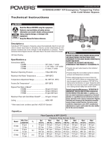
INSTALLATION INSTRUCTIONS
BILTMORE SERIES 900
Pressure Balancing Valves
5-3/8" [137]
12" [305]
4" [101]
APPROX.
A
1-7/16" [37] MIN.
2-7/16" [62] MAX.
WALL
1/2" [13]
TUB RIM
1/2-14" NPT
MALE INLET
ALL DOTTED LINE PIPING SUPPLIED BY OTHERS.
1/2" COPPER
SLIP JOINT
CONNECTION
3-1/4" [82]
5" [127]
4-5/8" [118] DIA
ROUGH-IN
GUIDE
1/2" IPS CONNECTIONS
OR
1/2" COPPER SWEAT
CONNECTIONS
NOTE:
'T' TO BE
ON BOTTOM
AS SHOWN
78" [1981 ]
APPROX.
TO FINISHED
FLOOR
Figure 1: Rough-in Dimensions — Tub and Shower
TUB OUTLET
TUB OUTLET
TO BE PLUGGED.
TO BE PLUGGED.
PLUG BY OTHERS.
PLUG BY OTHERS.
5" [127]
5" [127]
A
24" [609]
24" [609]
APPROX.
APPROX.
WALL
WALL
1-7/16" [37] MIN.
1-7/16" [37] MIN.
2-7/16" [62] MAX.
2-7/16" [62] MAX.
1/2" [13]
1/2" [13]
1/2" IPS CONNECTIONS
1/2" IPS CONNECTIONS
OR
OR
1/2" COPPER SWEAT
1/2" COPPER SWEAT
CONNECTIONS
CONNECTIONS
1/2-14" NPT
1/2-14" NPT
MALE INLET
MALE INLET
ALL DOTTED LINE PIPING SUPPLIED BY OTHERS.
ALL DOTTED LINE PIPING SUPPLIED BY OTHERS.
78" [1981]
78" [1981]
APPROX.
APPROX.
TO FINISHED
TO FINISHED
FLOOR
FLOOR
4-5/8" [118] DIA
4-5/8" [118] DIA
ROUGH-IN
ROUGH-IN
GUIDE
GUIDE
NOTE:
NOTE:
'T' TO BE
'T' TO BE
ON BOTTOM
ON BOTTOM
AS SHOWN
AS SHOWN
3-1/4" [82]
3-1/4" [82]
Figure 2: Rough-in Dimensions — Shower only
Dimensions in inches [millimeters]
II900

II900 Page 2
HOTHOT
PORTPORT
COLDCOLD
PORTPORT
SHOWER OUTLETSHOWER OUTLET
TUB OUTLETTUB OUTLET
FOR STANDARD INLETSFOR STANDARD INLETS
COLD WATERCOLD WATER
INTOINTO
COLD PORT:COLD PORT:
1. "TOP" STAMPED ON STEM1. "TOP" STAMPED ON STEM
FACES SHOWER OUTLET. FACES SHOWER OUTLET.
2. FLATS ON STEM MUST FACE2. FLATS ON STEM MUST FACE
TOP AND BOTTOM OUTLETS. TOP AND BOTTOM OUTLETS.
FOR REVERSED INLETSFOR REVERSED INLETS
COLD WATERCOLD WATER
INTOINTO
HOT PORT:HOT PORT:
1. "TOP" STAMPED ON STEM1. "TOP" STAMPED ON STEM
FACES TUB OUTLET FACES TUB OUTLET.
2. FLATS ON STEM MUST FACE2. FLATS ON STEM MUST FACE
TOP AND BOTTOM OUTLETS. TOP AND BOTTOM OUTLETS.
Figure 3: Stem Position Information
POWERS
POWERS
Dial Gaskets
Dial Gaskets
ABS
ABS
Dial
Dial
Plate*
Plate*
Dial Plate
Dial Plate
Screws (2)
Screws (2)
ABS Lever Handle
ABS Lever Handle
Kit #900-103
Kit #900-103
Metal Lever
Metal Lever
Handle*
Handle*
900-029
900-029
ABS Lever
ABS Lever
Handle Screw
Handle Screw
800-164
800-164
ABS Lever
ABS Lever
Handle Button
Handle Button
900-096
900-096
ABS Lever
ABS Lever
Handle
Handle
900-091
900-091
Acrylic
Acrylic
Handle*
Handle*
900-019C
900-019C
Acrylic
Acrylic
Handle
Handle
Button
Button
900-140
900-140
Acrylic
Acrylic
Handle Screw
Handle Screw
800-168
800-168
Metal Lever
Metal Lever
Handle Screw
Handle Screw
800-164
800-164
900-094
900-094
080-026
080-026
900-093
900-093
(
not used in 905 valves)
not used in 905 valves)
900-090
900-090
*Round Stainless Steel Dial Plate
*Round Stainless Steel Dial Plate
900-020A
900-020A
Graphic
Graphic
Insert
Insert
900-095
900-095
Sleeve*
Sleeve*
900-132
900-132
Figure 4
Silicone
Grease
Note: For valves sold without checkstops, it is recom-
mended that the valve be installed where there is
shut-off upstream of the valve, so that the valve
may be easily serviced and accessed. If this is not
possible, the valve should include a shutoff or com-
bination checkstop/shutoff on the inlets.
Figure 6: Max. Temperature Setting/Handle Rotation Stop
REPAIR KITS
For further information on repair and maintenance, see TI900.
Note: SWEAT inlets shown. THREADED inlets also available.
* Use Sleeve 900 132 in Kit 900 268 with ABS Dial.
Use Sleeve 800015H in Kit 900 269 with Round
Stainless Dial.
Figure 5
II900 0632 EDP# 6512223
TROUBLESHOOTING
Description Troubleshooting Repair Kit No.
Gasket and Disc • Water leaks at valve stem and/or bonnet. 900 030 Models 1 and 2
Replacement • Water leaks at valve shutoff.
• Water leaks at checkstop. 900 028 Model 3
Internals • With mixer handle in MID position, HW flows with CW. 900031A, Model 1
Replacement checkstop closed or CW flows with HW checkstop closed. 900 031 Model 2
900 032 Model 3
Checkstop • Checkstop will not completely shut off. 900 049 Models 1 and 2
Replacement 900 050 Model 3
High Temperature Stop
Retainer
O-ring
© 2006 Powers
USA: Phone: 1.800.669.5430 • Fax 1.847. 229. 0526 • www.powerscontrols.com
Canada: Phone: 1.888.208.8927 • Fax 1.888. 882.1979 • www.powerscontrols.ca
/