Page is loading ...

P/N 30-3352
Water/Methanol Injection Kit V2
Multi-Input Controller - Ext. MAP/MAF/IDC
NO TANK INCLUDED
AEM Performance Electronics
AEM Performance Electronics, 2205 126th Street Unit A, Hawthorne, CA 90250
Phone: (310) 484-2322 Fax: (310) 484-0152
http://www.aemelectronics.com
Instruction Part Number: 10-3352
Document Build 5/14/2020
Instruction
Manual
WARNING!
Improper installation and/or adjustment of this product can result in major engine/vehicle damage. For
technical assistance visit our dealer locator to find a professional installer/tuner near you.
Note: AEM holds no responsibility for any engine damage or personal injury that results from the
misuse of this product, including but not limited to injury or death caused by the mishandling of
methanol.
STOP!
THIS PRODUCT HAS LEGAL RESTRICTIONS.
READ THIS BEFORE INSTALLING/USING!
THIS PRODUCT MAY BE USED SOLELY ON VEHICLES USED IN SANCTIONED COMPETITION WHICH MAY NEVER BE USED
UPON A PUBLIC ROAD OR HIGHWAY, UNLESS PERMITTED BY SPECIFIC REGULATORY EXEMPTION. (VISIT THE “EMISSIONS”
PAGE AT HTTP://WWW.SEMASAN.COM/EMISSIONS FOR STATE BY STATE DETAILS.)
IT IS THE RESPONSIBILITY OF THE INSTALLER AND/OR USER OF THIS PRODUCT TO ENSURE THAT IT IS USED IN
COMPLIANCE WITH ALL APPLICABLE LAWS AND REGULATIONS. IF THIS PRODUCT WAS PURCHASED IN ERROR, DO NOT
INSTALL AND/OR USE IT. THE PURCHASER MUST ARRANGE TO RETURN THE PRODUCT FOR A FULL REFUND.
THIS POLICY ONLY APPLIES TO INSTALLERS AND/OR USERS WHO ARE LOCATED IN THE UNITED STATES; HOWEVER
CUSTOMERS WHO RESIDE IN OTHER COUNTRIES SHOULD ACT IN ACCORDANCE WITH THEIR LOCAL LAWS AND
REGULATIONS.

Water/Methanol Injection V22
© 2020 AEM Performance Electronics
IMPORTANT SAFETY NOTICE REGARDING
METHANOL
AEM strongly recommends that users never exceed a 50% methanol concentration
when using any AEM Water/Methanol system or component.
All AEM water/methanol injection systems and components (pump, lines, fittings, filter, flow
sensor, tank, and nozzles) are 100% chemically compatible with methanol. However, for
safety reasons we strongly recommend that users never use more than a 50% methanol
concentration in our systems.
Methanol is a toxic and highly flammable chemical. 100% methanol ignites easily and burns
vigorously with an almost undetectable flame. Methanol can be absorbed through the skin,
and even small amounts can cause blindness or even death. Using this fluid at high
pressures, without dilution, in an under-hood environment with nylon lines and push-to-
connect fittings is very unsafe. The performance advantages of using greater than 50%
methanol concentrations are small, if they exist at all. However, the safety issues are very
real and far outweigh any perceived benefit of running high concentrations of methanol.
Note: AEM holds no responsibility for any engine damage or personal injury that
results from the misuse of this product, including but not limited to injury or death
caused by the mishandling of methanol.

Water/Methanol Injection V2
3
© 2020 AEM Performance Electronics
INTRODUCTION
Congratulations on your purchase of the AEM Water/Methanol Injection V2 Kit. This document will help guide
you through the setup and installation process. Please take the time to review its contents prior to installation.
Pay especially close attention to any bolded text, as it indicates an important note or step in the process.
Before beginning installation of electronic components, please disconnect the ground side of your battery. This
is for your safety.
SPECIFICATIONS
200 PSI injection pump
Progressive pump controller with “Boost Safe” feature
High amperage pump driver with over-current, over-voltage and under-voltage protection
Error protection output with over-current, over-voltage and over-temperature protection
Two system status LED indicators; shows pump duty cycle and system errors
Pump open and short detection and indication; works even if the pump is off
Test button that manually triggers pump
Two dial pump speed control

Water/Methanol Injection V24
© 2020 AEM Performance Electronics
30-3352 Contents
Parts List:
Hardware Kit:
Quantity
Description
Part #
Quantity
Description
Part #
20 ft
High Pressure ¼” Nylon Hose
35-4500-20
36 in
3/8" High Temp Wire Wrap
8-169
1
200 PSI Pump With Integral Fittings
5843-2S0D-
B744AM
6 in
Edge Protector
8-111-E
1
1/8” Tee Fitting
35-2147
1
Progressive Injection Module
35-4551
10
6” Zip Tie
8-113-E
4
Bolt, Hex Head,
5/16-18 x 1.25”
1-2115
1
12 ft Wiring Harness
35-3451
4
Bolt, Hex Head,
8-32 x 1.5”
1-2116
8
Screw, Pan Head,
#8 x 1.0"
1-3048
4
Screw, Pan Head,
#6 x 0.5"
1-3049
Injector Nozzle Kit:
4
Nut, Nylock, 5/16-18
1-3055
Quantity
Description
Part #
4
Nut, Nylock, 8-32
1-2537
1
Atomizing Pintle, Small (250 cc/min)
35-4554-1
12
Washer, #8 x 3/4"
1-3051
1
Atomizing Pintle, Medium (500
cc/min)
35-4554-2
4
Washer, #8 x 7/16"
1-3050
1
Atomizing Pintle, Large (1000 cc/min)
35-4554-3
4
Washer, 5/16
1-3031-E
1
Nozzle Filter
35-4556
4
Washer, Fender, 5/16
1-3054
1
Nozzle Body
35-4557
1
5mm Cockpit LED
35-4505
1
Fitting, 1/4 Tube, Cliptype
35-4561
2
Butt Connector,
14-16 AWG (blue)
8-360
1
Spring
35-4562
9
Butt Connector,
18-22 AWG (red)
8-361
1
Check Valve
35-4563
4
Ring Terminal,
14-16 AWD (blue)
8-354
1
Check Valve Seal
35-4570
1
Retaining Clip
35-4565

Water/Methanol Injection V2
5
© 2020 AEM Performance Electronics
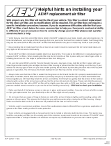
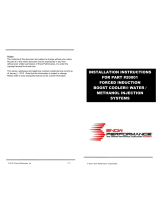
INSTALLATION
Diagram
*Viewed from Wire Side of Connector
NOTE: THIS KIT INCLUDES NEW STYLE INJECTOR NOZZLES THAT HAVE INTERNAL CHECK VALVES.
AN EXTERNAL CHECK IS NO LONGER NEEDED OR INCLUDED IN THIS KIT.

Water/Methanol Injection V26
© 2020 AEM Performance Electronics
Installation Checklist
The following list of steps is an overview of the installation process. A complete and more detailed list of each
step including optional peripherals is defined later in this document.
Install Pump
o Select suitable location for pump near and below the lowest fluid level of tank.
o Fasten with 4 of the #8 sheet metal screws along with the 4 small washers or the #8-32 bolts
and Nylock nuts.
o Cut supplied nylon hose with a sharp razor blade and install from tank to pump.
Install Controller
o Disconnect ground side of battery during electronic installation.
o Find suitable location for controller inside driver’s compartment.
o Find location in driver’s field of view and install external LED.
o Follow the wire diagram and connect wires from supplied wire harness.
o Connect the blue wire to external input signal.
Flush Tank
o Connect the remainder of hose to pump. (DO NOT CONNECT NOZZLE.)
o Fill tank with water. (AEM recommends using distilled water.)
o Turn on key power to power on controller.
o Use TEST button on controller to flush the tank into a separate container.
o Drain tank and proceed to next step.
Connect Nozzle to System
o Select nozzle and connect to nylon hose.
o Fill tank with water.
o Use TEST button on controller to test complete system.
System Check
o While pushing the TEST button ensure that no errors are reported and that the system is
producing a gradually increasing flow out of the nozzle.
o This may require pressing the TEST button multiple times to purge the system.
o Drain tank and fill with desired water/methanol mixture.
o DO NOT use a hydrocarbon fuel. Water and methanol are the only supported fluids.
Install Nozzle
o The nozzle must be mounted such that it is above the tank. Failure to do so may
lead to fluid leaking into the intake tract due to gravity or siphoning, which may
result in engine damage.
o Find a suitable location to install nozzle. Nozzle must be mounted before the throttle plate.
Nozzle should also be mounted after the MAF sensor if present. Nozzle must also be mounted
after any intercoolers.
o Install nozzle, following instructions for modifying intake to accept the nozzle.
o Cut and install nylon hose from pump to nozzle. Ensure that the hose is not resting, near, or
running on any moving or “hot” parts.
Tune Engine
o Engine tuning is usually required in order to maximize potential power gain.

Water/Methanol Injection V2
7
© 2020 AEM Performance Electronics
Pump Install
Find a suitable location to mount the pump. The
tank and pump must be mounted in the same
area. Pump may be mounted on exterior of
vehicle but should be mounted away from
wheel wells or other areas where it will come
into direct contact with water or road debris.
Pump failures that have clearly been caused
by exposure to water/mud/debris will not be
covered under warranty. This includes, but is
not limited to, the bed of a truck and the inside of
the fender wells. Find a location where the pump
will remain dry.
The pump must be located in the same area as
the tank and should be mounted at or below the
lowest fluid level height. Take note of the
direction of flow, indicated by the arrows on the
pump body, when mounting the pump.
Use four #8 sheet metal screws along with the 4 small washers or the #8-32 bolts and nylock nuts to mount the
pump. The pump can be mounted in any position horizontally or vertically. Once the tank and pump are
mounted, cut the appropriate length of tubing needed to connect the outlet fitting on the tank to the inlet fitting
on the pump. Make sure there are no sharp bends in the tubing. Cut the tubing to length with a clean
perpendicular slice using a sharp razor blade, making sure the ends are clean and square. Push in the hose at
the tank and pump to install. Make sure they are pushed in all the way and check with a light tug on the hose.
Secure the hose to the chassis using sections of the supplied hose routing strip or with zip-ties.
Controller Install
The progressive controller is NOT waterproof and should NOT be mounted in the engine bay! Find a convenient
location for the controller inside the driver’s compartment. The adjustment knobs should remain in an accessible
location but still remain protected from possible water incursion. If you need to extend the wires to mount the
controller use at least 16 AWG wire for the pump and controller ground circuits and 18 AWG for the remainder.
The controller contains an externally accessible fuse; no additional fuses are required. Use the supplied zip-ties
to mount the controller.
Progressive Controller Installation
Pin #
Description
Wire**
Color
Connection
1
Pump Ground
16 AWG
Orange
Connect to ground (black) wire of pump.
2
LED -
20 AWG
Gray
Connect to ground (black) wire of external LED.
3
LED +
20 AWG
Violet
Connect to positive (red) wire of external LED.
4
Solenoid -
20 AWG
Brown/White
1.5A Low Side output. Connect to optional flow control
solenoid.
5
Boost Safe LS
Out
18 AWG
Green
1.7A Low Side output, grounded when error condition
exists.
6
Pump Power
16 AWG
Pink
Connect to the positive (red) wire of pump.

Water/Methanol Injection V28
© 2020 AEM Performance Electronics
Pin #
Description
Wire**
Color
Connection
7
Ground
16 AWG
Black
Main ground connection. Connect directly to battery
ground.
8
Level Switch+
20 AWG
White
Connect to the white wire of the fluid tank level sensor*
9
Level Switch-
20 AWG
Brown
Connect to the black wire of the fluid tank level sensor*
10
Arm Switch +
20 AWG
Yellow
Arms injection system. Connect to a switched 12V
source.
11
External Signal
18 AWG
Blue
Connect to External Signal (0–5V, injector duty, MAF
frequency).
12
Power 12V
16 AWG
Red
Main Power Connection. Connect directly to positive
battery terminal.
*Note: If fluid tank is equipped with previous generation level sensor, identified by having two black wires, then pins 8 (white)
and 9 (brown) may be connected to either of the two black sensor wires. The polarity is unimportant.
**Note: If you need to extend the wires to mount the controller use at least 16 AWG wire for the pump and controller ground
circuits and 18 AWG for the remainder.
External LED Install
Find a suitable location in the driver’s line of sight to mount the external LED. Mount the LED and run the wires
to the controller. The LED indicates the operation of the controller. If the pump is off and there are no errors, the
LED will be off. If there are no errors and the pump is on, the LED intensity will vary with the pump speed. If
there are any errors, they will be indicated by flashing the LED.
External MAP, Injector Duty, MAF Overview
The connection of the External MAP/MAF pin will depend on the desired mode of operation. Please follow the
table in determining where to connect this wire.
Mode of operation
Dip Switch
Settings
Pin Installation location
MAF / MAP (0V–5V)
ON – ON – ON
*Connect to signal output from MAF/MAP where signal
range is 0V–5V.
Injector Duty (0%–100%)
OFF – OFF – ON
*Connect to the injector duty signal that is active low. Multi-
Pulse Injection, as is found on some diesel applications, is
NOT supported. Please verify a single pulse for each
injection event with an oscilloscope prior to operation.
Frequency MAF
(40Hz–220Hz)
OFF – ON – OFF
*Connect to the frequency MAF signal.
Frequency MAF
(400Hz–2200Hz)
OFF – ON – ON
*Connect to the frequency MAF signal.
Frequency MAF
(2kHz–14kHz)
ON – OFF – OFF
*Connect to the frequency MAF signal.

Water/Methanol Injection V2
9
© 2020 AEM Performance Electronics
*Please consult the factory service manual to find the appropriate wire to tap for the above connections. It is acceptable to make
this tap close to the sensor/injector or nearer to the ECU itself, whichever is more convenient.

Water/Methanol Injection V210
© 2020 AEM Performance Electronics
External MAP 0–5V Installation
Operation:
The 0–5 Volt external MAP mode is designed for vehicles running high boost, beyond that of the Internal and
HD models, or for users who already have a sensor or output of their MAP with a range of 0–5 Volts. See Table
1 for compatible AEM MAP sensors.
Dip Switch Settings:
ON – ON – ON
Setup, Connection:
To set up your system for external MAP you must first find the correct source to connect to. In order to locate
the correct signal the use of a voltmeter is required. Once you have located your MAP sensor, check the wires
to find the “signal” wire. The signal wire should remain at or near 0 Volts when the car is turned off or is not
running. Once the vehicle is started, it should continue to remain at or near 0, though it may begin oscillate up
and down slightly. To determine if you do in fact have the correct wire, rev the engine while monitoring the
voltage. You should observe the signal rising and falling with engine speed. Please note that you may need to
rev the engine high enough to put it into boost. Once you have found the correct signal wire, you may tap onto it
(if it is used by other devices), or connect it directly to the Water/Methanol Controller (Pin #11 – Blue).
Testing:
To test your setup it is recommended you finish the installation, but before installing the nozzle run the engine
and ensure the system is operating as expected. That is, when the engine is running and the MAP sensor is
outputting in a range set by the controller you will get flow. You want to ensure you are not getting flow when the
engine is turned off or it is not expected. This could be due to improper wiring or having the incorrect mode
selected.
Pressure Range
AEM Brass Sensor Kit
P/N
AEM Stainless Steel
Sensor Kit P/N
1 Bar / 15PSIa
30-2131-15G
30-2130-15
2 Bar / 30 PSIa
30-2131-30
30-2130-30
3.5 Bar / 50 PSIa
30-2131-50
30-2130-50
5 Bar / 75 PSIa
30-2131-75
30-2130-75
100 PSIg
30-2131-100
30-2130-100
Table 1 – Compatible AEM Pressure Sensor Kits

Water/Methanol Injection V2
11
© 2020 AEM Performance Electronics
Injector Duty Installation
Operation:
The Injector Duty mode is designed for vehicles where water/methanol injection rate is desired to be highly
coupled to the injector duty, meaning the more fuel the more water/methanol. This mode can be used when
MAF is not available, or in NA vehicles. Injector duty is NOT intended to work with diesel or other multi-pulse
injection systems.
Dip Switch Settings:
OFF – OFF – ON
Setup, Connection:
To set up your system for injector duty you must first find the correct signal wire to connect to. You must locate
and tap on to one of the two wires going to the fuel injector. One of the wires will be switched +12V (typically
red) and the other will be the desired signal wire from the ECU. Using a voltmeter you can determine if you have
the correct wire by watching the voltage as the engine is running. As duty cycle increases and more fuel
injected, the measured DC voltage will appear lower as viewed on a voltmeter. If you have an oscilloscope or a
way to measure duty cycle, this is even better. Once you are sure you have the correct signal you can tap onto
the signal and connect that to pin #11 (blue wire) on the controller.
Testing:
To test your setup it is recommended you finish the installation, but before installing the nozzle run the engine
and ensure the system is operating as expected. That is, you want to ensure you are not getting flow when the
engine is turned off or it is not expected. This could be due to improper wiring or having the incorrect mode
selected.

Water/Methanol Injection V212
© 2020 AEM Performance Electronics
0–5V MAF Installation
Operation:
The 0–5 Volt MAF mode is designed for vehicles where MAF is used and the output of their MAF sensor is 0–
5V and not a frequency.
Dip Switch Settings:
Mode
DIP Switches
Common Applications
0–5 Volt
ON – ON – ON
VW/Audi 1.8T
Subaru WRX/STi
Nissan S13/S14/S15/300ZX
Setup, Connection:
To set up your system for MAF you must first find the correct source to connect to. In order to locate the correct
signal the use of a voltmeter is required. Once you have located your MAF sensor, check the wires to find the
“signal” wire. The signal wire should remain at or near 0 Volts when the car is turned off or is not running. Once
the vehicle is started, it should continue to remain at or near 0, though it may begin oscillate up and down
slightly. To determine if you do in fact have the correct wire, rev the engine while monitoring the voltage. If the
signal rises and falls with the engine speed, then you have likely identified the correct wire. If you are
experiencing difficulty locating the signal wire, refer to the vehicle’s service manual to locate the MAF signal
wire, and then try to verify again with a voltmeter. Once you have found the correct signal wire, you may tap
onto and connect it to pin #11 (blue) of the Water/Methanol Controller.
Testing:
To test your setup it is recommended you finish the installation, but before installing the nozzle run the engine
and ensure the system is operating as expected. That is, when the engine is running and the MAF sensor is
outputting in a range set by the controller you will get flow. You want to ensure you are not getting flow when the
engine is turned off or when it is not expected. This could be due to improper wiring or having the incorrect
mode selected.

Water/Methanol Injection V2
13
© 2020 AEM Performance Electronics
Frequency MAF Installation
Operation:
The Frequency MAF mode is designed for vehicles where MAF is used and the output of their MAF sensor is
digital and a frequency.
Dip Switch Settings:
Mode
DIP Switches
Common Applications
Frequency MAF
(40Hz–220Hz)
OFF – ON – OFF
1993 and older GM
Frequency MAF
(400Hz–2200Hz)
OFF – ON – ON
1990–1999 Mitsu
1G/2G DSM
Frequency MAF
(2kHz–14kHz)
ON – OFF – OFF
1994+ GM
VW 2.0T, etc.
Setup, Connection:
To set up your system for MAF you must first find the correct source to connect to. In order to locate the correct
signal, the use of a voltmeter is required. Once you have located your MAF sensor, you can begin to check the
wires for the “signal” wire. The signal wire should remain at or near 0 Volts when the car is turned off or is not
running. Once the vehicle is started, it should remain at or near 2.5 Volts. This is because the signal has a duty
cycle of 50% and a voltage range of 0–5V, so the average voltage will be near the middle of this range. To
determine if you do in fact have the correct wire, rev the engine while monitoring the voltage. It should remain
the same regardless of the engine speed. If you are experiencing difficulty locating the signal wire, refer to the
vehicle's service manual to locate the MAF signal wire, and then try to verify again with a voltmeter. Once you
have found the correct signal wire, you may tap onto it and connect it to pin #11 (blue) of the Water/Methanol
Controller.
Testing:
To test your setup it is recommended you finish the installation, but before installing the nozzle run the engine
and ensure the system is operating as expected. That is, when the engine is running and the MAF sensor is
outputting in a range set by the controller you will get flow. You want to ensure you are not getting flow when the
engine is turned off or when it is not expected. This could be due to improper wiring or having the incorrect
mode selected.

Water/Methanol Injection V214
© 2020 AEM Performance Electronics
Pump/Tank Flush
After all wires are hooked up, add water to the tank and, with the hose pointed into a container, press and hold
the TEST push button on the controller module. The TEST button can be used to test the system. The pump
speed will gradually increase from zero to full speed within 3 seconds and then remain full for another 3
seconds before stopping. Repeat the TEST button procedure until you are sure the system is free of any debris
that may have been in the lines or tank. Drain the water out of the tank and refer to the next section on installing
the nozzle.
Nozzle Selection
This injection kit includes three differently sized atomizing pintles that cover a very large range of horsepower
levels. Use the following chart to select the appropriate pintle for your power level. The kit comes with the 500cc
pintle already preassembled.
HP
Fuel Flow
N/A
(.5 BSFC)
Fuel Flow
F/I
(.7 BSFC)
W/M Flow
N/A
W/M Flow
5–10psi
Boost
W/M Flow
10–25psi
Boost
W/M Flow
25+psi
Boost
150
788
1101
95
220
275
330
200
1050
1469
126
294
367
441
250
1313
1836
158
367
459
551
300
1575
2203
189
441
551
661
350
1838
2570
221
514
642
771
Nozzle
400
2100
2937
252
587
734
881
250
450
2363
3304
284
661
826
991
500
500
2625
3671
315
734
918
1101
1000
550
2888
4038
347
808
1010
1212
1000 + 500
600
3150
4406
378
881
1101
1322
1000 + 1000
650
3413
4773
410
955
1193
1432
700
3675
5140
441
1028
1285
1542
750
3938
5507
473
1101
1377
1652
800
4200
5874
504
1175
1469
1762
850
4463
6241
536
1248
1560
1872
900
4725
6608
567
1322
1652
1983
950
4988
6976
599
1395
1744
2093
1000
5250
7343
630
1469
1836
2203

Water/Methanol Injection V2
15
© 2020 AEM Performance Electronics
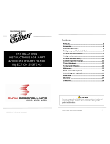
Nozzle Assembly
The nozzles are serviceable and can be disassembled for cleaning. If you find excessive debris in the screen,
check your tank for contamination.
Assembly Instructions:
1. Select your atomizing pintle of choice using the nozzle selection table. Once you have decided on the size of
the pintle for your application, use the table below to help you identify the correct pintle.
Pintle Size
250cc
500cc
1000cc
Picture (Pintle Head)
Picture (Pintle Stem)
Slot
Cupped End
Flat

Water/Methanol Injection V216
© 2020 AEM Performance Electronics
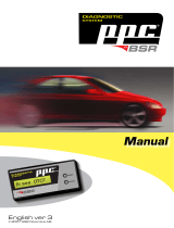
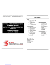
2. The diagram below shows the assembly/disassembly process.
IMPORTANT: Inspect the check valve and check valve seal for any damage before reassembly. Damaged
internals may cause the nozzle to leak, which could result in catastrophic engine damage.
3. In case the check valve comes apart during disassembly, the diagram below shows how the check valve
snaps together. No adhesive is required. The actual EPDM valve will not come out of the valve body.

Water/Methanol Injection V2
17
© 2020 AEM Performance Electronics
Nozzle Mounting
Select the location where the nozzle will be installed. Nozzle must be mounted such that it is higher than
the tank. Failure to do so may lead to fluid leaking into the intake tract due to gravity or siphoning,
which may result in engine damage. Nozzle must be mounted before the throttle plate. Nozzle should also
be mounted after the MAF sensor, if present. Nozzle must also be mounted after any intercoolers. In most
instances, mounting the nozzle 6–8” ahead of the throttle body provides an excellent combination of air charge
cooling and combustion control.
In most instances, the air charge piping can be drilled and tapped for 1/8” NPT to directly mount the nozzle. If
using thin walled tubing it’s suggested that a bung be welded to the piping. Mounting hole should be tapped
deep enough to allow the end of the nozzle to be nearly flush with the interior of the intake once the nozzle is
fully installed.
Pump/System Check
The TEST push button on the controller module can be used to test the system. Press and hold the button to
activate the pump. The pump speed will gradually increase from zero to full speed within 3 seconds and then
remain full for another 3 seconds before stopping. When the button is released the controller will return to
normal operation.
Add water to the tank and, with the nozzle pointed into a container, press and hold the TEST button. The flow
will start gradually and increase to a steady amount. If this happens, then your system is connected properly.
Check and repair any leaks. Drain the water out of the tank and install the nozzle.
Fluid Compatibility
Under NO circumstances should any hydrocarbon based fuel ever be used with this system. Water and
methanol are the ONLY fluids to be used.

Water/Methanol Injection V218
© 2020 AEM Performance Electronics
SYSTEM ERRORS
The controller will continuously check for errors; when an error is detected it will be reported to the user by a
flashing sequence of the external LED, as well as a corresponding red flashing sequence of the status LED.
Damage to vehicle or engine may occur if these faults are not resolved immediately. The water-injection system
may not operate properly or at all while an error condition exists. Please refer to the table below for further
information.
# of
Flashes
Error
Description
Controller/Pump Status
Recommended Action
1
Low Fluid
The amount of fluid in the
tank has been detected to
be below the level of the
sensor.
- BoostSafe Enabled
- Pump will continue to run
Refill fluid reservoir.
2
Pump Open
Circuit
An open circuit has been
detected in the circuit
(wiring) that drives the
pump.
- BoostSafe Enabled
- Pump will NOT continue
to run
Check for a blown
controller fuse and pump
wiring for disconnects.
3
Pump Short
Circuit
A short circuit has been
detected in the circuit
(wiring) that drives the
pump.
- BoostSafe Enabled
- Pump will NOT continue
to run
Check pump wiring for
shorts to the chassis.
4
Voltage Out
of Range
The voltage powering the
controller has been detected
to be outside the range of
8.5V–16V.
- BoostSafe Enabled
- Pump will NOT continue
to run
Check power connections
to controller and that
vehicle charging system
is operating properly.
5
Frequency
The external input signal
was found to be out of
range.
- BoostSafe Enabled
- Pump will NOT continue
to run
Check user selected
mode and/or wiring.

Water/Methanol Injection V2
19
© 2020 AEM Performance Electronics
Troubleshooting Diagram

Water/Methanol Injection V220
© 2020 AEM Performance Electronics
CONTROLLER
Settings
The AEM Water/Methanol Injection Controller is a progressive type controller. This means that fluid will be
injected in proportion to the amount of boost that is detected by the external MAP input. In other words, higher
signal input equals more fluid. It is therefore imperative that the external signal connection be made properly
and securely or vehicle/engine damage could occur. In addition, the controller will automatically compensate for
any fluctuations in battery voltage variations to ensure consistent flow under all conditions.
The two knobs on the face of the controller dictate at what signal input minimum fluid injection starts and at what
signal input maximum/full fluid injection occurs. Fluid injection will ‘progressively’ increase between these two
points as set by the adjustment knobs.
The “Start” dial has a range from 0% (full counterclockwise rotation) to 100% (full clockwise rotation). The “Full”
dial has a range of 0% (full counterclockwise rotation) to 100% (full clockwise rotation). It is suggested to adjust
the “Start” value by setting the dial to approximately 25% of the vehicle's maximum signal input. Adjust the full-in
value to your maximum possible percent for signal input. These are only suggestions; improper use or setting
could result in engine or vehicle damage – please consult your tuner.
Mode Selection
The mode can only be selected or changed while the unit is turned off. To change the mode remove the back
cover exposing the three DIP switch selectors. Follow the guide on the controller to select the appropriate mode
for your application.
Status LED
The controller has an on-board Status LED. This will mimic the operation of the external LED. Upon startup the
current mode is flashed in green on the status LED. It will flash error codes in red as well as illuminate with
varying intensity as a function of flow in green.
Fuse
The controller has an externally accessible fuse. The controller itself will turn on and function, but the pump will
not run without the fuse. If the controller is reporting an open circuit it may be that the fuse has blown or is not
installed correctly. Use a 15 amp fast blow fuse for replacement purposes.
/