Page is loading ...


COM-1274 User Manual
© 2011 Eurotech
Trademarks
All trademarks both marked and unmarked appearing in this document are the property of their
respective owners.
Revision history
REVISION
DESCRIPTION
DATE
1.0
First release December 2006
1.1
Added CAN Ports January 2007
1.2 Added info about "How to set-up Eurotech CPU modules with
"ISA Bus BIOS page" to see the COM-1274"
September 2007
2.0
Complete manual review March 2011

Table of contents
3
Table of contents
Trademarks .................................................................................................................................................... 2
Revision history .............................................................................................................................................. 2
Table of contents ............................................................................................................................................. 3
Important user information ............................................................................................................................. 5
Alerts that can be found throughout this manual ........................................................................................... 5
Safety notices and warnings .......................................................................................................................... 6
Life support policy .......................................................................................................................................... 8
Warranty ......................................................................................................................................................... 8
CE notice ........................................................................................................................................................ 8
WEEE ............................................................................................................................................................. 8
RoHS .............................................................................................................................................................. 8
Technical assistance ...................................................................................................................................... 9
Product overview ........................................................................................................................................... 10
Product definition ......................................................................................................................................... 10
Jumpers layout and configuration ............................................................................................................... 11
The D1 LED indicator .................................................................................................................................... 12
Connectors layout and configuration .......................................................................................................... 13
J1 and J2: ISA Bus for PC/104 connectivity ................................................................................................ 14
J7 to J14: Serial Ports .................................................................................................................................. 15
J15 CAN Interfaces ...................................................................................................................................... 17
Installing the COM-1274 ................................................................................................................................ 18
Stacking the COM-1274 with other PC/104 devices. ................................................................................... 18
Configure the COM-1274: the Setup Utility ................................................................................................. 19
Serial & CAN ................................................................................................................................................ 21
Quit: .............................................................................................................................................................. 22
Physical characteristics ................................................................................................................................ 23
Operating characteristics ............................................................................................................................. 23
Environmental specifications........................................................................................................................ 23
MTBF (Mean Time Between Failures) ......................................................................................................... 23
Mechanical characteristics ........................................................................................................................... 24
Eurotech worldwide presence ...................................................................................................................... 25

(This page has been intentionally left blank)

Important user information
5
Important user information
Please carefully read and understand the instructions in this manual before using the
COM-1274.
Whenever you have any doubt regarding the operation of this device, consult this manual or contact
the Eurotech Technical Support Team.
Keep this manual for future reference.
In order to lower the risk of personal injury, electric shock, fire or damage to equipment, you
must observe the following precautions, as well as using good technical judgment, whenever
installing or using the device.
Eurotech Spa. (Eurotech) has made every effort to ensure the accuracy of this document; however,
Eurotech assumes no liability resulting from any error/omission in this document, or from the use of the
information contained herein.
Eurotech reserves the right to revise this document or to make changes to its content at any time
without any obligation to notify any person of such revision or changes.
Alerts that can be found throughout this manual
The following alerts indicate potentially dangerous situations:
SYMBOL MEANING
DANGER!
Information highlighting potential electrical shock hazards:
• Personal injury or death could occur.
• Damage to the system, connected peripheral devices, or software could occur.
Appropriate safety precautions should always be used; these should meet the requirements set out for the
environment that the equipment will be deployed in.
WARNING!
Information highlighting potential hazards:
• Personal injury or death could occur.
• Damage to the system, connected peripheral devices, or software could occur.
Appropriate safety precautions should always be used; these should meet the requirements set out for the
environment that the equipment will be deployed in.
NOTE
These will highlight important features or instructions.

COM-1274 User Manual
6
COM-1274_UserMan_En_2.0
Safety notices and warnings
Observe the following safety precautions during all phases of operation, service, and repair of the
device. Failure to comply with these precautions or with specific warnings elsewhere in this manual
violates safety standards of design, manufacture, and intended use of the device.
Eurotech assumes no liability for the customer’s failure to comply with these requirements.
The safety precautions listed below represent warnings of certain dangers of which Eurotech is aware.
You, as the user of the device, should follow these warnings and all other safety precautions
necessary for the safe operation of the device in your operating environment.
Do not operate in an explosive atmosphere
WARNING!
Do not operate the equipment in the presence of flammable gases or fumes. Operation of any
electrical equipment in such an environment constitutes a definite safety hazard.
Antistatic precautions
WARNING!
To avoid ESD (Electro Static Discharge) damage, always use appropriate antistatic precautions
when handing any electronic equipment.
Connection to power supply or other devices
DANGER!
Before applying power to the system, thoroughly review all installation, operation, and safety
instructions.
Failure to install the system power supply correctly or to follow all operating instructions correctly
may create an electrical shock hazard, which can result in personal injury or loss of life, and/or
damage to equipment or other property
• To avoid injuries, always disconnect power and discharge circuits before touching them.
• Only start the device with a power supply that meets the requirements stated on the voltage
label. In case of uncertainties about the required power supply, please contact the Eurotech
Technical Support Team or the electricity authority
• Before connecting other equipment carefully read any supplied instructions
• Always disconnect the power before connecting or disconnecting cables
• Do not perform connections with wet hands
• Check any power cords for damage before use
• Use certified power cables. The power cable must meet the requirements (voltage and
current) of the device.
• Position cables with care. Avoid positioning cables in places where they may be trampled on
or compressed by objects placed on them. Take particular care of the plug, power-point and
outlet of power cable
• Avoid overcharging any power outlets
• Only apply power to the device or connected equipment after checking that all the above
conditions have been met

Important user information
7
Installation
WARNING!
• Verify that the mounting location can withstand the added loads caused by the addition of the device, it
should be firmly secured so that it will not cause any potentially hazardous situations (e.g. falling down
due to vibration or shock)
• Do not operate the device near heat sources or flames.
NOTE:
If the device must be moved from one place to another with different ambient temperatures, ensure sufficient
time for the temperature of the device to stabilize before repowering.
Ventilation
WARNING!
Ensure adequate ventilation to avoid overheating, Eurotech suggests the following steps:
• When installing the device within a cabinet, rack or other enclosed space, be sure to leave sufficient
space to allow adequate air circulation
•
Do not block any ventilation openings
Maintenance
DANGER!
• Never open, dismantle or repair the device!
• For your maintenance or repair requirement please contact a qualified Eurotech engineer.
If the device does not function correctly and you are unable to find a solution, feel free to contact
the Eurotech Technical Support Team.
If the equipment does not work properly, especially if smells unusual, unplug it immediately and
contact Technical Support Eurotech (see third and fourth cover of this manual for details).
Cleaning
WARNING!
When cleaning the device, remember to:
• Ensure sufficient ESD protection during the cleaning process.
• Remove any power from the device.
• When cleaning an enclosed system or peripheral use a dry cloth on the external casing.
• With single boards, use only a low power air brush or soft bristled paintbrush.
• Do not use detergents, aerosol sprays, solvents or abrasive sponges.

COM-1274 User Manual
8
COM-1274_UserMan_En_2.0
Life support policy
WARNING!
Do not use Eurotech products as critical components of life support devices or systems without the
express written approval of Eurotech Spa.
Warranty
Please contact your local Eurotech Sales Office for detailed warranty terms and conditions.
Refer to the back covers of this manual for full contact details.
CE notice
This product has the CE labelling in accordance with the 1999/5/EC regulations.
Eurotech shall not be liable for use of its products with equipment (i.e. power supplies,
personal computers, etc.) that are not CE marked.
WEEE
The information below complies with the regulations set out in the 2002/96/EC directive, subsequently
superseded by 2003/108/EC. It refers electrical and electronic equipment and the waste management
of such products.
When disposing of a device, including all of its components, subassemblies and materials that are an
integral part of the product, you should consider the WEEE directive.
The use of the following symbol, attached to the equipment, packaging, instruction
literature, or the guarantee sheet, states that the device has been marketed after August
13th 2005, and implies that you must separate all of its components when possible, and
dispose of them in accordance withal waste disposal legislations:
• Because of the substances present in the equipment, improper use or disposal of the refuse can
cause damage to human health and the environment.
• With reference to WEEE, it is compulsory not to dispose of the equipment with normal urban refuse;
an arrangement for separate collection and disposal is essential.
• To avoid any possible legal implications contact the local waste collection body for full recycling
information.
RoHS
This device, including all the components, subassemblies and the consumable materials that are an
integral part of the product, have been manufactured in compliance with the European directive
2002/95/EC known as the RoHS directive (Restrictions of the use of certain Hazardous Substances).
This directive targets the reduction of certain hazardous substances previously used in electrical and
electronic equipment (EEE).

Important user information
9
Technical assistance
For any technical questions, or if you cannot isolate a problem with your device, or for any enquiry
about repair and returns policies, feel free to contact your local Eurotech Technical Support Team.
See the back cover for full contact details.
Transportation
When transporting any module or system, for any reason, it should be packed using anti-static material
and placed in a sturdy box with enough packing material to adequately cushion it.
Warning:
Any product returned to Eurotech that is damaged due to inappropriate packaging will not be
covered by the warranty!
Product labelling
On the external side of the ISA Bus connector, you will find several labels displaying the following:
• Batch Number
• Serial Number
• Model Number
• Hardware Revision
NOTE:
The actual location of these labels may vary depending on the product purchased.
For example: If no ISA bus is present, the PCI bus may be used instead.
However, the labelling formats will remain the same
Serial Number
Model Number
Hardware Revision
Batch Number

COM-1274 User Manual
10
COM-1274_UserMan_En_2.0
Product overview
The Eurotech COM-1274 is a fully RoHS compliant PC/104 module and features 8 independent
asynchronous multimode serial channels and up to 2 Control Area Network (CAN) ports.
Product definition
FEATURE DESCRIPTION
Interfaces Serial:
• 8 asynchronous software-configurable RS232, RS422 or RS485 serial ports
• Maximum programmable speed: 115 Kbaud
• I/O controller: 16C554C
• Connector type: 5x2 pin DIL 2.54mm pin-strip
CAN:
• Up to 2 CAN ports:
• CAN controller: Intel 82527 / Bosch CC770
• Onboard Interface: TTL
• Connector type: 5x2 pin DIL 2.54mm pin-strip
•
Physical interface: External CAN transceiver
Architecture
PC/104 compliant
Bus
16-bit PC/104 (ISA bus)
Dimensions
Compliant with the PC/104 standard
Power Supply
Nominal: 5.00 V (with tolerance +/-5%) @ 100 mA typical
Supported Operating Systems:
• Windows CE®
• Windows XP Embedded®
• Linux®
Options
• Conformal coating
•
Custom Connectors
RoHS
Fully RoHS (2002/95/CE) compliant

Jumpers layout and configuration
11
Jumpers layout and configuration
In the figure below, Jumpers are indicated as JP followed by its reference number, a red square pad
indicates pin 1 of each jumper.
JUMPER TYPE FUNCTION DEFAULT
JP1
2 pin jumper I/O address selection (*) Open
JP2
2 pin jumper I/O address selection (*) Closed
JP3
2 pin jumper Reserved Open
(*) see JP1 and JP2: I/O Address Selection below
JP1 and JP2: I/O Address Selection
The following table shows how to set JP1 and JP2 to select the I/O address:
JP1 JP2 I/O ADDRESS
Closed Closed 110H
Open Closed 150H (Default configuration)
Closed Open 1A0H
Open Open 1E0H
WARNING!
Some Eurotech CPU modules (CPU-1421, CPU-1433, CPU-1233…) use address 110h, for this reason,
when you are using the COM-1274 with these modules ensure to select another free I/O address.
Otherwise your COM-1274 module will not work.
JP3: Reserved
This jumper is Eurotech reserved and must be left open.

COM-1274 User Manual
12
COM-1274_UserMan_En_2.0
Important Note
Certain Eurotech CPU modules that have an ISA Bridge installed (CPU-1x33, CPU-145x and CPU-
146x etc), require users to open IO spaces within the CPU BIOS. This board requires the following
windows to be opened:
1. Board Base Address: 4 Bytes
2. Serial Base Address: 64 Bytes (8 Ports x 8 Bytes)
3. Serial IRQ Vector: 1 Byte
Therefore if the I/O address is 150h (JP1 Open and JP2 Closed), the Serial Base address is set to
280h and the Serial IRQ Vector is set to 2C0h, the ISA Bus tab in the CPU BIOS should include the
following:
• I/O Space 1 : Enabled Addr : 150h Size : 4 Bytes
• I/O Space 2 : Enabled Addr : 280h Size : 64 Bytes
• I/O Space 3 : Enabled Addr : 2C0h Size : 1 Bytes
Memory at 0D0000 .. 0D7FFF : ISA Bus (for the CAN interface, if required)
NOTE:
The “I/O space 1” above is only required to access the COM-1274 configuration software, and can therefore
be removed in a final system if access is not required
The D1 LED indicator
A green LED indicator is located near the ISA bus.
The LED meaning is the following:
LD1 STATUS
MEANING
OFF
The COM-1274 is turned off
ON
The COM-1274 is turned on

Connectors layout and configuration
13
Connectors layout and configuration
This chapter provides a brief description of the connectors, with their position and function.
CONN # USAGE TYPE PINS FORMAT PITCH MANUFACTURER PART NUMBER
J1
ISA Bus Strip 64 32x2 2.54 Ept 962-61323-12
J2
ISA Bus Strip 40 20x2 2.54 Ept 962-61203-12
J7
Serial Port 1 Strip 10 5x2 2.54 Adimpex ISO08880-R
J8
Serial Port 2 Strip 10
5x2
2.54 Adimpex ISO08880-R
J9
Serial Port 3 Strip 10
5x2
2.54 Adimpex ISO08880-R
J10
Serial Port 4 Strip 10
5x2
2.54 Adimpex ISO08880-R
J11
Serial Port 5 Strip 10
5x2
2.54 Adimpex ISO08880-R
J12
Serial Port 8 Strip 10
5x2
2.54 Adimpex ISO08880-R
J13
Serial Port 7 Strip 10
5x2
2.54 Adimpex ISO08880-R
J14
Serial Port 6 Strip 10
5x2
2.54 Adimpex ISO08880-R
J15
CAN Interfaces 1 and 2 Strip 10
5x2
2.54 Adimpex IS008280-R

COM-1274 User Manual
14
COM-1274_UserMan_En_2.0
J1 and J2: ISA Bus for PC/104 connectivity
The ISA Bus, J1 and J2 connectors are designed to allow the connection of the COM-1274 according
to the PC/104 specifications.
J1 and J2 include KEY pins; these are filled holes in the upper side and missing pins in the lower side
of the bus. KEY pins avoid the incorrect connection with other modules.
J1
PIN # SIGNAL PIN # SIGNAL
A1
GND
B1
IOCHK#
A2
RSTDRV
B2
SD7
A3
VDD
B3
SD6
A4
IRQ9
B4
SD5
A5
-5V
B5
SD4
A6
DRQ2
B6
SD3
J2
A7
-12V
B7
SD2
PIN # SIGNAL PIN # SIGNAL
A8
ZEROWS#
B8
SD1
D1
GND
C1
GND
A9
+12V
B9
SD0
D2
MEMCS16#
C2
SBHE#
A10
GND/KEY
B10
IOCHRDY
D3
IOCS16#
C3
LA23
A11
SMEMW#
B11
AEN
D4
IRQ10
C4
LA22
A12
SMEMR#
B12
SA19
D5
IRQ11
C5
LA21
A13
IOW#
B13
SA18
D6
IRQ12
C6
LA20
A14
IOR#
B14
SA17
D7
IRQ15
C7
LA19
A15
DACK3#
B15
SA16
D8
IRQ14/ROMCS#
C8
LA18
A16
DRQ3
B16
SA15
D9
DACK0#
C9
LA17
A17
DACK1#
B17
SA14
D10
DRQ0
C10
MEMR#
A18
DRQ1
B18
SA13
D11
DACK5#
C11
MEMW#
A19
REFRESH#
B19
SA12
D12
DRQ5
C12
SD8
A20
SYSCLK
B20
SA11
D13
DACK6#
C13
SD9
A21
IRQ7
B21
SA10
D14
DRQ6
C14
SD10
A22
IRQ6
B22
SA9
D15
DACK7#
C15
SD11
A23
IRQ5
B23
SA8
D16
DRQ7
C16
SD12
A24
IRQ4
B24
SA7
D17
VDD
C17
SD13
A25
IRQ3
B25
SA6
D18
MASTER#
C18
SD14
A26
DACK2#
B26
SA5
D19
GND
C19
SD15
A27
TC
B27
SA4
D20
GND
C20
GND/KEY
A28
BALE
B28
SA3
A29
VDD
B29
SA2
A30
OSC
B30
SA1
A31
GND
B31
SA0
A32
GND
B32
GND

Connectors layout and configuration
15
J7 to J14: Serial Ports
Eight software selectable RS232/RS422/RS485 serial ports are available on the COM-1274.
Run the Setup Utility (see Configure the COM-1274: the Setup Utility on page 19) to configure them.
CONNECTOR # FUNCTION
J7
Serial Port 1
J8
Serial Port 2
J9
Serial Port 3
J10
Serial Port 4
J11
Serial Port 5
J12
Serial Port 8
J13
Serial Port 7
J14
Serial Port 6
Connector pinout when serial port is used in RS232 mode
PIN #
SIGNAL
FUNCTION
IN/OUT
DB25
DB9
1
DCD
Data Carrier Detect
In
8
1
2
DSR
Data Set Ready
In
6
6
3
RX Receive Data In 3 2
4
RTS Request To Send Out 4 7
5
TX Transmit Data Out 2 3
6
CTS Clear To Send In 5 8
7
DTR
Data Terminal Ready
Out
20
4
8
RI Ring Indicator In 22 9
9,10
GND Signal Ground -- 7 5
Connector pinout when serial port is used in RS422 mode
PIN #
SIGNAL
FUNCTION
IN/OUT
1
-TX Transmit Data Out
2
-- Not connected --
3
+TX Transmit Data Out
4
--
Not connected
--
5
-RX
Receive Data
In
6
--
Not connected
--
7
+RX Receive Data In
8
-- Not connected --
9,10
GND Signal ground --

COM-1274 User Manual
16
COM-1274_UserMan_En_2.0
Connector pinout when serial port is used in RS485 mode
PIN #
SIGNAL
FUNCTION
IN/OUT
1
-TX/-RX Transmit/Receive Data Out/In
2
--
Not connected
--
3
+TX/+RX
Transmit/Receive Data
Out/In
4
--
Not connected
--
5
-- Not connected --
6
-- Not connected --
7
-- Not connected --
8
-- Not connected --
9,10
GND Signal ground --
NOTE:
If the serial port is used in RS485 mode, the bi-directional line must be controlled via software, using the
Data Terminal Ready (DTR) signal of the serial controller.
This signal is defined by bit 0 of the UART Modem Control Register (MCR) and the bi-directional line is
controlled as follows:
• - bit 0 of the MCR register = 0 means RS485 line receiving
• - bit 0 of the MCR register = 1 means RS485 line transmitting
The I/O address of the MCR is "Serial port Base address"+4H
NOTE:
When you switch from transmitting to receiving mode, the serial port may receive an invalid spurious data
byte, thus it may be necessary to empty the serial port receive buffer immediately after setting the serial port
in receive mode.
The Eurotech ACS-3904-00 Cable kit
Optionally the Eurotech ACS-3904-00 Cable kit is available to simplify the connection of serial ports.
For further information about the ACS-3904-00 Cable kit please refer to the Technical Datasheet
Td0035 (
http://www.eurotech.com/DLA/AN/Td0035.pdf).

Connectors layout and configuration
17
J15 CAN Interfaces
Up to two CAN interfaces are available on the J15 connector.
PIN #
SIGNAL
FUNCTION
IN/OUT
1
GND Ground -
2
+5V +5 Volt -
3
GND Ground -
4
CAN1T CAN1 Transmit Out
5
GND
Ground
-
6
CAN2T
CAN2 Transmit
Out
7
GND
Ground
-
8
CAN1R
CAN1 Receive
In
9
+12V
+12 Volt
-
10
CAN2R CAN2 Receive In
NOTES:
• The on-board clock frequency of the CAN section is 8 MHz. For further information we recommend
contacting to the CAN controller manufacturer.
• For correct operation it is recommended to use the Eurotech CAN adapter
The Eurotech ACS-9094-00 CAN adaptor
Optionally the Eurotech ACS-9094-00 CAN adaptor is available to simplify the connection of CAN
peripherals.
For further information about the Eurotech ACS-9094-00 CAN adaptor please refer to the Technical
Datasheet Td0003 (
http://www.eurotech.com/DLA/AN/Td0003.pdf).

COM-1274 User Manual
18
COM-1274_UserMan_En_2.0
Installing the COM-1274
Stacking the COM-1274 with other PC/104 devices.
The ISA bus connectors on the module are designed to allow the module to be connected with other
PC/104 and/or PC/104Plus devices.
We recommend following the procedure below to ensure that stacking of the modules does not
damage connectors or components.
WARNING!
Always use appropriate antistatic precautions when handling the boards.
1. Turn off all power to the PC/104 computer and its peripheral devices.
2. Select and install standoffs to properly position the module on the PC/104 stack.
3. Remove the module from its antistatic bag.
4. Check that keying pins in the bus connector are properly positioned.
5. Check the stacking order; make sure an XT bus card are not placed between two AT bus cards as
this will interrupt the AT bus signals.
6. Hold the module by its edges and orient it so that the bus connector pins line up with the matching
connector on the stack.
7. Using even pressure press the module onto the PC/104 stack.
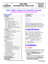
The figure below shows a typical module stack with two PC/104 modules, one PC/104 16-BIT module,
and one PC/104 8-BIT module.
The maximum number of modules is 4 in addition to the Host Board.
If standard PC/104 peripheral modules are used in a stack that includes a PC/104-Plus CPU module
and PC/104-Plus peripherals, standard PC/104 modules must be the top modules because they will
normally not include the PCI bus, while PC/104-Plus modules do.
0.6 in. (15mm) Spacers (4 plcs.)
Stackthrough
8-bit module
0.435 in. (11 mm)
0.6 in. (15 mm)
Stackthrough
16-bit module
Stackthrough
PC/104Plus module
Non-Stackthrough
PC/104Plus module
0.6 in. (15mm) Spacers (4 plcs.)
0.6 in. (15mm) Spacers (4 plcs.)
0.100 in. (2.54 mm)
0.062 in. (1.57 mm)

Configure the COM-1274: the Setup Utility
19
Configure the COM-1274: the Setup Utility
This paragraph refers to the Setup Utility revision 2.0.1; other versions may differ.
This utility is available for the COM-1274 module, and is backwardly compatible with the COM-1270.
The Setup Utility is an exe program (setup.exe) that needs to be launched from DOS (not a DOS
window) and allows the configuration of the Serial and CAN ports.
Once the Setup Utility is running the display will appear as separated into 3 areas:
• Main Menu
• Sub Menu
• Navigation / Input options
Main Menu
Sub Menu
Navigation / Input options

COM-1274 User Manual
20
COM-1274_UserMan_En_2.0
Main Menu
The Main menu shows a list with the available Sub Menus.
Sub Menu
A Sub Menu contains a list with the possible parameters you can set.
Navigation / Input options
The Navigation/Input options show you the possible actions you can perform with the currently
selected parameter/Sub Menu.
OPTION
KEY(S)
USE
Up Arrow Go to the next field above
Down Arrow Go to the next field below
Left Arrow Go to the next field to the right
Right Arrow Go to the next field to the left
Enter / Return
• Select field to modify
• Select an option i.e. “Detect Now”
• Accept a value you have entered
Escape
• Cancel a value you are entering
• Go back to the Main menu
Page Down / + Select next option in a list
Page Up / - Select previous option from a list
Numbers 0 to 9 Enter a number from 0 to 9
Backspace Erase last character entered
/