RKC INSTRUMENT GZ900 User manual

Type
User manual

This manual is also suitable for

Temperature Controller
G
Z
4
00/
G
Z900
Instruction Manual
[Part1: Hardware]
IMR03D04-E1
RKC INSTRUMENT INC.
®

All Rights Reserved, Copyright 2020, RKC INSTRUMENT INC.
NOTICE
Windows is a trademark of Microsoft Corporation.
Modbus is a registered trademark of Schneider Electric.
Company names and product names used in this manual are the trademarks or registered trademarks
of the respective companies.
This manual assumes that the reader has a fundamental knowledge of the principles of
electricity, process control, computer technology and communications.
The figures, diagrams and numeric values used in this manual are only for explanation
purpose.
RKC is not responsible for any damage or injury that is caused as a result of using this
instrument, instrument failure or indirect damage.
RKC is not responsible for any damage and/or injury resulting from the use of instruments
made by imitating this instrument.
Periodic maintenance is required for safe and proper operation of this instrument. Some
components have a limited service life, or characteristics that change over time.
Every effort has been made to ensure accuracy of all information contained herein. RKC
makes no warranty, expressed or implied, with respect to the accuracy of the information.
The information in this manual is subject to change without prior notice.
No portion of this document may be reprinted, modified, copied, transmitted, digitized, stored,
processed or retrieved through any mechanical, electronic, optical or other means without
prior written approval from RKC.
Various symbols are used on the equipment, and they have the following meaning.
: Alternating current
: Both direct and alternating current
: Reinforced insulation
: Safety precaution
This symbol is used where the instruction manual needs to be consulted for the safety of
both the operator and the equipment. Carefully read the cautions in this manual before
using the instrument.
!
IMR03D04-E1 i-1
Safety Precautions
Pictorial Symbols (safety symbols)
Various pictorial symbols are used in this manual to ensure safe use of the product, to protect
you and other people from harm, and to prevent damage to property. The symbols are
described below.
Be sure you thoroughly understand the meaning of the symbols before reading this manual.
:
This mark indicates precautions that must be
taken if there is danger of electric shock, fire,
etc., which could result in loss of life or injury.
:
This mark indicates that if these precautions
and operating procedures are not taken,
damage to the instrument may result.
: This mark indicates that all precautions
should be taken for safe usage.
To prevent injury to persons, damage to the instrument and the equipment, a
suitable external protection device shall be required.
All wiring must be completed before power is turned on to prevent electric
shock, fire or damage to the instrument and the equipment.
This instrument must be used in accordance with the specifications to prevent
fire or damage to the instrument and the equipment.
This instrument is not intended for use in locations subject to flammable or
explosive gases.
Do not touch high-voltage connections such as power supply terminals, etc. to
avoid electric shock.
RKC is not responsible if this instrument is repaired, modified or
disassembled by other than factory-approved personnel. Malfunction may
occur and warranty is void under these conditions.
IMR03D04-E1
i-2
This product is intended for use with industrial machines, test and measuring equipment.
(It is not designed for use with medical equipment and nuclear energy plant.)
This is a Class A instrument. In a domestic environment, this instrument may cause radio
interference, in which case the user may be required to take additional measures.
This instrument is protected from electric shock by reinforced insulation. Provide reinforced
insulation between the wire for the input signal and the wires for instrument power supply,
source of power and loads.
Be sure to provide an appropriate surge control circuit respectively for the following:
- If input/output or signal lines within the building are longer than 30 meters.
- If input/output or signal lines leave the building, regardless the length.
This instrument is designed for installation in an enclosed instrumentation panel. All
high-voltage connections such as power supply terminals must be enclosed in the
instrumentation panel to avoid electric shock to operating personnel.
All precautions described in this manual should be taken to avoid damage to the instrument or
equipment.
If the equipment is used in a manner not specified by the manufacturer, the protection provided
by the equipment may be impaired.
All wiring must be in accordance with local codes and regulations.
To prevent instrument damage as a result of failure, protect the power line and the input/output
lines from high currents with a suitable overcurrent protection device with adequate breaking
capacity such as a fuse, circuit breaker, etc.
A malfunction in this product may occasionally make control operations impossible or prevent
alarm outputs, resulting in a possible hazard. Take appropriate measures in the end use to
prevent hazards in the event of malfunction.
Prevent metal fragments or lead wire scraps from falling inside instrument case to avoid electric
shock, fire or malfunction.
Tighten each terminal screw to the specified torque found in the manual to avoid electric shock,
fire or malfunction.
For proper operation of this instrument, provide adequate ventilation for heat dissipation.
Do not connect wires to unused terminals as this will interfere with proper operation of the
instrument.
Turn off the power supply before cleaning the instrument.
Do not use a volatile solvent such as paint thinner to clean the instrument. Deformation or
discoloration may occur. Use a soft, dry cloth to remove stains from the instrument.
To avoid damage to the instrument display, do not rub with an abrasive material or push the
front panel with a hard object.
When disposing of each part used for this instrument, always follows the procedure for
disposing of industrial wastes stipulated by the respective local community.
For Proper Disposal
IMR03D04-E1
i-3
Symbols
Pictorial Symbols (safety symbols)
: This mark indicates important information on installation, handling
and operating procedures.
: This mark indicates supplemental information on installation,
handling and operating procedures.
: This mark indicates where additional information may be located.
Character Symbols
11-segment character
0 1 2 3 4 5 6 7 8 9
Minus Period
0 1 2 3 4 5 6 7 8 9 - .
A B (b) C c D (d) E F G H I J K
A b C c D E F G H I J K
L M N n O (o) P Q R S T t U
L M N n o P Q R S T t U
u V W X Y Z
Degree
Prime
(Asterisk)
u V W X Y Z
@
/ ` Š ‹
7-segment character
0 1 2 3 4 5 6 7 8 9
Minus Period
0 1 2 3 4 5 6 7 8 9 - .
A B (b) C c D (d) E F G H I J K
A b C c D E F G H I J K
L M N (n) O (o) P Q R S T t U u
L M n o P Q R S T t U u
V W X Y Z
Degree
Prime
(Asterisk)
V W X Y Z
@
` Š
IMR03D04-E1
i-4
Abbreviation symbols
These abbreviations are used in this manual:
Abbreviation
symbols
Name
Abbreviation
symbols
Name
PV Measured value TC (input) Thermocouple (input)
SV Set value RTD (input) Resistance temperature detector (input)
MV Manipulated output value V (input) Voltage (input)
AT Autotuning I (input) Current (input)
ST Startup tuning HBA (1, 2) Heater break alarm (1, 2)
OUT (1 to 3) Output (1 to 3) CT (1, 2) Current transformer (1, 2)
DI (1 to 6) Digital input (1 to 6) LBA Control loop break alarm
DO (1 to 4) Digital output (1 to 4) LBD LBA deadband
Screens used in this manual
It should be noted that this manual describes various screens of GZ400/900 according to the
following rules.
GZ400/900 are available in two types: single input type and dual input type.
The dual input type is further categorized into two types: Dual PV type and PV Remote
setting type. For a dual input model, the same parameter may exist in both Input 1 and Input
2. “1.” or “2.” is added to the top of the parameters for identification. “1.” is not added to the
top of the parameters list for the single input type.
[Display example of the dual input type]
[Display example of a single input type]
This manual uses the dual inputs for explanation. For other types such as a single input
type, ignore the first character “1.” at the top of the parameter.
The parameters used only on the dual input type are displayed in the colored background.
[Notation in this manual]
Set value (SV)
1. SV
1. SV
Input 1_Set value (SV) Input 2_Set value (SV)
2. SV
Parameter shown
only on the dual
input type
Input 2_Set value (SV)
2. SV
Input 1_Set value (SV)
1. SV
This part is not
displayed on the
single input type.
IMR03D04-E1
i-5
Document Configuration
There are seven manuals pertaining to this product. Please be sure to read all manuals
specific to your application requirements.
The following manuals can be downloaded from the official RKC website:
https://www.rkcinst.co.jp/english/download-center/
Manual
Manual
Number
Remarks
GZ400/GZ900 Installation Manual IMR03D01-E This manual is enclosed with instrument.
This manual explains the mounting and wiring.
GZ400/GZ900 Quick Operation Manual IMR03D02-E This manual is enclosed with instrument.
This manual explains the basic key operation,
mode menu, and data setting.
GZ400/GZ900 Parameter List IMR03D03-E This manual is enclosed with instrument.
This list is a compilation of the parameter data
of each mode.
GZ400/GZ900 Instruction Manual
[Part 1: Hardware]
IMR03D04-E1
This manual you are reading now.
This manual describes installation, wiring,
troubleshooting and product specification.
GZ400/GZ900 Instruction Manual
[Part 2: Parameters/Functions]
IMR03D05-E Parameters:
This manual describes how to switch the
operation modes and parameters, the range of
parameters, and initialization/automatic
conversion associated with the change of
settings.
Functions:
This manual describes how to set up and each
function.
GZ400/GZ900 Instruction Manual
[Host Communication]
IMR03D07-E This manual explains RKC communication
protocol (ANSI X3.28-1976) and Modbus
relating to communication parameters setting.
GZ400/GZ900 Instruction Manual
[PLC Communication]
IMR03D08-E This manual describes how to set up the
instrument for communication with a
programmable controller (PLC).
Read this manual carefully before operating the instrument. Please place the manual
in a convenient location for easy reference.
IMR03D04-E1
i-6
About This Manual
This manual consists of the following 7 chapters and index; Parts description, Model code, Mounting,
Wiring and other basic handling of the instrument. If you are looking for basic handling information,
you may be able to find one in the following table of contents.
[This manual (Part1: Hardware)]
What do you want to do?
See the following section
for more details
I want to check the features, the instrument, and the model code. 1. OUTLINE
I want to check the mounting caution and how to mount and remove. 2. MOUNTING *
I want to check the external dimensions and the panel cutout details 2. MOUNTING *
I want to check wiring caution, terminal layout, wiring to each terminal, etc. 3. WIRING *
I want to check the connection information of the loader communication. 3. WIRING *
I want to check how to use terminal covers (optional). 3. WIRING
I want to check the front appearance.
4. PARTS DESCRIPTION
AND
BASIC OPERATION *
I want to check the modes available.
I want to know the basic operation such as setting a set value.
I want to know what to do when I use the instrument for the first time. 5. OPERATION *
I want to know the error indications and the error codes. 6. TROUBLESHOOTING *
I want to know what actions I should take in case of errors. 6. TROUBLESHOOTING
I want to check the instrument information (ROM version, model code,
instrument number).
6. TROUBLESHOOTING
I want to know the specification of the instrument. 7. SPECIFICATIONS *
I want to know how to replace a waterproof/dustproof gasket (optional) A. APPENDIX
I want to know the external dimension of the current transformer (CT). A. APPENDIX
* Checking is possible using a concise manual supplied with the product.
[Major topics contained in other manuals]
What do you want to do?
See the following section
for more details
I want to know the functions and how to use them. [Part 2: Parameters/Functions]
I want to check the parameter names and their setting range. [Part 2: Parameters/Functions]
Parameter List (This manual
is enclosed with instrument.)
I want to know how to connect this instrument to a host computer. [Host Communication]
I want to know how to connect this instrument to a programmable logic
controller (PLC).
[PLC Communication]
IMR03D04-E1
i-7
Contents
Page
NOTICE
Safety Precautions ............................................................................................................................... i-1
Pictorial Symbols (safety symbols) .............................................................................................. i-1
WARNING ....................................................................................................................................... i-1
CAUTION ........................................................................................................................................ i-2
For Proper Disposal .............................................................................................................................. i-2
Symbols ................................................................................................................................................ i-3
Pictorial Symbols (safety symbols) .............................................................................................. i-3
Character Symbols ...................................................................................................................... i-3
Abbreviation symbols ................................................................................................................... i-4
Screens used in this manual ....................................................................................................... i-4
Document Configuration ....................................................................................................................... i-5
About This Manual ................................................................................................................................ i-6
1. OUTLINE ............................................................................ 1-1
Chapter 1 describes features, package contents, model code, etc.
1.1 Features ....................................................................................................... 1-2
1.2 Checking the Product ................................................................................... 1-3
1.3 Model Code .................................................................................................. 1-4
1.3.1 Suffix code ...................................................................................................................... 1-4
1.3.2 Quick start code (Initial setting code) .............................................................................. 1-6
1.3.3 Range Code Table .......................................................................................................... 1-8
2. MOUNTING ........................................................................ 2-1
Chapter 2 describes mounting cautions, dimensions and mounting procedures.
2.1 Mounting Cautions ........................................................................................ 2-2
2.2 Dimensions ................................................................................................... 2-3
2.3 Procedures of Mounting and Removing ....................................................... 2-4
The mounting position of the mounting brackets ............................................................. 2-4
Mounting procedures (Standard type) ............................................................................. 2-5
Mounting procedures (Waterproof/Dustproof type) ......................................................... 2-6
Removal procedures ........................................................................................................ 2-7
IMR03D04-E1
i-8
Page
3. WIRING .............................................................................. 3-1
Chapter 3 describes wiring cautions, wiring layout and wiring of terminals.
3.1 Wiring Cautions ............................................................................................ 3-2
3.2 Terminal Layout ............................................................................................ 3-5
GZ400 .............................................................................................................................. 3-5
GZ900 .............................................................................................................................. 3-6
Isolations of input and output ........................................................................................... 3-7
3.3 Wiring of Each Terminal ............................................................................... 3-8
3.3.1 Power supply ................................................................................................................... 3-8
3.3.2 Measured input 1 (Thermocouple/RTD/Voltage/Current) ............................................... 3-9
3.3.3 Output 1 (OUT1)/Output 2 (OUT2)................................................................................ 3-10
3.3.4 Digital output (DO1/DO2/DO3/DO4) ............................................................................. 3-12
3.3.5 Option 1 ......................................................................................................................... 3-14
Option 1: T, U, V
[Current transformer input 1 (CT1), Current transformer input 2 (CT2)] ........................ 3-14
3.3.6 Option 2 ......................................................................................................................... 3-16
Option 2: A [Output 3 (OUT3)] ....................................................................................... 3-16
Option 2: B [Digital input 1 to 6 (DI1 to DI6)] ................................................................. 3-18
Option 2: C [Communication (RS-422A)] ....................................................................... 3-19
Option 2: D [Communication (RS-485)] ......................................................................... 3-23
Option 2: E [Output 3 (OUT3), Digital input 1 to 6 (DI1 to DI6)] .................................... 3-27
Option 2: F [Output 3 (OUT3), Communication (RS-422A)] .......................................... 3-29
Option 2: G [Output 3 (OUT3), Communication (RS-485)] ............................................ 3-31
Option 2: H
[Output 3 (OUT3), Digital input 1 to 4 (DI1 to DI4), Communication (RS-422A)] .......... 3-33
Option 2: J
[Output 3 (OUT3), Digital input 1 to 6 (DI1 to DI6), Communication (RS-485)] ............. 3-36
3.3.7 Option 3 ......................................................................................................................... 3-39
Option 3: 1 [Remote setting input] ................................................................................. 3-39
Option 3: 2 [Measured input 2] ....................................................................................... 3-40
3.4 Connections for Loader Communication .................................................... 3-42
3.5 Handling of the Terminal Cover [Optional] .................................................. 3-44
Mounting procedures ..................................................................................................... 3-44
Removing procedures .................................................................................................... 3-45
IMR03D04-E1
i-9
Page
4. PARTS DESCRIPTION AND BASIC OPERATION .......... 4-1
Chapter 4 describes name of parts, switching modes, setting and modifying values and other basic
operations.
4.1 Parts Description .......................................................................................... 4-2
4.2 Mode Switching ............................................................................................ 4-5
4.3 Changing Set Value ...................................................................................... 4-6
4.4 Operation of the Direct Key (FUNC key) ...................................................... 4-7
4.5 Protecting Setting Data ................................................................................. 4-8
5. OPERATION ...................................................................... 5-1
Chapter 5 describes caution for first time use, parameter setting required before operation, and others.
5.1 Operating Precautions .................................................................................. 5-2
5.2 Setup Procedures ......................................................................................... 5-3
5.3 Initial Setup Before Operation ....................................................................... 5-4
5.3.1 Setting Power Supply Frequency ........................................................................................... 5-5
5.3.2 Initial setting of setup example 1 (Setting parameters related to the event) ................... 5-6
5.3.3 Initial setting of setup example 2
(Setting parameters related to the input, control, output and event) .............................. 5-8
5.4 Setting the Control Set Value [Set value (SV)] ........................................... 5-11
5.5 Setting the Event Set Value ........................................................................ 5-12
5.6 Tuning the PID Parameters (Execution of AT) ............................................ 5-14
6. TROUBLESHOOTING ....................................................... 6-1
Chapter 6 describes Error displays and countermeasures for errors.
6.1 Error Displays ............................................................................................... 6-2
Input error displays........................................................................................................... 6-2
Self-diagnostic error ......................................................................................................... 6-4
6.2
Solutions for Problems .................................................................................. 6-5
Display related errors ....................................................................................................... 6-6
Control related errors ....................................................................................................... 6-7
Operation related errors ................................................................................................... 6-9
Event related errors ....................................................................................................... 6-10
Control loop break alarm (LBA) related errors ............................................................... 6-11
Heater break alarm (HBA) related errors ....................................................................... 6-11
Communication related errors ........................................................................................ 6-12
6.3 Verifying Instrument Information ................................................................. 6-14
How to display the information ....................................................................................... 6-14
How to check .................................................................................................................. 6-15
IMR03D04-E1
i-10
Page
7. SPECIFICATIONS ............................................................. 7-1
A. APPENDIX........................................................................ A-1
A.1 Replacing the Waterproof/Dustproof Gasket [Optional] ............................. A-2
A.2 Current Transformer (CT) Dimensions [Optional] ...................................... A-5
OUTLINE
IMR03D04-E1 1-1
This chapter describes features, package contents, model code, etc.
1.1 Features ........................................................................................... 1-2
1.2 Checking the Product ....................................................................... 1-3
1.3 Model Code ...................................................................................... 1-4
1.3.1 Suffix code ....................................................................................................... 1-4
1.3.2 Quick start code (Initial setting code) ............................................................... 1-6
1.3.3 Range Code Table ........................................................................................... 1-8
1. OUTLINE
1-2 IMR03D04-E1
1.1 Features
This high performance digital controller has the following features:
Main settings such as PID, event, and control relate
d
settings can be stored in up to 16 areas (Memory are
a
function).
The use of this function offers:
Simple ramp/soak control *
Simple sequence operation *
Control using Level PID *
* For details, refer to the separate manual [Part 2].
Versatile memory area function
The following control types are available.
Remote setting input
*
2-loop control
*
Differential temperature control
*
Control with PV select
*
* For details, refer to the separate manual [Part 2].
Dual loop control is available (optional)
Suppresses overshoot at startup (at power on, STOP
to RUN), set value (SV) change, and occurrence of
external disturbances
*
Suppresses overshoot during the transition from
ramp to soak when Setting change rate limiter is
used *
Suppresses the bottom at the occurrence of external
disturbances caused by Feedforward *
* For details, refer to the separate manual [Part 2].
Can handle various external disturbances
Loader communication connector is supplied as
standard on the front panel (GZ400/900). Using ou
r
USB communication converter (COM-K2) and ou
r
communication tool (PROTEM2)*, the loade
r
communication is possible to easily store and copy the
set values.
* Download the software from the official RKC website:
https://www.rkcinst.co.jp/english/download-center
When Communication interface
1
and communicatio
n
protocol
2
are specified at the time of order, any one o
f
the following communication functions is possible.
- Host communication to an upper system
3
- PLC communication to MITSUBISHI MELSEC
series
4
1
RS-485, RS-422A
2
RKC communication (ANSI X3.28-1976), Modbus-RTU,
MITSUBISHI MELSEC series special protocol
(QnA-compatible 3C frame format 4)
3
For details, refer to the separate manual [Host Communication].
4
For details, refer to the separate manual [PLC Communication].
Communication
Output signal (control output, retransmission output,
logic calculation output, and instrument status output)
is freely assignable to each output of GZ400/900
(OUT: max. 3, DO: max. 4). *
* For details, refer to the separate manual [Part 2].
Freely assignable outputs
PID control (Reverse action)
1
PID control (Direct action)
1
Heat/Cool PID control (for Extruder [air cooling])
1
Heat/Cool PID control (for Extruder [water cooling])
1
Heat/Cool PID control (Cooling linear type)
1
ON/OFF action
2
Manual control
3
1
Specify when ordering
2
Proportional band [heat-side] must be set to zero.
3
Switch the mode to Manual mode using Auto/Manual transfer
Cope with various control applications
Function assignable key (FUNC key) *
GZ400/900 are supplied with a FUNC key to which
specific function can be assigned. Assigning a functio
n
to the FUNC key realizes a direct access.
Desired screens can be grouped for easy access *
Up to 16 desired screens can be registered as one mode
(Parameter select function).
* For details, refer to the separate manual [Part 2].
Improved operatability
1. OUTLINE
IMR03D04-E1
1-3
1.2 Checking the Product
Before using this product, check each of the following:
Model code
Check that there are no scratches or breakage in external appearance (case, front panel, or terminal, etc.)
Check that all of the items delivered are complete. (Refer to below)
Accessories Q’TY Remarks
Instrument 1

Mounting bracket (with screw) 2 GZ900 Waterproof/Dustproof type: 4
GZ400/GZ900 Installation Manual
(IMR03D01-E)
1 Enclosed with instrument
GZ400/GZ900 Quick Operation Manual
(IMR03D02-E)
1 Enclosed with instrument
GZ400/GZ900 Parameter List
(IMR03D03-E)
1 Enclosed with instrument
GZ400/GZ900 Instruction Manual
[Part 1: Hardware]
(IMR03D04-E1)
1 This manual
(sold
separately)
This manual can be downloaded from
the official RKC website:
https://www.rkcinst.co.jp/english/
download-center/
GZ400/GZ900 Instruction Manual
[Part 2: Parameters/Functions]
(IMR03D05-E)
1 Sold
separately
GZ400/GZ900 Instruction Manual
[Host Communication]
(IMR03D07-E)
1 Sold
separately
GZ400/GZ900 Instruction Manual
[PLC Communication]
(IMR03D08-E)
1 Sold
separately
Gasket
KFZ400-317 (GZ400)
KFZ900-317 (GZ900)
1 Optional
(Waterproof/Dustproof type)
Terminal cover
KFB400-58 (GZ400/900)
Depending
on the order
quantity
Optional (sold separately)
Front cover
KRB400-36 (GZ400)
KRB900-36 (GZ900)
Depending
on the order
quantity
Optional (sold separately)
CT (Current transformer for heater break alarm)
CTL-6-P-Z [for 0.0 to 10.0 A]
CTL-6-P-N [for 0.0 to 30.0 A]
CTL-12-S56-10L-N [for 0.0 to 100.0 A]
Depending
on the order
quantity
Optional (sold separately)
If any of the above are missing, damaged, or if your manual is incomplete, please contact RKC
sales office or the agent.
1. OUTLINE
IMR03D04-E1
1-4
1.3 Model Code
Check that the product received is correctly specified by referring to the following model code list:
If the product is not identical to the specifications, please contact RKC sales office or the agent.
1.3.1 Suffix code
□□□-□ □*□
/
(1) (2) (3) (4) (5) (6) (7) (8) (9) (10) (11) (12)
Specification
Suffix code
(1) (2) (3) (4) (5) (6) (7) (8) (9) (10) (11) (12)
PID control with AT (Reverse action) F
PID control with AT (Direct action) D
Heat/Cool PID control with AT G
Control method Heat/Cool PID control with AT (for Extruder [air cooling]) A
Heat/Cool PID control with AT (for Extruder [water cooling]) W
Measured input
and Range
Refer to Range Code Table (P. 1-8) 
Output 1
(OUT1)
1
None N
Relay contact output M
Voltage pulse output (0/12 V DC) V
Continuous voltage output (0 to 5 V DC) 4
Continuous voltage output (0 to 10 V DC) 5
Continuous voltage output (1 to 5 V DC) 6
Current output (0 to 20 mA DC) 7
Current output (4 to 20 mA DC) 8
Transistor output B
Output 2
(OUT2)
1
None
N
Relay contact output M
Voltage pulse output (0/12 V DC) V
Continuous voltage output (0 to 5 V DC) 4
Continuous voltage output (0 to 10 V DC) 5
Continuous voltage output (1 to 5 V DC) 6
Current output (0 to 20 mA DC) 7
Current output (4 to 20 mA DC) 8
Transistor output B
Power supply
voltage
24 V AC/DC 3
100 to 240 V AC 4
Digital output
(DO)
1
Digital output [1 point] (DO1)
1
Digital output [4 points] (DO1 to DO4) 4
Option 1
2
None N
CT input [2 points] (CT1, CT2) [CTL-6-P-N] T
CT input [2 points] (CT1, CT2) [CTL-12-S56-10L-N] U
CT input [2 points] (CT1, CT2) [CTL-6-P-Z] V
Option 2
3
None
N
Output 3 (OUT3) A
Digital input [6 points] (DI1 to DI6) B
Communication (RS-422A) C
Communication (RS-485) D
Output 3 (OUT3)
Digital input [6 points] (DI1 to DI6) E
Output 3 (OUT3)
Communication (RS-422A) F
Output 3 (OUT3)
Communication (RS-485) G
Output 3 (OUT3)
Digital input [4 points] (DI1 to DI4)
Communication (RS-422A) H
Output 3 (OUT3)
Digital input [6 points] (DI1 to DI6)
Communication (RS-485) J
Option 3
4, 5
None N
Remote setting input 1
Measured input 2 2
Display color Standard N
White 1
Waterproof/
Dustproof
(optional)
None N
Waterproof/Dustproof (IP65) 1
Quick start
code
1
Quick start code not specified
N
Specify quick start code 1
GZ400
GZ900
1. OUTLINE
IMR03D04-E1
1-5
1
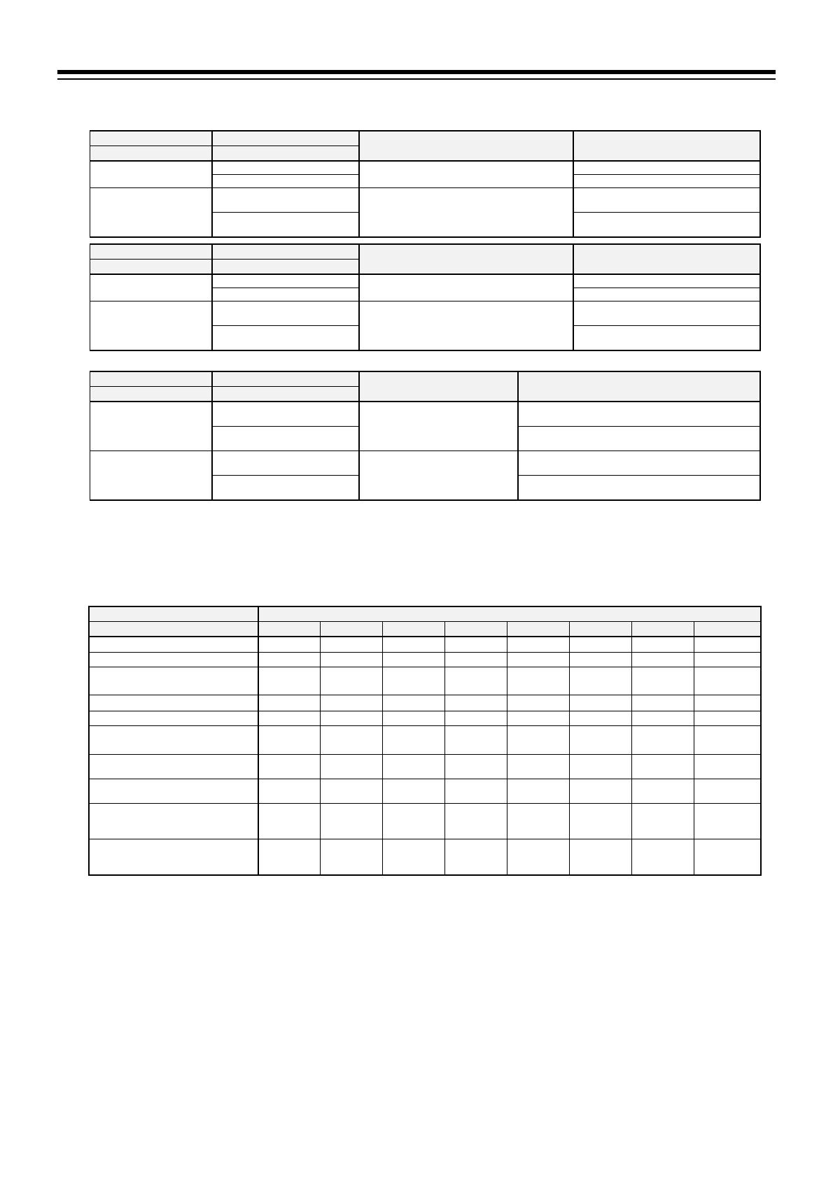
The factory set values of Output 1 (OUT1), Output 2 (OUT2), and Digital output will be as follows depending on the suffix code and
the initial setting code.
(3) Output 1 (OUT1) (12) Quick start code
Factory set value Remarks
Suffix code Suffix code
N: None
N: Quick start code not specified
No output assignment to OUT1
1: Specify quick start code
Other than
N
N: Quick start code not specified
Input 1_Control output
(Heat/Cool PID control: Heat-side)
To be shipped with the output assignment
code “1” in the Initial setting code (P. 1-6)
1: Specify quick start code
Depends on the output assignment code in
the Initial setting code (P. 1-6)
(4) Output 2 (OUT2) (12) Quick start code
Factory set value Remarks
Suffix code Suffix code
N: None
N: Quick start code not specified
No output assignment to OUT2
1: Specify quick start code
Other than
N
N: Quick start code not specified
Heater break alarm 1 (HBA1) output
Heater break alarm 2 (HBA2) output
(*)
To be shipped with the output assignment
code “1” in the Initial setting code (P. 1-6)
1: Specify quick start code
Depends on the output assignment code in
the Initial setting code (P. 1-6)
(*) The content of the assignment depends on the control action and the selection of Option 3. (Refer to P. 1-7)
(6) Digital output (DO) (12) Quick start code
Factory set value Remarks
Suffix code Suffix code
1: Digital output [1 point]
(DO1)
N: Quick start code not specified
DO1: Event 1
DO2 to DO4: No assignment
To be shipped with the output assignment code “1” in the
Initial setting code (P. 1-6)
1: Specify quick start code
Depends on the output assignment code in the Initial
setting code (P. 1-6)
4: Digital output [4 points]
(DO1 to DO4)
N: Quick start code not specified
DO1: Event 1
DO2: Event 2
DO3: Event 3
DO4: Event 4
To be shipped with the output assignment code “1” in the
Initial setting code (P. 1-6)
1: Specify quick start code
Depends on the output assignment code in the Initial
setting code (P. 1-6)
2
When “CT input [2 points] (CT1, CT2)” is specified at Option 1, the instrument will be shipped configured as follows.
CT1
assignment: Output 1 (OUT1)
CT2 assignment: Depends on the control action type.
PID control (without Measured input 2): Output 1 (OUT1) Heat/Cool PID control: Output 2 (OUT2)
PID control (with Measured input 2): Output 2 (OUT2)
3
Depending on the designation of the suffix code, the factory set values of Output3 (OUT3), Digital input, and Communication in
Option 2 will be as follows.
(8) Option 2 Factory set value
Suffix code DI1 DI2 DI3 DI4 DI5 DI6 OUT3 Communication
N: None
A: Output 3 (OUT3) (NOTE 1)
B: Digital input [6 inputs] (DI1 to DI6)
Area 8 points
(**)
Area 8 points
(**)
Area 8 points
(**)
RUN/STOP
transfer *
Auto/Manual
transfer **
Interlock
release
C: Communication (RS-422A) (NOTE 2)
D: Communication (RS-485) (NOTE 2)
E: Output 3 (OUT3)
Digital input [6 inputs] (DI1 to DI6)
Area 8 points
(**)
Area 8 points
(**)
Area 8 points
(**)
RUN/STOP
transfer *
Auto/Manual
transfer **
Interlock
release
(NOTE 1)
F: Output 3 (OUT3)
Communication (RS-422A)
(NOTE 1) (NOTE 2)
G: Output 3 (OUT3)
Communication (RS-485)
(NOTE 1) (NOTE 2)
H: Output 3 (OUT3)
Digital input
[4 inputs] (DI1 to DI4)
Communication (RS-422A)
Area 8 points
(**)
Area 8 points
(**)
Area 8 points
(**)
RUN/STOP
transfer *
(NOTE 1) (NOTE 2)
J: Output 3 (OUT3)
Digital input
[6 inputs] (DI1 to DI6)
Communication (RS-485)
Area 8 points
(**)
Area 8 points
(**)
Area 8 points
(**)
RUN/STOP
transfer *
Auto/Manual
transfer **
Interlock
release
(NOTE 1) (NOTE 2)
(**): Without area set signal
* When “1: Remote setting input” is specified at Option 3, this will be configured to “Remote/Local transfer”.
**
When “2: Measured input 2” is specified at Option 3, “Auto/Manual transfer” will be assigned to Input 1 and Input 2.
(NOTE 1) Output 3 (OUT3) will be factory preset as follows.
Universal output type selection
(OUT3) (UNIo): Current output (4 to 20 mA DC)
OUT3 function selection (oSL3): Retransmission output
Retransmission output 3 type (Ao3): Input 1_Measured value (PV)
(NOTE 2) When “N: Quick start code not specified” is specified in the Initial setting code, the protocol of “Communication (RS-422A)” and
“Communication (RS-485)” at Option 2 type will be factory preset to RKC communication (ANSI X3.28-1976). The digit of the communication
data depends on the Input range code.
4
When Heat/Cool PID control is specified at Control action, “2: Measured input 2” in
the Specification code is not selectable.
5
When “Remote setting input” or “Measured input 2” is specified at OUT3 the instrument will be shipped configured as follows.
Remote setting input: The factory set value of the Remote setting input depends on the designation at “Remote setting input type” in
the Initial setting code. When “N: Quick start code not specified” is specified in the Initial setting code, the
Remote setting input type will be factory preset to “0 to 10V DC” (Input range is the same as Measured input 1).
Measured input 2: Select function for input 2 (2PV) will be shipped configured as “2-loop control.”
The default value of the Input range and the Control action will be the same as Measured input 1.
1. OUTLINE
IMR03D04-E1
1-6
1.3.2 Quick start code (Initial setting code)
Quick start code tells the factory to ship with each parameter preset to the values detailed as specified by the
customer. Quick start code is not necessarily specified when ordering, unless the preset is requested.
These parameters are software selectable items and can be re-programmed in the field following procedures
found in the manual.
□-□ □-□
(1) (2) (3) (4) (5) (6) (7)
Specification
Initial setting code
(1) (2) (3) (4) (5) (6) (7)
Output assignment
OUT1, OUT2, DO1 to DO4
[Refer to Output Assignment Code Table (P. 1-7)]
Remote setting input
type
a
None
N
Voltage input (0 to 1 V DC)
3
Voltage input (0 to 5 V DC)
4
Voltage input (0 to 10 V DC)
5
Voltage input (1 to 5 V DC)
6
Current input (0 to 20 mA DC)
7
Current input (4 to 20 mA DC)
8
Voltage input (5 to 5 V DC)
9
Voltage input (10 to 10 V DC)
A
Event 1 type
b, c
None N
Deviation high A
Deviation low B
Deviation high/low C
Band D
Deviation high with hold action E
Deviation low with hold action F
Deviation high/low with hold action G
Process high H
Process low J
Process high with hold action K
Process low with hold action L
Deviation high with re-hold action Q
Deviation low with re-hold action R
Deviation high/low with re-hold action T
Band (High/low individual setting) U
SV high V
SV low W
Deviation high/low (High/low individual setting) X
Deviation high/low with hold action (High/low individual setting) Y
Deviation high/low with re-hold action (High/low individual setting) Z
MV high 1
MV low 2
MV high (Cool-side) 3
MV low (Cool-side) 4
Event 2 type
b, c
None N
Event 2 type (The code is same as Event 1 type)
Event 3 type
b, c
None
N
Event 3 type (The code is same as Event 1 type)
Event 4 type
b, c
None N
Event 4 type (The code is same as Event 1 type)
Communication
protocol
d
None
N
RKC communication (ANSI X3.28-1976) 1
Modbus 2
PLC communication: MITSUBISHI MELSEC series special protocol (QnA-compatible 3C frame format 4) 3
a
When “Remote setting input” is not specified as an option, only “N: None” is selectable.
b
When the designation in the Initial setting code is “N: Quick start code not specified,” the instrument will be shipped with the configuration of
“A: Deviation high.”
c
The input assignment of the event will be configured as “Input 1.”
d
When “Communication” is not specified as an option, only “N: None” is selectable as the communication protocol.
1. OUTLINE
IMR03D04-E1
1-7
Output Assignment Code Table
Code OUT1 OUT2 * DO1 DO2 DO3 DO4
1 MV1 HBA1/HBA2 EV1 EV2 EV3 EV4
2 MV1 HBA1/HBA2 EV1 LBA1/LBA2 EV3 EV4
3 MV1 FAIL EV1 HBA1/HBA2 EV3 LBA1/LBA2
4 MV1 HBA1/HBA2 EV1 FAIL EV3 EV4
5 MV1 EV1 LBA1/LBA2 HBA1/HBA2 EV3 EV4
6 MV1 HBA1/HBA2 LBA1/LBA2 FAIL EV3 EV4
7 MV1 EV1 HBA1/HBA2 FAIL EV3 EV4
8 MV1 EV2/EV4 EV1/EV3 HBA1/HBA2 LBA1/LBA2 FAIL
MV1: Input 1_Control output (Heat/Cool PID control: Heat-side)
HBA1: Heater break alarm 1 (HBA1) output EV1: Event 1 output
HBA2: Heater break alarm 2 (HBA2) output EV2: Event 2 output
LBA1: Control loop break alarm 1 (LBA1) output EV3: Event 3 output
LBA2: Control loop break alarm 2 (LBA2) output EV4: Event 4 output
FAIL: FAIL output
If two or more items are assigned to the same output, the resultant output is OR.
* OUT2 assignment
The output assignment depends on the Control action and the selection of Option 3.
Control action Option 3 OUT2 assignment
PID control
Option 3: None
or
Remote setting input
One item from the above
Output Assignment Code Table.
Measured input 2 Input 2_Control output
Heat/Cool PID control
Option 3: None
or
Remote setting input
Input 1_Control output
Heat/Cool PID control: Cool-side
1. OUTLINE
IMR03D04-E1
1-8
1.3.3 Range Code Table
The input range can be changed later within the range of the input range table
*
even if the input
range is specified at the time of order.
* Refer to the separate manual [Part 2: Parameters/Functions].
Thermocouple (TC) input
Input type Code Range See Note Input type Code Range See Note
K K01 0 to 200 C 5 T T01 199.9 to 400.0 C 5
K02 0 to 400 C 5 T02 199.9 to 100.0 C 5
K03 0 to 600 C 5 T03 100.0 to 200.0 C 5
K04 0 to 800 C 5 T19 200.0 to 400.0 C 5
K06 0 to 1200 C 5 R R01 0 to 1600 C 5
K07 0 to 1372 C 5 R07 50 to 1768 C 5
K08 199.9 to 300.0 C 5 R08 50.0 to 1768.0 C 5
K09 0.0 to 400.0 C 5 R09 0.0 to 1600.0 C 5
K10 0.0 to 800.0 C 5 S S06 50 to 1768 C 5
K14 0 to 300 C 5 S07 50.0 to 1768.0 C 5
K41 200 to 1372 C 5 B B03 0 to 1800 C 5
K42 200.0 to 1372.0 C 5 B04 0.0 to 1800.0 C 5
KA1 0 to 800 F 5 E E01 0 to 800 C 5
KA2 0 to 1600 F 5 E23 0.0 to 800.0 C 5
KA3 0 to 2502 F 5 N N02 0 to 1300 C 5
J J01 0 to 200 C 5 N05 0.0 to 1300.0 C 5
J02 0 to 400 C 5 W5Re/
W26Re
W03 0 to 2300 C 5
J03 0 to 600 C 5
J04 0 to 800 C 5 PL II A01 0 to 1300 C 5
J08 0.0 to 400.0 C 5 A05 0.0 to 1300.0 C 5
J29 200.0 to 1200.0 C 5 U U01 199.9 to 600.0 C 5
JA1 0 to 800 F 5 L L04 0.0 to 900.0 C 5
JA3 0 to 2192 F 5 PR40-20 F02 0 to 1800 C 5
JA6 0 to 400 F 5 FA2 0 to 3200 F 5
RTD input
Input type Code Range See Note Input type Code Range See Note
Pt100 D01 199.9 to 649.0 C 5 Pt100 D21 200.0 to 200.0 C 5
D04 100.0 to 100.0 C 5 D27 0.00 to 50.00 C 5
D05 100.0 to 200.0 C 5 D34 100.00 to 100.00 C 5
D06 0.0 to 50.0 C 5 D35 200.0 to 850.0 C 5
D07 0.0 to 100.0 C 5 DA1 199.9 to 999.9 F 5
D08 0.0 to 200.0 C 5 DA9 0.0 to 500.0 F 5
D09 0.0 to 300.0 C 5 JPt100 P08 0.0 to 200.0 C 5
D10 0.0 to 500.0 C 5 P29 100.00 to 100.00 C 5
D12 199.9 to 600.0 C 5 P30 200.0 to 640.0 C 5
Voltage/Current input
Input type Code Range See Note Input type Code Range See Note
0 to 10 mV DC 101 Programmable
range
19999 to 99999
Factory set value
0.0 to 100.0
5 1 to 5 V DC 601
Programmable
range
19999 to 99999
Factory set value
0.0 to 100.0
5
0 to 100 mV DC 201 5 0 to 20 mA DC 701 5
0 to 1 V DC 301 5 4 to 20 mA DC 801 5
0 to 5 V DC 401 5 10 to 10 V DC 904 5
0 to 10 V DC 501 5 5 to 5 V DC 905 5
Note The number of displayed digits of the measured value.
  • Page 1 1
  • Page 2 2
  • Page 3 3
  • Page 4 4
  • Page 5 5
  • Page 6 6
  • Page 7 7
  • Page 8 8
  • Page 9 9
  • Page 10 10
  • Page 11 11
  • Page 12 12
  • Page 13 13
  • Page 14 14
  • Page 15 15
  • Page 16 16
  • Page 17 17
  • Page 18 18
  • Page 19 19
  • Page 20 20
  • Page 21 21
  • Page 22 22
  • Page 23 23
  • Page 24 24
  • Page 25 25
  • Page 26 26
  • Page 27 27
  • Page 28 28
  • Page 29 29
  • Page 30 30
  • Page 31 31
  • Page 32 32
  • Page 33 33
  • Page 34 34
  • Page 35 35
  • Page 36 36
  • Page 37 37
  • Page 38 38
  • Page 39 39
  • Page 40 40
  • Page 41 41
  • Page 42 42
  • Page 43 43
  • Page 44 44
  • Page 45 45
  • Page 46 46
  • Page 47 47
  • Page 48 48
  • Page 49 49
  • Page 50 50
  • Page 51 51
  • Page 52 52
  • Page 53 53
  • Page 54 54
  • Page 55 55
  • Page 56 56
  • Page 57 57
  • Page 58 58
  • Page 59 59
  • Page 60 60
  • Page 61 61
  • Page 62 62
  • Page 63 63
  • Page 64 64
  • Page 65 65
  • Page 66 66
  • Page 67 67
  • Page 68 68
  • Page 69 69
  • Page 70 70
  • Page 71 71
  • Page 72 72
  • Page 73 73
  • Page 74 74
  • Page 75 75
  • Page 76 76
  • Page 77 77
  • Page 78 78
  • Page 79 79
  • Page 80 80
  • Page 81 81
  • Page 82 82
  • Page 83 83
  • Page 84 84
  • Page 85 85
  • Page 86 86
  • Page 87 87
  • Page 88 88
  • Page 89 89
  • Page 90 90
  • Page 91 91
  • Page 92 92
  • Page 93 93
  • Page 94 94
  • Page 95 95
  • Page 96 96
  • Page 97 97
  • Page 98 98
  • Page 99 99
  • Page 100 100
  • Page 101 101
  • Page 102 102
  • Page 103 103
  • Page 104 104
  • Page 105 105
  • Page 106 106
  • Page 107 107
  • Page 108 108
  • Page 109 109
  • Page 110 110
  • Page 111 111
  • Page 112 112
  • Page 113 113
  • Page 114 114
  • Page 115 115
  • Page 116 116
  • Page 117 117
  • Page 118 118
  • Page 119 119
  • Page 120 120
  • Page 121 121
  • Page 122 122
  • Page 123 123
  • Page 124 124
  • Page 125 125
  • Page 126 126
  • Page 127 127
  • Page 128 128
  • Page 129 129
  • Page 130 130
  • Page 131 131
  • Page 132 132
  • Page 133 133
  • Page 134 134
  • Page 135 135
  • Page 136 136
  • Page 137 137
  • Page 138 138
  • Page 139 139
  • Page 140 140
  • Page 141 141
  • Page 142 142
  • Page 143 143
  • Page 144 144
  • Page 145 145
  • Page 146 146

RKC INSTRUMENT GZ900 User manual

Type
User manual
This manual is also suitable for

Ask a question and I''ll find the answer in the document

Finding information in a document is now easier with AI