Watts Water Quality And Conditioning PWSR130 Installation guide
- Type
- Installation guide

PWSR Series Softeners
Installation, Operation
and Maintenance Manual
System Specifications ....................................2
Control Valve Functions ..................................3
General Installation Instructions ............................4
Safety Information & General Warnings ..................... 4-5
Pre-Installation Considerations ........................... 5-6
Installation Preview ......................................6
System Components Described ............................ 7
Bypass Valve Installation .................................. 8
Installation Instructions ................................ 6-10
PWSR Quick Programming Guide .................... 11-12
Control Programming ................................ 13-14
System Components Described ........................ 14-16
Drawings and Part Numbers ........................... 17-22
System Troubleshooting .............................. 23-26
Notes ...............................................27
Table of Contents
Do not use with water that is microbiologically unsafe or of un-
known quality adequate disinfection before and after the system.
WARNING
!
PWSR Series Softeners
IOM-WQ-PWSR
NOTICE
Hydrocarbons such as Kerosene, Benzene, Gasoline,
etc., may damage products that contain O-rings or plastic
components. Exposure to such hydrocarbons may cause
the products to leak. Do not use the product(s) contained in
this document on water supplies that contain Hydrocarbons
such as Kerosene, Benzene, Gasoline, etc.
WARNING
!
Read this Manual BEFORE using this equipment.
Failure to read and follow all safety and use information can
result in death, serious personal injury, property damage, or
damage to the equipment.
Keep this Manual for future reference.
You are required to consult the local building and plumbing
codes prior to installation. If the information in this manual
is not consistent with local building or plumbing codes,
the local codes should be followed. Inquire with governing
authorities for additional local requirements.
WARNING
!
Need for Periodic Inspection/Maintenance: This product must
be tested periodically in compliance with local codes, but at least
once per year or more as service conditions warrant. All prod-
ucts must be retested once maintenance has been performed.
Corrosive water conditions, and/or unauthorized adjustments or
repair could render the product ineffective for the service intended.
Regular checking and cleaning of the product’s internal compo-
nents helps assure maximum life and proper product function.
WARNING
!

2 PWSR Series Softeners
System Specification Table
A. Models Chart
MODEL NO.
CAPACITY
(MAX.)
PIPE SIZE
(IN.)
MINERAL TANK BRINE TANK FLOW RATE & PRESSURE
SHIP WT.
(LBS.)
TANK
SIZE
RESIN
FT
3
GRAVEL
(LBS.)
TANK
SIZE
SALT
FILL
SERVICE
(GPM)
DROP
(PSI)
BKW
(GPM)
PWSR130 30,000 1" 9 " x 48" 1 15 18" x 36" 350 9 - 12 15 - 25 2.2 110
PWSR145 45,000 1" 10" x 54" 1.5 20 18" x 36" 350 12 - 16 15 - 25 2.7 130
PWSR160 60,000 1" 12" x 52" 2 30 18" x 36" 350 15 - 20 15 - 25 3.5 190
PWSR190 90,000 1" 14" x 65" 3 60 18" x 40" 400 18 - 23 15 - 25 4.2 265

PWSR Series Softeners 3
Control Valve Functions
Control Valve Function and Cycles of Operation
This glass filled Noryl fully automatic control valve is designed as the
primary control center to direct and regulate all cycles of a water
softener. The control valve can be set to regenerate on demand
(consumption of a predetermined amount of water) and/or as a time
clock (passage of a particular number of days).
The control valve is compatible with a variety of regenerants and
resin cleaners. The control valve is capable of routing the flow, of
water in the necessary paths to regenerate or backwash water
treatment systems. The injector regulates the flow of brine or
other regenerants. The control valve regulates the flow rates for
backwashing rinsing and the replenishing of treated water into a
regenerant tank.
The control valve is designed to deliver high service (27 gpm @ 15
psig) and backwash (27 gpm @ 25 psig) flow rates when the bypass
has straight fittings. The control valve uses no traditional fasteners
(e.g. screws), instead clips, threaded caps and nuts and snap
type latches are used. Caps and nuts only need to be firmly hand
tightened because radial seals are used. Tools required to service
the valve include one small blade screwdriver, one large blade
screwdriver, pliers and a pair of hands. A plastic wrench is available
which eliminates the need for screw-drivers and pliers. Disassembly
for servicing takes much less time than comparable products
currently on the market.
The transformer power pack comes with a 15-foot power cord and
is designed for use with the control valve. The transformer power
pack is for dry location use only. The control valve remembers all
settings for two hours if the power goes out. After two hours the
only item that needs to be reset is the time of day, all other values
are permanently stored in the nonvolatile memory. The control valve
does not need batteries.
When the control valve is used as a down flow softener, two
backwashes always occur. The softener will start regenerant
prefill before regeneration, the prefill starts two hours before the
regeneration time set. During the 2-hour period in which the brine is
being made, treated (softened) water is still available. For example:
regeneration time = 2:00 am, prefill option selected, downflow
softener. Fill occurs at 12:00 a.m., start of backwash cycle occurs at
2:00 a.m.
The softener will adjust the backwash and rinse cycles automatically
increase with increasing, salt dosage. Backwashes can be set
to be NORMAL or LONGER. The option selected will apply to all
backwashes. Tables 4 and 5 show the length of the cycles when the
valve is set up as a softener.
Regeneration Steps and Purpose:
Brine fill – Brine tank is filled to dissolve salt for next regeneration.
Backwash – Flow through the resin bed is reversed. Water flows
upward expanding and agitating the resin bed.
Brine in – Brine is educted from the brine tank and pass-es through
the resin bed in a downward flow, thus removing calcium and
magnesium that has accumulated on the resin beads and is flush to
drain.
Backwash – A second backwash is performed
Rinse – The resin is now flushed downward at a set flow rate. This
resettles the bed and rinses out any remaining brine left in the resin
bed.
Service – Softener goes back into service and ready to soften water.
Exchange Capacity Data
20,000 grain approx. per cu. Ft.
6 lbs. salt-sodium chloride
25,000 grain approx. per cu. Ft.
8 lbs. salt-sodium chloride
30,000 grain approx. per cu. Ft.
15 lbs. salt-sodium chloride
To convert parts per million (PPM) or milligrams per liter (mpl) to
grains divide by 17.1
Example: Water hardness of 250 PPM
(250 PPM divided by 17.1 PPM/gr.) equals 14.6 gr.
It is recommended that a good grade of solar or pellet salt be used.
One-gallon water will dissolve approximately 3.0 lbs. of salt
One gallon of saturated brine weighs 10.74 lbs.
NOTICE

4 PWSR Series Softeners
WARNING
!
This water conditioner’s control valve conforms to UL/
CE Standards. Generic valves were tested and certified for
compliance as verified by the agency listing. This water
conditioning system is to be used only for potable water.
Inspect the water conditioning system for carrier shortage or
shipping damage before beginning installation.
Operating Perameters:
• Operating ambient temperature: 40° to 110°F (5° to 43°C).
• Operating water temperature: 40° to 110°F (5° to 43°C).
• Operating water pressure range : 25 to 120 psi (1.7 to
8.27bar).
Installation Perameters: All plumbing should be done in
accordance with local plumbing codes.
• Do not use pipe dope or other sealants on threads. Use Teflon
tape on the threaded inlet, outlet and drain fittings. Teflon tape
is not necessary on the nut connection or caps because of
o-ring seals.
• All plastic connections should be hand tightened. Teflon® tape
may be used on connections that do not use an O-ring seal.
Do not use pipe dope type sealants on the valve body. Do not
use pliers or pipe wrenches.
• Observe drain line requirements.
• Keep the media tank in the upright position. Do not turn upside
down or drop. Turning the tank upside down or laying the tank
on its side can cause media to enter the valve.
• The pipe size for the drain line should be a minimum of ½”.
Backwash flow rates in excess of 7 gpm (26.5 lpm) or length in
excess of 20’ (6.1m) require ¾” drain line.
• Do not support the weight of the system on the control valve
fittings, plumbing, or the bypass.
Environmental:
• Use only regenerants designed for water conditioning. Do not
use ice melting salt, block salt or rock salt.
During cold weather it is recommended that the installer warm
the valve to room temperature before operating.
Teflon
®
is a trademark of E.I. duPont de Nemours.
• Do not use petroleum-based lubricants such as Vaseline, oils
or hydrocarbon-based lubricants. Use only 100% silicone
lubricants.
• Do not allow this water conditioning system to freeze. Damage
from freezing will void this water conditioning system’s
warranty.
• HYDROCARBONS SUCH AS KEROSENE, BENZENE,
GASOLINE, ETC., MAY DAMAGE PRODUCTS THAT
CONTAIN O-RINGS OR PLASTIC COMPONENTS.
EXPOSURE TO SUCH HYDROCARBONS MAY
CAUSE THE PRODUCTS TO LEAK. DO NOT USE THE
PRODUCT(S) CONTAINED IN THIS DOCUMENT ON
WATER SUPPLIES THAT CONTAIN HYDROCARBONS
SUCH AS KEROSENE, BENZENE, GASOLINE, ETC.
• THIS WATER METER SHOULD NOT BE USED AS THE
PRIMARY MONITORING DEVICE FOR CRITICAL OR
HEALTH EFFECT APPLICATIONS.
• Do not use Vaseline, oils, other hydrocarbon lubricants or spray
silicone anywhere. A silicone lubricant may be used on black
o-rings but is not necessary.
General Installation Guidelines
Electrical:
• Use only the power transformer supplied with this water
conditioning system.
• All electrical connections must be completed according to local
codes.
• The power outlet must be grounded.
• All electrical connections must be connected according to local
codes. (Be certain the outlet is uninterrupted.)
• Install grounding strap on metal pipes.
• The power adapter comes with a 15 foot power cord and is
designed for use with the control valve. The power adapter is for
dry location use only. The control valve remembers all settings
until the battery power is depleted if the power goes out.
• After the battery power is depleted, the only item that needs to
be reset is the time of day; other values are permanently stored
in the nonvolatile memory. The control valve battery is not
rechargeable but is replaceable.
• No user serviceable parts are on the PC board, the motor or
the power adapter. The means of disconnection from the main
power supply is by unplugging the power adapter from the
wall.
• Install an appropriate grounding strap across the inlet and
outlet piping of the water conditioning system to ensure that a
proper ground is maintained.
• To disconnect power, unplug the AC adapter from its power
source.
Soldering:
• Use only lead-free solder and flux, as required by federal and
state codes, when installing soldered copper plumbing.
• Use caution when installing soldered metal piping near the
water conditioning system. Heat can adversely affect the
plastic control valve and bypass valve.
• Solder joints near the drain must be done prior to connecting
the drain line flow control fitting. Leave at least 6” between the
drain line control fitting and solder joints when soldering pipes
that are connected on the drain line control fitting. Failure to do
this could cause interior damage to the drain line flow control
fitting.
• When assembling the installation fitting package (inlet and
outlet), connect the fitting to the plumbing system first and
then attach the nut, split ring and o-ring. Heat from soldering
or solvent cements may damage the nut, split ring or o-ring.
Solder joints should be cool and solvent cements should be
set before installing the nut, split ring and o-ring. Avoid getting
primer and solvent cement on any part of the o-rings, split
rings, bypass valve or control valve.
Control Valve:
• This glass filled Noryl
1
(or equivalent) fully automatic control
valve is designed as the primary control center to direct and
regulate all cycles of a water softener or filter.
• The control valve, fittings and/or bypass are designed to
accommodate minor plumbing misalignments but are not
designed to support the weight of a system or the plumbing.
• The nuts and caps are designed to be unscrewed or tightened
by hand or with the special plastic wrench. If necessary a
pliers can be used to unscrew the nut or cap. Do not use a
pipe wrench to tighten or loosen nuts or caps. Do not place a
screwdriver in the slots on caps and/or tap with a hammer.
• After completing any valve maintenance involving the drive
assembly or the drive cap assembly and pistons unplug power
source jack from the printed circuit board (black wire) and plug
back in or press and hold NEXT and REGEN buttons for 3

General Warnings (continued)
Installation Guidelines:
seconds. This resets the electronics and establishes the
service piston position. The display should flash all wording,
then flash the software version and then reset the valve to the
service position.
• The control valve is compatible with a variety of regenerants
and resin cleaners. The control valve is capable of routing
the flow of water in the necessary paths to regenerate or
backwash water treatment systems. The injector regulates the
flow of brine or other regenerants. The control valve regulates
the flow rates for backwashing, rinsing, and the replenishing of
treated water into a regenerant tank, when applicable.
• Control valve installation is made easy because the distributor
tube can be cut ½” above to ½” below the top of tank thread.
The distributor tube is held in place by an o-ring seal and
the control valve also has a bayonet lock feature for upper
distributor baskets.
PWSR Series Softeners 5
1
Noryl is a trademark of Sabic.
WARNING
!
Pre-Installation Considerations
A. Water Pressure
A minimum of 25 pounds of water pressure is required for
regeneration valve to operate effectively. Do not exceed maximum
water pressure of 125 pounds of water pressure.
B. Electrical Facilities
A continuous 120 volt, 60 Hertz current supply is required. Make
certain the current supply is always hot and cannot be turned off
with another switch.
C. Existing Plumbing
Condition of existing plumbing should be free from lime and iron
buildup. Piping that is built up heavily with lime and/or iron should
be replaced. If piping is clogged with iron, a separate iron filter unit
should be installed ahead of the water softener.
D. Where to Install the Softener
Consider the following points when determining where to install the
water softener:
• Place the system as close as possible to a sewer drain.
• Do not install the softener where it would block access to the
waterheater, or access to the main water shutoff, water meter, or
electrical panels.
• Keep outside faucets on hard water to save soft water and salt.
• Install the softener in a place where water damage is least likely to
occur if a leak develops.
• A 120VAC electrical outlet is needed to plug in the transformer. If
the outlet is remote (up to 100 feet), use 18 gauge wire to connect.
• Always connect the system to the main water supply pipe before
the water heater.
• Install the system where it will not be subject to temperatures
outside of the limits stated in the Specification section or to direct
sunlight.
E. Bypass Valves
Always provide for the installation of a bypass valve.
F. Valve to Tank Installation Instructions
1. Spin the valve onto the tank, ensuring the threads are not cross-
threaded.
NOTICE
The control valve have right-hand threads, or clockwise, to install
2. Rotate the valve freely without using force until it comes to a stop
(this position is considered zero).
3. Rotate the valve clockwise from zero, between ¼ turn and ½
turn to fully tighten. No tools are needed. Hand tight is enough.
Overtightening may cause valve or tank damage.
NOTICE
If lubricant is required, a silicone compound is strongly
recommended. Dow Corning
®
Silicone Compound (available from
Watts), is recommended for best possible results. Dow Corning
®
7
Release Compound is used in the manufacture of this control valve.
The use of other types of lubricants may attack the control’s plastic
or rubber components. Petroleum-based lubricants can cause
swelling in rubber parts, including O-rings and seals.

6 PWSR Series Softeners
Pre-Installation Considerations
(continued)
G. Pre Installation and Loading of Media
Systems that are 13” in diameter and larger are not loaded with
media. These systems must be loaded with media before placing
into service. To load a system follow the below steps.
1. Cap the top open end of the distributor tube with tape and
plastic sheeting to keep foreign debris from entering the
distributor tube. This cap must be secure and not come off
during media loading.
2. Place the distributor tube, screen end down, into the mineral
tank and center it in the bottom. The top of the distributor tube
should be flush with the top of the tank.
3. Make sure the plastic and tape cap is secure to the top of the
distributor tube, place a funnel on the top of the tank and load
first the gravel (if different sizes of gravel are used load the
largest gravel first, then the smaller gravel) then the resin media
into the tank. The cap must not come off of the distributor tube
during the loading of the media.
4. Remove the plastic cap from the distributor tube. DO NOT
PULL UP ON THE DISTRIBUTOR TUBE when removing the
cap. The distributor tube top must remain flush with the top of
the tank.
5. Clean any media from the threads and top of the mineral tank.
6. Lubricate the O-rings on the bottom of the control valve
(distributor pilot O-ring and top of tank O-ring). Use non-
petroleum based silicone lubricant only.
7. Place the control valve on top of the tank. When doing this
step, seat the top of the distributor tube inside the centered
O-ring sealed port on the bottom of the valve first then press
the valve down until the tank threads come in contact with the
valve threads. This ensures that the distributor tube is properly
seated into the bottom of the control valve. Thread the valve
on to the tank clockwise. Be careful not to cross thread the
valve or over tighten it. A hand tight snug fit is appropriate for
the control valve torque. A wrench is not necessary. Do not use
thread sealant or PTFE tape on the valve base threads.
8. The system is now ready for installation. Follow the Installation
Section in the Installation, Operation and Maintenance Manual.
Installation Instructions.
1. Turn off water heater(s).
2. Turn off the main water supply to the home and open an inside
faucet (cold and hot) to relieve any pressure within the plumbing
system.
Select Location
1. Place the system in the desired installation location. Make sure
that the location is level and sturdy enough to support the weight
of the system once it is in operation.
2. You will need to locate the water softener at least 10 feet away
from the hot water heater so that hot water does not backup
and damage the softener.
3. You will need a drain close by for disposal of regenerated waste-
water.
4. If installing the softener in an outside locations, make sure to
protect softener from the elements, such as freezing tempera-
tures, rain, sunlight and contamination
Install a By-Pass
Always install a bypass, either a 3-way valve system or the standard
bypass for the valve you have. This will allow you to shut off the
water supply to the softener, but still have water in the house if the
softener is in need of repair.
WARNING
!
Do not exceed water pressure of 120 psi (8.2 bar). Do not
exceed 110°F (43.3°C). Do not subject unit to freezing
conditions.
Installation Preview
Conduct a visual check of all equipment for any damage that may
have occurred during shipment.
If there is obvious damage to any equipment, it should be noted
on the carrier’s Bill Of Lading. Open and inspect the contents of all
closed crates, cartons, etc. and inspect for concealed damage. The
manufacturer is not liable for any dam-age during transit.
Position the equipment in its proper location, setting on a flat
surface. Level equipment as required. Equipment out of plumb can
exhibit poor flow characteristics, which will affect the performance of
the system.
Units are shipped with media (resin & gravel), distributions tube, and
control valve installed. Double-check the valve installation on the
tank. Tighten if necessary.
Unit should be positioned with the valve control facing forward.
Check the main line water pressure. The softener is designed for a
minimum of 20 psi and a maximum of 125 psi working pressure. If
the line pressure exceeds this limit, a pressure-reducing valve should
be installed.
Maximum allowable water temperature is 40°F (4°C) – 110°F (38°C).
A 120vac 60 cycle electrical source must be available for operation
of the controller.
Connect raw water supply line to the inlet valve connection. Connect
treated water outlet to service line. It is suggested that the pipe size
be equal or one size larger than the valve connection.
Softener to be located at least 10 feet away from hot water heater to
protect against hot water back-up.
When piping with copper, solder all piping as sub-assemblies before
installing. Internal damage can result from the high heat of the torch.
It is recommended that manual isolating valves be installed on the
inlet and outlet piping along with a system bypass valve. This will
isolate the unit when service is required. Run drain line to a sump,
drain trench, or other open drain. Open drains are required for taking
samples and allowing a visual check. Avoid overhead pipe runs to
drain facility, as undue backpressure will affect the operation of injec-
tors.
All piping is to meet your local and state code. AVOID CROSS
CONNECTIONS!
Position brine tank approximately 6” from the softener tank on a
smooth surface.
Connect the brine air check assembly in the salt/brine tank to the
brine suction (eductor) connection. If brine tank is located more than
6 feet from softener tank, use one size larger tubing. Tubing 5/8”
should be installed from the brine tank over-flow to drain. This is a
gravity drain designed to divert brine to the drain in the event of a
malfunction, which would cause overflow of the brine tank.
Be sure inlet/outlet isolating valves are closed and bypass valve is
open.
Installation Preview (continued)
NOTICE
NOTICE
NOTICE
NOTICE
WARNING
!
NOTICE

PWSR Series Softeners 7
Installation Instructions (continued)
Install a By-Pass (continued)
After a location has been determine install bypass onto the control
valve. (On page 8, Figures 1 and 3 show standard bypass on valve.)
(Figures 2 and 4 show 3-way by pass plumbing.)
If installing a 3-way bypass valve, do so now.
Close main water supply valve, at the well or at the water meter.
Shut off electrical or fuel supply to the water heater.
Open all faucets to drain pipes.
The bypass (provided) easily connects to the valve body using nuts
that only require hand tightening. The split ring retainer design holds
the nut on and allows load to be spread over the entire nut surface
area reducing the chance for leakage.
Make certain the nut is placed on first, then the split retainer ring, fol-
lowed by the o-ring to make the seal. A silicon lubricant may be used
on the black o-ring seals. This design allows for an approximate
2-degree misalignment of the plumbing. This design will allow for
minor plumbing misalignments, but should never handle the weight
of the plumbing system.
NOTICE
NOTICE
System Components Described
15
SYSTEM COMPONENTS DESCRIBED
SERVICE INSTRUCTIONS
DRIVE ASSEMBLY
Remove the valve cover to access the drive assembly.
Disconnect the power source plug (black wire) from the PC
board prior to disconnecting the motor or water meter plugs
from the PC board. The motor plug connects to the two-pin
jack on the left-hand side of the PC board. The power source
plug connects to the four-pin jack. The four-pin jack is
between the two-pin and three-pin jacks. The water meter
plug (gray wire) connects to the three.
The PC board can be removed separately from the drive brack-
et but it is not recommended. Do not attempt to remove the dis-
play panel from the PC board. Handle the board by the edges.
To remove the PC board from the drive bracket, unplug the
power, water meter and motor plugs from the PC board. Lift the
middle latch along the top of the drive bracket while pulling out-
ward on the top of the PC board. The drive bracket has two
plastic pins that fit into the holes on the lower edge of the PC
board. Once the PC board is tilted about 45˚ from the drive
bracket it can be lifted off of these pins. To reinstall the PC
board, position the lower edge of the PC board so that the
holes in the PC board line up with the plastic pins. Push the top
of the PC board towards the valve until it snaps under the
middle latch, weave the power and water meter wires into the
holders and reconnect the motor water meter and power plugs.
The drive bracket must be removed to access the drive cap
assembly and pistons or the drive gear cover. It is not
necessary to remove the PC board from the drive bracket to
remove the drive bracket.To remove the drive bracket start by
removing the plugs for the power source and the water meter.
Unweave the wires from the side holders. Two tabs on the
top of the drive back plate hold the drive bracket in place.
Simultaneously lift the two tabs and gently ease the top of
the drive bracket towards your body. The lower edge of
the drive bracket has two notches that rest on the drive
back plate. Lift up and outward on the drive bracket to
disengage the notches.
To reassemble seat the bottom of the drive bracket so the
notches are engaged at the bottom of the drive back plate.
Push the top of the drive bracket towards the two latches.The
drive bracket may have to be lifted slightly to let the threaded
piston rod pass through the hole in the drive bracket. Maintain
a slight engaging force on top of the drive bracket while
deflecting the bracket slightly to the left by pressing on the
side of the upper right corner. This helps the drive gears
mesh with the drive cap assembly. The drive bracket is
properly seated when it snaps under the latches on the drive
back plate. If resistance is felt before latching, then notches
are not fully engaged, the piston rod is not in hole, the wires
are jammed between the drive bracket and drive back plate,
or the gear is not engaging the drive cap assembly.
To inspect drive gears, the drive gear cover needs to be
removed. The drive gear cover is held in place on the drive
bracket by three clips. The largest of the three clips is always
orientated to the bottom of the drive bracket. Before trying to
remove the drive gear cover, the drive bracket must be
removed from the drive back plate. The drive gear cover can
be removed from the drive bracket without removing the
motor or the PC board. Simultaneously, push in and down on
the large clip at the bottom and the clip on the left-hand side
of the drive bracket behind the PC board. Keep your other
fingers behind the drive gear cover so the drive gears do not
drop on the ground. Replace broken or damaged drive gears.
Do not lubricate any of the gears. Avoid getting any foreign
matter on the reflective coating because dirt or oils may inter-
fere with pulse counting.
The drive gear cover only fits on one way, with the large clip
orientated towards the bottom. If all three clips are outside of
the gear shroud on the drive bracket the drive gear cover slips
easily into place.
The drive bracket does not need to be removed from the drive
plate if the motor needs to be removed. To remove the motor,
disconnect the power and motor plugs from the jacks on the PC
Service Instructions
Figure 17: Figure 18: Figure 19 Figure 20::

8 PWSR Series Softeners
Bypass Valve Installation
7
INSTALLATION
Figure 1: Plumbing with by pass (Standard).
Figure 3: Bypass (standard).
Figure 6:
Figure 2: Plumbing with 3-way b pass.
Figure 4: 3-way bypass plumbing.
When installing sweat copper follow state and fed-
eral codes by using a lead free solder and flux. Use
a joint compound to seal threaded pipe. Some
homes use the cold water pipes for an electrical
ground (metal only). When finished with plumbing,
a ground wire should be connected to the copper
pipes to complete the ground circuit. Use two
clamps and #4 copper for this.
Figure 5:
When installing sweat copper follow state and
federal codes by using a lead free solder and flux.
Use a joint compound to seal threaded pipe. Some
homes use the cold water pipes for an electrical
ground (metal only). When finished with plumbing,
a ground wire should be connected to the copper
pipes to complete the ground circuit. Use two
clamps and #4 copper for this.
Figure 5:
Figure 6:

PWSR Series Softeners 9
NOTICE
When assembling the installation fitting package, connect
the fitting to the plumbing system first and then attach the
nut, split ring and o-ring. Heat from soldering or solvent
cements may damage the nut, split ring, and o-ring. Make
sure solder joints are cool before assemble is started.
Split ring retainer design holds the nut on and allows load to be
spread over the entire nut surface area reducing the chance for leak-
age. The split ring design, incorporated into the installation fittings
allows approximately 2 degrees off axis alignment to the plumbing
system. The installation fittings are designed to accommodate minor
plumbing misalignments but are not designed to support the weight
of a system or the plumbing.
When assembling the installation-fitting package, connect the fitting
to the plumbing system first and then attach the nut, split ring and
o-ring. Heat from soldering or solvent cements may damage the nut,
split ring, or o-ring. Solder joints should be cool and solvent cements
should be set before installing the nut, split ring, and o-ring. Avoid
getting primer and solvent cement on any part of the o-rings, split
rings, and bypass valve or control valve. Solvent cements and prim-
ers should be used in accordance with the manufacturer’s instruc-
tions.
3/8" Quick Connect
Fitting
Slip the nut onto the fitting first, then the split ring second and the
o-ring last. Hand tighten the nut. If the fitting is leaking tightening the
nut will not stop the leak. Remove the nut, remove the fitting, and
check for damage or misalignment of the o-ring.
Do not use pipe dope or other sealant on threads. Teflon tape must
be used on the threads of the 1" NPT elbow and the 1/4" NPT con-
nection and on the threads for the drain line connection. Teflon tape
is not necessary on the nut connection or caps because of o-ring
seals.
Move Brine Tank Next to Softener and Connect Brine
Draw Line to Valve
1. Connect the brine tank to the
water softener control valve
brine inlet port using the
factory supplied fittings and
tubing. Add enough water to
the brine tank so that water
covers the top of the air
check. DO NOT ADD SALT
AT THIS TIME.
2. With brine tank next to the softener tank connect the brine draw
line to valve body. Connect to valve body 3/8" Quick Connect
fitting.
Control valves that use a regenerant, come equipped with a 3/8"
refill flow control assembly.
Complete the connection by installing the loose end of the tub-
ing to the brine valve in the salt tank.
Connect the Drain Line
1. Plumb the drain line to an appropriate drain abiding by all local,
city, and state codes. Use a 3/4” drain line for backwash flow
rates of 7 gpm or for drain lines of 7 gpm and less that exceed
20’ in length. Use a 1” drain line for backwash flow rates of 10
gpm and 12 gpm.
2. If the drain line is a 5/8" flexible poly tube, slide the nut onto the
poly tube, then place the poly tube insert into the end of the poly
tube and tighten the nut on to the 3/4" drain line fitting. The nut
is only designed for use with flexible poly tube. Use other nuts if
attaching different materials. Run line to a drain. Making sure you
have a 1 1/2" airgap. You may use a floor drain, standpipe or any
open type drain (see Fig. 7 on page 10).
Do not use Vaseline, oils, or other unacceptable lubricants on
o-rings. A silicon lubricant may be used on the black o-ring.
Use a pliers or crescent wrench to tighten or unscrew the nut. Do
not use a pipe wrench to tighten or loosen nut. Do not use pipe
dope or other sealant on threads. Use Teflon tape on the threads of
the drain line control fitting when installing 3/4" NPT or 1" straight
fitting.
Move Water Softener Into Place
1. Connect the cold water supply to the inlet of the water condition-
ing system. While constructing the supply line, install a master
supply valve (user supplied) in the supply line and close it.
2. Connect the feed water line to the home to the outlet of the
system.
3. Make sure floor is level.
Measure, cut, and install pipe and fit-
tings to the bypass valve (dry fit only to
make sure you have a proper fit) inlet
and outlet side. Be sure hard water is
supplied to the inlet side. Trace pipe
to be sure.
The installation fittings connect to the
control valve or the bypass valve using
nuts that only require hand tighten-
ing. Hand tighten nut connections
between control valve and installation
fittings,control valve and bypass valve,
and bypass valve and installation fit-
tings allow for easy serviceability. Do
not use a pipe wrench to tighten nuts
on installation fittings. Hand tighten
only.
Installation Instructions (continued)

10 PWSR Series Softeners
Installation
9
INSTALLATION
STEP 5: Connect the Drain Line
If the drain line is a 5/8" flexible poly tube, slide the nut onto
the poly tube, then place the poly tube insert into the end of
the poly tube and tighten the nut on to the 3/4" drain line fit-
ting. The nut is only designed for use with flexible poly tube.
Use other nuts if attaching different materials. Run line to a
drain. Making sure you have a 1 1/2" airgap. You may use a
floor drain, standpipe or any open type drain (see Fig 10).
Do not use Vaseline, oils, or other unacceptable lubricants on
o-rings. A silicon lubricant may be used on the black o-ring.
Use a pliers or crescent wrench to tighten or unscrew the nut.
Do not use a pipe wrench to tighten or loosen nut. Do not use
pipe dope or other sealant on threads. Use Teflon tape on the
threads of the drain line control fitting when installing 3/4"
NPT or 1" straight fitting.
Figure 10: Also be sure drain line has an air gap.Figure 11: Drain Line Connection
Figure 12: Operating Mode Figure 13: Bypass Mode Figure 14: Bypass Mode
Figure 9: Brine Draw Connection.
STEP 5: Start-up
Place the bypass valve in the “bypass” position or mode
(see figures 12-14 below.)
Open the main water supply valve.
Open a couple of cold water faucets that are to be conditioned
and let run until air is expelled and pipes are full.
Open the outlet valve of the bypass.
Close the bypass valve.
Press and hold the regen button on the keypad for 3 seconds.
This will put the valve in manual mode. Now press the Regen
button twice. This will put the system in backwash. Slowly open the
inlet valve. (Open the valve a little at a time, pausing several times
to allow the unit to fill slowly and expel air.) When the tank has filled
and a steady flow to the drain is achieved, let the system run until
clear water can be seen coming from the drain line. When water is
clear press the regen button 4 times. This will take the valve back
to service position. Open several cold water and hot water faucets
and let run until hot water heater is full and cold water faucets have
expelled trapped air. Turn electrical power back on or re-light the
hot water heater. Now continue with control valve setup.
Start Up
1. Confirm that the bypass valve is in the bypass position (see im-
ages 9, 10 & 11 below)
2. Place the bypass valve in the “bypass” position or mode (see
figures 9-11 below.)
3. Open the user supplied feed water valve. Check for leaks and
repair as needed.
4. Open the outlet valve of the bypass.
5. Open a couple inside hot and cold faucets until all air has been
purged from the plumbing system. then close the faucets.
6. Initiate an Immediate Manual Regeneration by pressing and
holding the “REGEN” button for 3 seconds. This will place the
system into “Backwash” mode, unplug the system from its
electrical outlet once it has cycled into the backwash position.
This will stall the unit in the “Backwash” mode so all air can be
purged from the tank.
7. Close the bypass valve.
8. Adjust the user supplied feed water valve to 1/4 open and place
the bypass valve into the “Service/Operating Mode” position.
9. Air will come out of the drain line until the backwashing tank is
completely purged of air. Then water will flow to drain. Allow
water to flow to drain for 15 minutes or until the water to drain is
clear of resin color throw.
10. Plug the system back into the electrical outlet and manually
cycle the control valve through the remaining regeneration steps
by pressing the “Next” button until it arrives in the Service posi-
tion.
11. Check for system for leaks and repair as needed.
12. Installation is now complete and the system is ready for pro-
gramming and one cycle of brine tank refill so that the correct
amount of water is in the brine tank for the first regeneration
cycle. The brine tank refill must be done after programming the
system. Add Salt to brine tank, fill the brine tank about 1/2 full,
DO NOT FILL BRINE TANK COMPLETE FULL
Figure 7: Also be sure drain line has an air gap. Figure 8: Drain Line Connection
Figure 9: Operating Mode Figure 10: Bypass Mode Figure 11: Bypass Mode

PWSR Series Softeners 11
PWSR System Programming
PWSR Quick Programming Guide
A quick programming guide has been listed below for convenience specifically for the PWSR series water softening systems. For other
programming requirements not listed in the Quick Programming Guide, please see the detailed programming section of this manual.
NOTICE
The electronics in the PWSR control valve are used across a wide
variety of control valves and applications, including backwashing
filters. All programming for the electronics has been included in this
manual for reference however the valve must be programmed for
Twin Alternating Softening Applications when called for during valve
programming.

12 PWSR Series Softeners
Press the Set Clock button Adjust hours using the Up and Down arrow buttons
Press the Next button to advance
to the minutes.
Adjust minutes with the Up and Down arrow buttons.
Press the Next button to set time To Exit
Chart 1: Setting Time of Day
The Water Hardness level of the feed water needs to be known prior to programming system as well as the Water Softener Capacity of the
system being installed, to insure proper programming and efficiency of system
NOTICE
Once in the programming settings, simply use the UP and DOWN arrow buttons to change values
NOTICE
To enter the Master Programming
mode, press and hold the NEXT
and DOWN arrow buttons simulta-
neously for 3 – 5 seconds
The display will change to SET SOFTENING with the word SOFTENING will be blinking.
This indicates you are now in the Master Programming Mode
System Type – For a WATER SOFTENER, leave this setting alone. If for some reason the
display reads SET FILTER, press the UP arrow button and change to SET SOFTENER
Press NEXT Button
Capacity – Enter the CAPACITY of the water softener that you have ie. 30K, 45K, 60K or
90K.
Press NEXT Button
Salt Setting – Enter the desired pounds of salt per regeneration ie. 6 lbs. per cu.ft. of resin for
most efficiency, 15 lbs. per cu.ft. for maximum capacity – default setting should be 9 pounds
for a 45K water softener – you must confirm
Press NEXT Button
A 30K water softener has 1 cu.ft., 45K has 1.5 cu.ft., 60K has 2 cu.ft. and 90K cu.ft. has 3
cu.ft. Example - 45K water softener would be set to a minimum salt setting of 9 pounds for
most efficiency (recommended)
Press NEXT Button
Backwashing Mode - Setting to Normal or Longer. NORMAL is the standard setting. Longer
may be needed for well water with heavier sediment issues. Contact Pure Water Technical
Support at 1.800.224.1299, then press #2 for details.
Press NEXT Button
Gallon Capacity Mode - Set to AUTO for most efficient setting. Owner’s manual has addi-
tional settings, contact Pure Water Technical Support for Details. Note: You may see a gallon
capacity on this screen, hit the UP arrow button several times until you see AUTO on the
screen.
Press NEXT Button Brine Tank Refill Mode - This setting should be set to POST
Press NEXT Button Regenerate Flow Mode - This flow setting should be set to Down Flow – dn.
Press NEXT Button Regeneration Time - This setting should be set to NORMAL
Press NEXT Button This will complete Master Programming Steps
Chart 2: Master Programming
To enter Installation Display Setting
Programming mode, press and hold
the NEXT and UP arrow buttons
simultaneously for 3 - 5 seconds
Hardness Setting - Set the level of hardness in grains per gallon (GPG) present in the raw
water. Example: 18 grains per gallon (GPG). Adjust grains per gallon with the Up and Down
arrow buttons.
Press Next Button
Day Override. Default should be set to 14 Days. Watts Pure Water water softeners regener-
ate based on water usage, but this day override setting will come into play if the softener sits
idle or has not regenerated and will automatic initiate regeneration on the 14th day.
Press Next Button
Regeneration Time. Default setting is 2:00 AM. If time change is needed, press the UP and
DOWN arrow buttons to adjust the hour time.
Press Next Button Press the UP and DOWN arrow button to adjust the minutes.
Press Next Button
Chart 3: Installer Programming
Next you will need to set up Installer Programming, this MUST be done in addition to the Master Programming
NOTICE
Programming completed, Valve will return to normal mode and will be in service.
If you have additional questions regarding your water softener programming, please contact
Pure Water Technical Support at 1.800.224.1299, then press #2

PWSR Series Softeners 13
Control Programming
General Operation
User (U) Displays/Settings
When the system is operating one of two displays will be
shown. Pressing NEXT will alternate between the displays.
One of the displays is always the current time of day. The
second display is one of the following: days remaining or
gallons remaining. Days remaining are the number of days
left before the system goes through a regeneration cycle.
Capacity remaining is the number of gallons that will be treat-
ed before the system goes through a regeneration cycle. The
user can scroll between the displays as desired.
If the system has called for a regeneration that will occur at
the preset time of regeneration, the words REGEN TODAY
will appear on the display.
When water is being treated (i.e. water is flowing through the
system) the word “Softening” flashes on the display.
REGENERATION MODE
Typically a system is set to regener-
ate at a time of low water usage. An
example of a time with low water
usage is when a household is asleep.
If there is a demand for water when the system is regenerating,
untreated water will be used.
When the system begins to regenerate, the display will change
to include information about the step of the regeneration process
and the time remaining for that step to be completed. The system
runs through the steps automatically and will reset itself to pro-
vide treated water when the regeneration has been completed.
MANUAL
REGENERATION
Sometimes there is a
need to regenerate
the system, sooner
than when the system calls for it, usually referred to as manual
regeneration. There may be a period of heavy water usage
because of guests or a heavy laundry day.
To initiate a manual regeneration at the preset delayed regener-
ation time, when the regeneration time option is set to “NORMAL”
or “NORMAL + on 0”, press and release “REGEN”. The words
“REGEN TODAY” will flash on the display to indicate that the sys-
tem will regenerate at the preset delayed regeneration time. If
you pressed the “REGEN” button in error, pressing the button
again will cancel the request. Note: If the regeneration time
option is set to “on 0” there is no set delayed regeneration time
so “REGEN TODAY” will not activate if “REGEN” button is
pressed.
To initiate a manual regeneration immediately, press and hold the
“REGEN” button for three seconds. The system will begin to
regenerate immediately. The request cannot be cancelled.
11
CONTROL PROGRAMMING
INSTALLER (I) Displays/Settings
STEP 1I –
Press NEXT and arrow up simulta-
neously for 3 seconds.
STEP 2I –
Hardness: Set the amount of hard-
ness in grains of hardness as calcium carbonate
per gallon using, arrow down or arrow up but-
tons. The default is 20 with value ranges from 1
to 150 in 1 grain increments. Note the grains per
gallon can be increased if soluble iron needs to
be reduced. Press NEXT to go to step 3I. Press
REGEN to exit Installer Displays/Settings.
STEP 3I –
Day Override: When gallon capacity
is set to off, sets the number of days between
regeneration’s. When gallon capacity is set to
AUTO or to a number sets the maximum number
of days between regeneration. If value set to “off”
regeneration initiation is based solely on gallons
used. If value is set as a number (allowable
range from 1 to 28) a regeneration initiation
will be called for on that day even if sufficient
number of gallons were not used to call for
a regeneration. Set Day Override using arrow
buttons: number to days between regeneration
(1 to 28); or OFF.
Press NEXT to go to step 4I. Press REGEN to
return to previous step.
STEP 4I –
Next Regeneration Time (hour): Set
the hour of day for regeneration using down or up
arrow buttons. AM/PM toggles after 12. The
default time is 2:00 am. This display shows
“REGEN on 0 GAL” if “on 0” is selected in Step
9S or Step 7F. Press NEXT to go to step 5I.
Press REGEN to return to previous step.
STEP 5I –
Next Regeneration Time (minutes):
Set the minutes of day regeneration using down
or up arrow buttons. This display not be shown if
“on 0” is selected in Step 9S or Step 7F. Press
NEXT to exit Installer Displays/ Settings. Press
REGEN to return to previous step.
To initiate a manual regeneration immediately,
press and hold the “REGEN” button for three
seconds. The system will beam to regenerate
immediately. The control valve may be stepped
through the various regeneration cycles by
pressing the “REGEN” button.
Note: If brine tank does not contain salt, fill with salt
and wait at least two hours before regenerating.
Installer (I) Displays/Settings
STEP 1I – Press NEXT and arrow up simultaneously
for 3 seconds.
STEP 2I – Hardness: Set the amount of hardness
in grains of hardness as calcium carbonate per
gallon using, arrow down or arrow up but-tons. The
default is 20 with value ranges from 1 to 150 in 1
grain increments. Note the grains per gallon can be
increased if soluble iron needs to be reduced. Press
NEXT to go to step 3I. Press REGEN to exit Installer
Displays/Settings.
STEP 3I – Day Override: When gallon capacity
is set to off, sets the number of days between
regeneration’s. When gallon capacity is set to AUTO
or to a number sets the maximum number of days
between regeneration. If value set to “off” regeneration
initiation is based solely on gallons used. If value is
set as a number (allowable range from 1 to 28) a
regeneration initiation will be called for on that day
even if sufficient number of gallons were not used to
call for a regeneration. Set Day Override using arrow
buttons: number to days between regeneration (1 to
28); or OFF.
Press NEXT to go to step 4I. Press REGEN to return
to previous step.
STEP 4I – Next Regeneration Time (hour): Set the
hour of day for regeneration using down or up arrow
buttons. AM/PM toggles after 12. The default time is
2:00 am. This display shows “REGEN on 0 GAL” if “on
0” is selected in Step 9S or Step 7F. Press NEXT to go
to step 5I. Press REGEN to return to previous step.
STEP 5I – Next Regeneration Time (minutes): Set the
minutes of day regeneration using down or up arrow
buttons. This display not be shown if “on 0” is selected
in Step 9S or Step 7F. Press NEXT to exit Installer
Displays/ Settings. Press REGEN to return to previous
step.
To initiate a manual regeneration immediately, press
and hold the “REGEN” button for three seconds.
The system will beam to regenerate immediately. The
control valve may be stepped through the various
regeneration cycles by pressing the “REGEN” button.
General Operation
User (U) Displays/Settings
When the system is operating one of two displays will be
shown. Pressing NEXT will alternate between the displays.
One of the displays is always the current time of day. The
second display is one of the following: days remaining or
gallons remaining. Days remaining are the number of days
left before the system goes through a regeneration cycle.
Capacity remaining is the number of gallons that will be treat-
ed before the system goes through a regeneration cycle. The
user can scroll between the displays as desired.
If the system has called for a regeneration that will occur at
the preset time of regeneration, the words REGEN TODAY
will appear on the display.
When water is being treated (i.e. water is flowing through the
system) the word “Softening” flashes on the display.
REGENERATION MODE
Typically a system is set to regener-
ate at a time of low water usage. An
example of a time with low water
usage is when a household is asleep.
If there is a demand for water when the system is regenerating,
untreated water will be used.
When the system begins to regenerate, the display will change
to include information about the step of the regeneration process
and the time remaining for that step to be completed. The system
runs through the steps automatically and will reset itself to pro-
vide treated water when the regeneration has been completed.
MANUAL
REGENERATION
Sometimes there is a
need to regenerate
the system, sooner
than when the system calls for it, usually referred to as manual
regeneration. There may be a period of heavy water usage
because of guests or a heavy laundry day.
To initiate a manual regeneration at the preset delayed regener-
ation time, when the regeneration time option is set to “NORMAL”
or “NORMAL + on 0”, press and release “REGEN”. The words
“REGEN TODAY” will flash on the display to indicate that the sys-
tem will regenerate at the preset delayed regeneration time. If
you pressed the “REGEN” button in error, pressing the button
again will cancel the request. Note: If the regeneration time
option is set to “on 0” there is no set delayed regeneration time
so “REGEN TODAY” will not activate if “REGEN” button is
pressed.
To initiate a manual regeneration immediately, press and hold the
“REGEN” button for three seconds. The system will begin to
regenerate immediately. The request cannot be cancelled.
11
CONTROL PROGRAMMING
INSTALLER (I) Displays/Settings
STEP 1I –
Press NEXT and arrow up simulta-
neously for 3 seconds.
STEP 2I –
Hardness: Set the amount of hard-
ness in grains of hardness as calcium carbonate
per gallon using, arrow down or arrow up but-
tons. The default is 20 with value ranges from 1
to 150 in 1 grain increments. Note the grains per
gallon can be increased if soluble iron needs to
be reduced. Press NEXT to go to step 3I. Press
REGEN to exit Installer Displays/Settings.
STEP 3I –
Day Override: When gallon capacity
is set to off, sets the number of days between
regeneration’s. When gallon capacity is set to
AUTO or to a number sets the maximum number
of days between regeneration. If value set to “off”
regeneration initiation is based solely on gallons
used. If value is set as a number (allowable
range from 1 to 28) a regeneration initiation
will be called for on that day even if sufficient
number of gallons were not used to call for
a regeneration. Set Day Override using arrow
buttons: number to days between regeneration
(1 to 28); or OFF.
Press NEXT to go to step 4I. Press REGEN to
return to previous step.
STEP 4I –
Next Regeneration Time (hour): Set
the hour of day for regeneration using down or up
arrow buttons. AM/PM toggles after 12. The
default time is 2:00 am. This display shows
“REGEN on 0 GAL” if “on 0” is selected in Step
9S or Step 7F. Press NEXT to go to step 5I.
Press REGEN to return to previous step.
STEP 5I –
Next Regeneration Time (minutes):
Set the minutes of day regeneration using down
or up arrow buttons. This display not be shown if
“on 0” is selected in Step 9S or Step 7F. Press
NEXT to exit Installer Displays/ Settings. Press
REGEN to return to previous step.
To initiate a manual regeneration immediately,
press and hold the “REGEN” button for three
seconds. The system will beam to regenerate
immediately. The control valve may be stepped
through the various regeneration cycles by
pressing the “REGEN” button.
Note: If brine tank does not contain salt, fill with salt
and wait at least two hours before regenerating.
General Operation
User (U) Displays/Settings
When the system is operating one of two displays will be shown.
Pressing NEXT will alternate between the displays. One of the
displays is always the current time of day. The second display is one
of the following: days remaining or gallons remaining. Days remaining
are the number of days left before the system goes through a
regeneration cycle. Capacity remaining is the number of gallons that
will be treated before the system goes through a regeneration cycle.
The user can scroll between the displays as desired.
If the system has called for a regeneration that will occur at the
preset time of regeneration, the words REGEN TODAY will appear on
the display.
When water is being treated (i.e. water is flowing through the system)
the word “Softening” flashes on the display.
NOTICE
If brine tank does not contain salt, fill with salt and wait at least
two hours before regenerating.
Regeneration Mode
Typically a system is set to regenerate at
a time of low water usage. An example
of a time with low water usage is when a
household is asleep.
If there is a demand for water when the system is regenerating,
untreated water will be used.
When the system begins to regenerate, the display will change
to include information about the step of the regeneration process
and the time remaining for that step to be completed. The system
runs through the steps automatically and will reset itself to pro-vide
treated water when the regeneration has been completed.
Manual
Regeneration
Sometimes there is a
need to regenerate the
system, sooner than when
the system calls for it, usually referred to as manual regeneration.
There may be a period of heavy water usage because of guests or a
heavy laundry day.
To initiate a manual regeneration at the preset delayed regeneration
time, when the regeneration time option is set to “NORMAL” or
“NORMAL + on 0”, press and release “REGEN”. The words “REGEN
TODAY” will flash on the display to indicate that the system will
regenerate at the preset delayed regeneration time. If you pressed
the “REGEN” button in error, pressing the button again will cancel
the request. Note: If the regeneration time option is set to “on 0”
there is no set delayed regeneration time so “REGEN TODAY” will
not activate if “REGEN” button is pressed.
To initiate a manual regeneration immediately, press and hold
the “REGEN” button for three seconds. The system will begin to
regenerate immediately. The request cannot be cancelled.
General Operation
User (U) Displays/Settings
When the system is operating one of two displays will be
shown. Pressing NEXT will alternate between the displays.
One of the displays is always the current time of day. The
second display is one of the following: days remaining or
gallons remaining. Days remaining are the number of days
left before the system goes through a regeneration cycle.
Capacity remaining is the number of gallons that will be treat-
ed before the system goes through a regeneration cycle. The
user can scroll between the displays as desired.
If the system has called for a regeneration that will occur at
the preset time of regeneration, the words REGEN TODAY
will appear on the display.
When water is being treated (i.e. water is flowing through the
system) the word “Softening” flashes on the display.
REGENERATION MODE
Typically a system is set to regener-
ate at a time of low water usage. An
example of a time with low water
usage is when a household is asleep.
If there is a demand for water when the system is regenerating,
untreated water will be used.
When the system begins to regenerate, the display will change
to include information about the step of the regeneration process
and the time remaining for that step to be completed. The system
runs through the steps automatically and will reset itself to pro-
vide treated water when the regeneration has been completed.
MANUAL
REGENERATION
Sometimes there is a
need to regenerate
the system, sooner
than when the system calls for it, usually referred to as manual
regeneration. There may be a period of heavy water usage
because of guests or a heavy laundry day.
To initiate a manual regeneration at the preset delayed regener-
ation time, when the regeneration time option is set to “NORMAL”
or “NORMAL + on 0”, press and release “REGEN”. The words
“REGEN TODAY” will flash on the display to indicate that the sys-
tem will regenerate at the preset delayed regeneration time. If
you pressed the “REGEN” button in error, pressing the button
again will cancel the request. Note: If the regeneration time
option is set to “on 0” there is no set delayed regeneration time
so “REGEN TODAY” will not activate if “REGEN” button is
pressed.
To initiate a manual regeneration immediately, press and hold the
“REGEN” button for three seconds. The system will begin to
regenerate immediately. The request cannot be cancelled.
11
CONTROL PROGRAMMING
INSTALLER (I) Displays/Settings
STEP 1I –
Press NEXT and arrow up simulta-
neously for 3 seconds.
STEP 2I –
Hardness: Set the amount of hard-
ness in grains of hardness as calcium carbonate
per gallon using, arrow down or arrow up but-
tons. The default is 20 with value ranges from 1
to 150 in 1 grain increments. Note the grains per
gallon can be increased if soluble iron needs to
be reduced. Press NEXT to go to step 3I. Press
REGEN to exit Installer Displays/Settings.
STEP 3I –
Day Override: When gallon capacity
is set to off, sets the number of days between
regeneration’s. When gallon capacity is set to
AUTO or to a number sets the maximum number
of days between regeneration. If value set to “off”
regeneration initiation is based solely on gallons
used. If value is set as a number (allowable
range from 1 to 28) a regeneration initiation
will be called for on that day even if sufficient
number of gallons were not used to call for
a regeneration. Set Day Override using arrow
buttons: number to days between regeneration
(1 to 28); or OFF.
Press NEXT to go to step 4I. Press REGEN to
return to previous step.
STEP 4I –
Next Regeneration Time (hour): Set
the hour of day for regeneration using down or up
arrow buttons. AM/PM toggles after 12. The
default time is 2:00 am. This display shows
“REGEN on 0 GAL” if “on 0” is selected in Step
9S or Step 7F. Press NEXT to go to step 5I.
Press REGEN to return to previous step.
STEP 5I –
Next Regeneration Time (minutes):
Set the minutes of day regeneration using down
or up arrow buttons. This display not be shown if
“on 0” is selected in Step 9S or Step 7F. Press
NEXT to exit Installer Displays/ Settings. Press
REGEN to return to previous step.
To initiate a manual regeneration immediately,
press and hold the “REGEN” button for three
seconds. The system will beam to regenerate
immediately. The control valve may be stepped
through the various regeneration cycles by
pressing the “REGEN” button.
Note: If brine tank does not contain salt, fill with salt
and wait at least two hours before regenerating.
General Operation
User (U) Displays/Settings
When the system is operating one of two displays will be
shown. Pressing NEXT will alternate between the displays.
One of the displays is always the current time of day. The
second display is one of the following: days remaining or
gallons remaining. Days remaining are the number of days
left before the system goes through a regeneration cycle.
Capacity remaining is the number of gallons that will be treat-
ed before the system goes through a regeneration cycle. The
user can scroll between the displays as desired.
If the system has called for a regeneration that will occur at
the preset time of regeneration, the words REGEN TODAY
will appear on the display.
When water is being treated (i.e. water is flowing through the
system) the word “Softening” flashes on the display.
REGENERATION MODE
Typically a system is set to regener-
ate at a time of low water usage. An
example of a time with low water
usage is when a household is asleep.
If there is a demand for water when the system is regenerating,
untreated water will be used.
When the system begins to regenerate, the display will change
to include information about the step of the regeneration process
and the time remaining for that step to be completed. The system
runs through the steps automatically and will reset itself to pro-
vide treated water when the regeneration has been completed.
MANUAL
REGENERATION
Sometimes there is a
need to regenerate
the system, sooner
than when the system calls for it, usually referred to as manual
regeneration. There may be a period of heavy water usage
because of guests or a heavy laundry day.
To initiate a manual regeneration at the preset delayed regener-
ation time, when the regeneration time option is set to “NORMAL”
or “NORMAL + on 0”, press and release “REGEN”. The words
“REGEN TODAY” will flash on the display to indicate that the sys-
tem will regenerate at the preset delayed regeneration time. If
you pressed the “REGEN” button in error, pressing the button
again will cancel the request. Note: If the regeneration time
option is set to “on 0” there is no set delayed regeneration time
so “REGEN TODAY” will not activate if “REGEN” button is
pressed.
To initiate a manual regeneration immediately, press and hold the
“REGEN” button for three seconds. The system will begin to
regenerate immediately. The request cannot be cancelled.
11
CONTROL PROGRAMMING
INSTALLER (I) Displays/Settings
STEP 1I –
Press NEXT and arrow up simulta-
neously for 3 seconds.
STEP 2I –
Hardness: Set the amount of hard-
ness in grains of hardness as calcium carbonate
per gallon using, arrow down or arrow up but-
tons. The default is 20 with value ranges from 1
to 150 in 1 grain increments. Note the grains per
gallon can be increased if soluble iron needs to
be reduced. Press NEXT to go to step 3I. Press
REGEN to exit Installer Displays/Settings.
STEP 3I –
Day Override: When gallon capacity
is set to off, sets the number of days between
regeneration’s. When gallon capacity is set to
AUTO or to a number sets the maximum number
of days between regeneration. If value set to “off”
regeneration initiation is based solely on gallons
used. If value is set as a number (allowable
range from 1 to 28) a regeneration initiation
will be called for on that day even if sufficient
number of gallons were not used to call for
a regeneration. Set Day Override using arrow
buttons: number to days between regeneration
(1 to 28); or OFF.
Press NEXT to go to step 4I. Press REGEN to
return to previous step.
STEP 4I –
Next Regeneration Time (hour): Set
the hour of day for regeneration using down or up
arrow buttons. AM/PM toggles after 12. The
default time is 2:00 am. This display shows
“REGEN on 0 GAL” if “on 0” is selected in Step
9S or Step 7F. Press NEXT to go to step 5I.
Press REGEN to return to previous step.
STEP 5I –
Next Regeneration Time (minutes):
Set the minutes of day regeneration using down
or up arrow buttons. This display not be shown if
“on 0” is selected in Step 9S or Step 7F. Press
NEXT to exit Installer Displays/ Settings. Press
REGEN to return to previous step.
To initiate a manual regeneration immediately,
press and hold the “REGEN” button for three
seconds. The system will beam to regenerate
immediately. The control valve may be stepped
through the various regeneration cycles by
pressing the “REGEN” button.
Note: If brine tank does not contain salt, fill with salt
and wait at least two hours before regenerating.

14 PWSR Series Softeners
Programming (Note) Sanitizing the System
System Components Described
Set Time of Day
The user can also set the time of day.
Time of day should only need to be set
after extended power outages or when
day-light savings time begins or ends. If
an extended power outage occurs, the
time of day will flash on and off which
indicates the time of day should be
reset.
STEP 1U – Press SET CLOCK.
STEP 2U – Current Time (hour): Set the
hour of the day using down or up arrow
buttons. AM/PM toggles after 12. Press
NEXT to go to step 3U.
STEP 3U – Current Time (minutes):Set the minutes of the day using
down or up arrow buttons. Press NEXT to exit Set Clock. Press
REGEN to return to previous step.
POWER LOSS If the power goes out for less than two hours, the
system will automatically reset itself. If an extended power outage
occurs, the time of day will flash on and off which indicates the time
of day should be reset. The system will remember the rest.
ERROR MESSAGE If the word “ERROR” and a number are
alternately flashing on the display contact the OEM for help. This
indicates that the valve was not able to function properly.
PROGRAMMING (NOTE) SANITIZING THE SYSTEM
12
SET TIME OF DAY
The user can also set the time
of day. Time of day should only
need to be set after extended
power outages or when day-
light savings time begins or
ends. If an extended power
outage occurs, the time of day
will flash on and off which indi-
cates the time of day should
be reset.
STEP 1U – Press SET CLOCK.
STEP 2U – Current Time (hour): Set the hour of the day
using down or up arrow buttons. AM/PM toggles after 12.
Press NEXT to go to step 3U.
STEP 3U – Current Time (minutes):Set the minutes of
the day using down or up arrow buttons. Press NEXT to
exit Set Clock. Press REGEN to return to previous step.
POWER LOSS If the power goes out for less than two
hours, the system will automatically reset itself. If an
extended power outage occurs, the time of day will flash
on and off which indicates the time of day should be reset.
The system will remember the rest.
ERROR MESSAGE If the word “ERROR” and a number
are alternately flashing on the display contact the OEM
for help. This indicates that the valve was not able to
function properly.
1. At completion of softener
installation you should
sanitize the system.
2. Take the lid off of the salt
tank and then take the
cap off of the brine well.
Pour about 3/4 to 1 1/2
ounce of 5.25% common
household bleach into
the brine well. Replace
cap and lid. (This can be
done with or without salt
in tank.)
3. Press and hold regenera
tion button to start the
regeneration process
immediately.
Each water softener is
handled in a manner to
keep clean and sanitary. The
materials used will not con-
taminate your water supply
or cause bacteria to grow.
However, during shipping,
storage, installation, and
operation, bacteria growth
could develop. Some water
supplies may require period-
ic disinfecting.
Components:
The control valve consists of the following components
1. Drive Assembly
2. Drive Cap Assembly, Main Piston and
Regenerant Piston
3. Spacer Stack Assembly
4. Injector Cap, Screen, Injector Plug and Injector
5. Refill Flow Control Assembly or Refill Port Plug
6. Drain Line Flow Control and Fitting Assembly
7. Water Meter or Meter Plug
8. Installation Fitting Assemblies
9. Bypass Valve (optional)
DRIVE ASSEMBLY
The drive assembly consists of the following parts:
• Drive Bracket
• Printed Circuit (PC) Board
• Motor
•Drive Gears
•Drive Gear Cover
The drive bracket holds the PC board, the motor, the drive
gears and the drive gear cover in place.
The PC board receives and retains information, displays the
information,determines when to regenerate and initiates
regeneration. The display shows different types of information
in the initial system set up (for softeners or filters), installer
displays/settings, diagnostics, and valve history or user dis-
plays/settings.
The PC board’s two-prong jack connects wires to the direct
current (DC) motor. The motor is held in place on the drive
bracket by a spring-loaded clip and a small bulge in the plas-
tic, which fits in one of the slots on the motor housing. The
motor turns drive gears that drive the piston to cycle positions
for backwashing, regeneration, rinsing, refill or service. The
motor is fully reversible (turns both ways) and changes direc-
tion of rotation to change the direction of piston motion. The
motor is easily replaced if necessary.
There are three drive gears held in place by the drive gear
cover. All three drive gears are the same size. A reflective
coating is applied to the gears. As the center drive gear turns
a light shines on the coating and a light sensing diode deter-
mines if a light pulse was returned. The PC board counts the
pulses and determines when to stop driving the motor.
SYSTEM COMPONENTS DESCRIBED
Figure 16:
The Brine System
1. At completion of softener in-
stallation you should sanitize
the system.
2. Take the lid off of the salt
tank and then take the cap
off of the brine well. Pour
about 3/4 to 1 1/2 ounce of
5.25% common household
bleach into the brine well.
Replace cap and lid. (This
can be done with or without
salt in tank.)
3. Press and hold regeneration
button to start the regenera-
tion process immediately.
Each water softener is handled
in a manner to keep clean and
sanitary. The materials used will
not contaminate your water sup-
ply or cause bacteria to grow.
However, during shipping, stor-
age, installation, and operation,
bacteria growth could develop.
Some water supplies may re-
quire periodic disinfecting.
PROGRAMMING (NOTE) SANITIZING THE SYSTEM
12
SET TIME OF DAY
The user can also set the time
of day. Time of day should only
need to be set after extended
power outages or when day-
light savings time begins or
ends. If an extended power
outage occurs, the time of day
will flash on and off which indi-
cates the time of day should
be reset.
STEP 1U – Press SET CLOCK.
STEP 2U – Current Time (hour): Set the hour of the day
using down or up arrow buttons. AM/PM toggles after 12.
Press NEXT to go to step 3U.
STEP 3U – Current Time (minutes):Set the minutes of
the day using down or up arrow buttons. Press NEXT to
exit Set Clock. Press REGEN to return to previous step.
POWER LOSS If the power goes out for less than two
hours, the system will automatically reset itself. If an
extended power outage occurs, the time of day will flash
on and off which indicates the time of day should be reset.
The system will remember the rest.
ERROR MESSAGE If the word “ERROR” and a number
are alternately flashing on the display contact the OEM
for help. This indicates that the valve was not able to
function properly.
1. At completion of softener
installation you should
sanitize the system.
2. Take the lid off of the salt
tank and then take the
cap off of the brine well.
Pour about 3/4 to 1 1/2
ounce of 5.25% common
household bleach into
the brine well. Replace
cap and lid. (This can be
done with or without salt
in tank.)
3. Press and hold regenera
tion button to start the
regeneration process
immediately.
Each water softener is
handled in a manner to
keep clean and sanitary. The
materials used will not con-
taminate your water supply
or cause bacteria to grow.
However, during shipping,
storage, installation, and
operation, bacteria growth
could develop. Some water
supplies may require period-
ic disinfecting.
Components:
The control valve consists of the following components
1. Drive Assembly
2. Drive Cap Assembly, Main Piston and
Regenerant Piston
3. Spacer Stack Assembly
4. Injector Cap, Screen, Injector Plug and Injector
5. Refill Flow Control Assembly or Refill Port Plug
6. Drain Line Flow Control and Fitting Assembly
7. Water Meter or Meter Plug
8. Installation Fitting Assemblies
9. Bypass Valve (optional)
DRIVE ASSEMBLY
The drive assembly consists of the following parts:
• Drive Bracket
• Printed Circuit (PC) Board
• Motor
•Drive Gears
•Drive Gear Cover
The drive bracket holds the PC board, the motor, the drive
gears and the drive gear cover in place.
The PC board receives and retains information, displays the
information,determines when to regenerate and initiates
regeneration. The display shows different types of information
in the initial system set up (for softeners or filters), installer
displays/settings, diagnostics, and valve history or user dis-
plays/settings.
The PC board’s two-prong jack connects wires to the direct
current (DC) motor. The motor is held in place on the drive
bracket by a spring-loaded clip and a small bulge in the plas-
tic, which fits in one of the slots on the motor housing. The
motor turns drive gears that drive the piston to cycle positions
for backwashing, regeneration, rinsing, refill or service. The
motor is fully reversible (turns both ways) and changes direc-
tion of rotation to change the direction of piston motion. The
motor is easily replaced if necessary.
There are three drive gears held in place by the drive gear
cover. All three drive gears are the same size. A reflective
coating is applied to the gears. As the center drive gear turns
a light shines on the coating and a light sensing diode deter-
mines if a light pulse was returned. The PC board counts the
pulses and determines when to stop driving the motor.
SYSTEM COMPONENTS DESCRIBED
Figure 16:
The Brine System
Components:
The control valve consists of the following components
1. Drive Assembly
2. Drive Cap Assembly, Main Piston and Regenerant Piston
3. Spacer Stack Assembly
4. Injector Cap, Screen, Injector Plug and Injector
5. Refill Flow Control Assembly or Refill Port Plug
6. Drain Line Flow Control and Fitting Assembly
7. Water Meter or Meter Plug
8. Installation Fitting Assemblies
9. Bypass Valve (optional)
Drive Assembly
The drive assembly consists of the following parts:
• Drive Bracket
• Printed Circuit (PC) Board
• Motor
• Drive Gears
• Drive Gear Cover
The drive bracket holds the PC board, the motor, the drive gears and
the drive gear cover in place.
The PC board receives and retains information, displays the
information,determines when to regenerate and initiates regenera-
tion. The display shows different types of information in the initial
system set up (for softeners or filters), installer displays/settings,
diagnostics, and valve history or user displays/settings.
The PC board’s two-prong jack connects wires to the direct current
(DC) motor. The motor is held in place on the drive bracket by a
spring-loaded clip and a small bulge in the plastic, which fits in one
of the slots on the motor housing. The motor turns drive gears that
drive the piston to cycle positions for backwashing, regeneration,
rinsing, refill or service. The motor is fully reversible (turns both ways)
and changes direction of rotation to change the direction of piston
motion. The motor is easily replaced if necessary.
There are three drive gears held in place by the drive gear cover. All
three drive gears are the same size. A reflective coating is applied to
the gears. As the center drive gear turns a light shines on the coating
and a light sensing diode determines if a light pulse was returned.
The PC board counts the pulses and determines when to stop driv-
ing the motor.

PWSR Series Softeners 15
System Components Described
Drive Cap Assembly
Main Piston and Regenerant Piston
The drive gears turn the main gear of the drive cap assembly, which
moves the piston. The screw-driven, horizontally moving piston stops
at specific positions to direct the flow of water to backwash, regener-
ate, rinse or refill. The PC board determines the position of the piston
by counting pulses produced when the piston is moved. An optical
sensor looking at one of the reduction drive gears generates these
pulses. Each cycle position is defined by a number of pulses. The
counter is zeroed each time the valve goes to the service position.
The PC board finds the service position by noting the increase in cur-
rent delivered to the motor when the mechanical stop at the service
position is reached. This method of controlling piston position allows
for greater flexibility and requires no switches or cams.
One of two main pistons is always used:
1. The down flow piston which is used when the control valve is
used as a down flow softener, regenerating filter or non regener-
ating filter: or
2. The up flow piston, which is used when the control valve is used
as an up flow softener.
If the control valve is used as a softener or a regenerating filter, are
generant piston must be attached to the main piston. If the control
valve is to be used on system that does not require a regenerant to
be added the regenerant piston must be removed.
Spacer Stack Assembly
The spacer stack assembly provides the necessary flow passage for
water during the different cycles. The all-plastic spacer stack assem-
bly (patent pending) is a one-piece design, which allows the stack to
be removed using your fingers.
The exterior of the stack is sealed against the body bore with self-
lubricating EPDM o-rings while the interior surface is sealed against
the piston using slippery self cleaning directional (one way) silicone
lip seals. The lip seals are red or clear in color and have a special
slippery coating so that the piston does not need to be coated or
lubricated.
Injector
The screen, injector and/or injector plug(s) are installed under the
injector cap in an easy to access location on top of the valve. The
injector cap contains four slots so no water accumulates in the cap.
The injector cap is designed to be hand tightened.
Under the injector cap there is an easy to clean removable screen to
prevent fouling of the injector. There are two holes under the injector
cap labeled “DN” and “UP”. The holes will be filled with a plug or an
injector.
The plug (#KC113010-IZ) prevents water from traveling a certain
pathway. The injector lets water pass through the pathway. The self-
priming injector increases the velocity of the water, creating a zone of
negative pressure that draws in the concentrated liquid regenerant,
such as sodium chloride (brine), potassium permanganate, sodium
hydroxide, hydrochloric acid, etc. The regenerant blends with the
stream of water, which passes through the media to regenerate the
bed.
The injector provides a consistent regenerant/water mixture ratio
over the entire operating pressure range of the control valve. The in-
jector provides good performance in a variety of applications, which
may involve elevated drain lines and long regenerant draw lengths.
Injectors are chosen by knowing the type, amount, and regenerant
flow rate for a particular type of media. The color coded injectors
give different regenerant draw, slow rinse and total flow rates over
the pressure range. See Table 10 for color codes.
Refill Flow Control Assembly
The refill flow control assembly consists of a refill flow elbow, refill
flow control retainer assembly, refill flow control, poly tube insert and
nut assembly. The refill flow control retainer fits in the refill elbow. The
refill flow control retainer houses the refill flow control, which controls
the flow rate when the regenerant tank is being refilled. The refill flow
control is a flexible washer-like part with a small orifice and a preci-
sion molded contour that delivers a steady 0.5 gpm regenerant tank
refill rate at varying inlet pressures. Refill is accomplished with treated
water.
The refill flow control assembly is installed in an easy to access
refill elbow located on top of the control valve. The refill flow control
assembly is attached to the control valve with a locking clip. The
locking clip allows the elbow to rotate 270 degrees so the outlet can
be orientated towards the regenerant tank.
Drain Line Flow Control/Fitting
The drain line flow control assembly includes a drain line flow control
and a fitting. The drain line flow control allows proper media bed
expansion by regulating the flow rate to the drain.
The drain line flow control is a flexible washer-like part with an orifice
and a precision molded contour. The flow rates are within +- 10%
over the pressure range of 1-0 psi to 125 psi. The flexible washer-like
parts are identified with three numbers, which correspond to the flow
rate in gallons per minute. See Table 11.
The drain line flow control and fitting are located on top of the control
valve and replaceable without the use of special tools.
Table 10: Injector Order Information
Part # Color Tank Dia.
KC11V3010-1D Red 9"
KC11V3010-1E White 10"
KC11V3010-1F Blue 12"
KC11V3010-1G Yellow 13"
KC11V3010-1I Orange 16"
KC11V3010-1K Lt Green 21"
Table 11: Drain Line Flow Control (3/4" Fitting)
Part #
Number on Backwash Flow Rate
Fitting GPM
KC11V3162-022 22 2.2
KC11V3162-027 27 2.7
KC11V3162-042 42 4.2
KC11V3162-053 53 5.3
KC11V3162-075 75 7.5
KC11V3190-110 110 11

16 PWSR Series Softeners
System Components Described
The drain line flow control can be installed in the standard 1/4" drain
line elbow, which accommodates 5/8" poly tube or 3/4" NPT drain
line connections. The optional nut and poly tube insert for the 3/4"
drain line elbow is designed for use with flexible poly tube only. The
3/4" drain line elbow can be rotated 180 degrees so the outlet can
be orientated to the nearest drain. The same retainer is used for all
drain line flow controls for the 3/4" fitting.
Water Meter or Meter Plug
The water meter is installed on the outlet side of the control valve.
The water meter uses a turbine to total gallons of treated water. The
turbine rotates with the flow of water and reports its rate of rotation
through Hall-effect 8 circuitry to the printed circuit (PC) board. This
rotation permits the PC board to record the total volume of treated
water and the flow rate. The small centrally located magnet is shield-
ed from water, which reduces substantially iron-fouling problems
with the turbine. The turbine is accurate to within ± 5% over a wide
operating flow rate range (0.25 gpm up to control valve maximums)
and has a very low pressure drop. Water used for regeneration is
not metered. If the control valve is set to prefill the regenerant, water
used between the prefill cycle up to the start of the regeneration
cycle is metered. If the control valve is in regeneration mode (e.g. a
backwash cycle) and there is a water demand that water usage is
not metered.
When facing the front of the control valve, the water meter is po-
sitioned on the left-hand side of the control valve. Allow sufficient
clearance to clean and repair the water meter with out disconnecting
the plumbing or disassembling any other parts of the control valve.
A unique feature of this control valve is the ability to display actual
water usage for the last 63 days. The values are initially stored as "_"
because it is unknown. As days pass values are stored as “O” for
no flow or the actual number of -gallons. The counting of the gallons
starts at the regeneration time. If no regeneration time can be set
(i.e. when the valve is set for immediate regeneration) the counting,
of gallons starts at 12 a.m. Day 1 is yesterday, day 2 the day before
yesterday, etc. As new values are added the oldest history disap-
pears.
Another unique feature is that the valve automatically calculates a
reserve capacity when set up as a softener with “Gallons Capacity”
set to “AUTO”. The reserve capacity for a given day of the week is
the middle value stored for the last three non-trivial water usages
(i.e. less than 20 gallons day) in seven-day intervals which is then
adjusted either upward or downward depending upon the difference
between today’s water usage and the estimated reserve capacity.
Installation Fitting Assemblies
The installation fittings are used to connect the optional bypass or
the control to the plumbing system. There are four installation-fitting
assemblies available:
1. 1" NPT elbow
2. 3/4" & 1" PVC solvent weld elbow fitting
3. 1" straight brass sweat fitting **
4. 3/4" straight brass sweat Fitting **
Both elbow fittings have a unique drill out feature to allow a 1/4" NPT
connection to the inlet and/or outlet which can be used for a RO
feed, test ports, pressure tap ports, etc.
The installation fitting assemblies are sold in pairs and consist of two
fittings, two nuts, two split rings and two o-rings. The installation
fitting assemblies and the bypass valve are sold separately from the
control valve.
Bypass Valve
The bypass valve is typically used to isolate the control valve from
the plumbing system’s water pressure in order to perform control
valve repairs or maintenance. The W100SM bypass valve is par-
ticularly unique in the water treatment industry due to its versatility
and state of the art design features. The 1" full flow bypass valve
incorporates four positions including a diagnostic position that allows
service personal to work on a pressurized system while still provid-
ing untreated bypass water to the facility or residence. Its completely
non-metallic, all plastic design allows for easy access and service-
ability without the need for tools.
The bypass body and rotors are glass filled Noryl and the nuts and
caps are glass filled polypropylene. All seals are self-lubricating
EPDM to help prevent valve seizing after long periods of non-use.
Internal o-rings can easily be replaced if service is required.
The bypass consists of two interchangeable plug valves that are
operated independently by red arrow shaped handles. The handles
identify the flow direction of the water. The plug valves enable the
bypass valve to operate in four positions.
1. Normal Operation Position: The inlet and outlet handles point
in the direction of flow indicated by the engraved arrows on
the control valve. Water flows through the control valve during
normal operation and this position also allows the control valve
to isolate the media bed during the regeneration cycle.
(See Figure 17)
2. Bypass Position: The inlet and outlet handles point to the
center of the bypass, the control valve is isolated from the water
pressure contained in the plumbing system. Untreated water is
supplied to the plumbing system. (See Figure 18)
3. Diagnostic Position: The inlet handle points in the direction of
flow and the outlet handle points to the center of bypass valve,
system water pressure is allowed to the control valve and the
plumbing system while not allowing water to exit from the control
valve to the plumbing. (See Figure 19)
4. Shut Off Position: The inlet handle points to the center of the
bypass valve and the outlet handle points in the direction of flow,
the water is shut off to the plumbing systems. If water is available
on the outlet side of the softener it is an indication of water by-
pass around the system (i.e. a plumbing connection somewhere
in the building bypasses the system). (See Figure 20)
* Some semiconductor materials exhibit a phenomenon in the presence of a
magnetic field that is adaptable to sensing devices. When a current is passed
through one pair of wires attached to a semiconductor, another pair of wires
properly attached and oriented with respect to the semiconductor will devel-
op a voltage proportional to the magnetic field present and the current in the
other pair of wires. Holding the exiting current constant and moving a perma-
nent magnet near the semiconductor produces a voltage output proportional
to the movement of the magnet. Hall-effect devices provide a high-speed
response, excellent temperature stability and no physical contact.
** Has not been tested for compliance with California Proposition 65 so this
fitting should not be installed in California.

PWSR Series Softeners 17
18
DRAWINGS AND PART NUMBERS
BRINE TANK AND SOFTENER TANK
FRONT COVER AND DRIVE ASSEMBLY
Figure 17 Figure 18
Drawing No. Order No. Description Qty.
1
7300839
W100SM Front Cover ASY 1
2
7300833
W100SM Motor 1
3 KC12F3106-01 W100SM Drive Bracket 1
& Spring Clip
4
7300834
W100SM PC Board 1
5 KC12V3110 W100SM Drive Gear 12x36 3
6 KC12V3109 W100SM Drive Gear Cover 1
KC12V3002 W100SM Drive ASY *
Not Shown
7300838
W100SM Transformer 110V-12V
1
7300167
7300165
30K = 7300135
45K = 7300137
60K = 7300139
90K = 7300141
7300224
Drawings and Part Numbers
Brine Tank and Softener Tank
Front Cover and Drive Assembly
DRAWING NO. ORDER NO. DESCRIPTION QTY.
1 7300839 W100SM Front Cover ASY 1
2 7300833 W100SM Motor 1
3 KC12F3106-01 W100SM Drive Bracket 1
& Spring Clip
4 7300834 W100SM PC Board 1
5 KC12V3110 W100SM Drive Gear 12x36 3
6 KC12V3109 W100SM Drive Gear Cover 1
KC12V3002 W100SM Drive ASY *
Not Shown 7300838 W100SM Transformer 110V-12V 1

18 PWSR Series Softeners
19
DRAWINGS AND PART NUMBERS
DRIVE CAP ASSEMBLY, DOWNFLOW PISTON, UPFLOW PISTON,
REGENERANT PISTON AND SPACER STACK ASSEMBLY
Drawing No. Order No. Description Qty.
1
7300826 W100SM Spacer Stack Assembly 1
2 KC12V3004 Drive Cap ASY 1
3 KC12V3135 O-ring 228 1
4
7300832 W100SM Piston Downflow ASY
1
5
7300836 W100SM Regenerant Piston
3
6 KC12V3180 O-ring 337 1
Note: The regenerant piston is not used in backwash only applications.
Drawing No. Order No. Description Qty.
1 KC12V3176 Injector Cap 1
2 KC12V3152 O-ring 135 1
3 KC12V3177 Injector Screen 1
4 KC12V3010-12 W100SM Injector ASY Z Plug 1
5 KC12V3010-10 W100SM Injector ASY D Red 1
KC12V3010-IE W100SM Injector ASY E White
Not Shown KC12V3170 O-ring 011 *
Not Shown KC12V3171 O-ring 013 *
*The injector plug and the injector each contain one 011 (lower)
and 013 (upper) o-ring.
Note: For upflow position, injector is located in the up hole and injector
plug in the down hole. For a filter that only backwashes injector plugs
are located in both holes.
INJECTOR CAP, INJECTOR SCREEN, INJECTOR, PLUG AND O-RING
Drawings and Part Numbers
Drive Cap Assembly, Downflow Piston, Upflow Piston,
Regenerant Piston and Spacer Stack Assembly
Injector Cap, Injector Screen, Injector, Plug and O-ring
DRAWING NO. ORDER NO. DESCRIPTION QTY.
1 7300826 W100SM Spacer Stack Assembly 1
2 KC12V3004 Drive Cap ASY 1
3 KC12V3135 O-ring 228 1
4 7300832 W100SM Piston Downflow ASY 1
5 7300836 W100SM Regenerant Piston 3
6 KC12V3180 O-ring 337 1
Note: The regenerant piston is not used in backwash only applications
Drawing No. Order No. Description Qty.
1 KC12V3176 Injector Cap 1
2 KC12V3152 O-ring 135 1
3 KC12V3177 Injector Screen 1
4 KC12V3010-12 W100SM Injector ASY Z Plug 1
5 KC12V3010-10 W100SM Injector ASY D Red 1
KC12V3010-IE W100SM Injector ASY E White
Not Shown KC12V3170 O-ring 011 *
Not Shown KC12V3171 O-ring 013 *
*The Injector plug and the injector each contain one 011 (lower)
and 013 (upper) o-ring.
Note: For upflow position, injector is located in the up hole and injector
plug in the down hole. For a filter that only backwashes injector plugs
are located in both holes.

3/8" Quick Connect
Fitting
PWSR Series Softeners 19
20
DRAWINGS AND PART NUMBERS
Drawing No. Order No. Description Qty.
1 KC12V3195-01 W100SM Refill Port Plug ASY **
2 KC12H4615 Elbow Locking Clip 1
3 KC12JCP-P-6 Polytube insert 3/8 1
4 KC12JCPG-6PBLK Nut 3/8 1
5 KC12H4613 Elbow Cap 3/8 1
6 KC12V3163 O-ring 019 1
7 KC12V3165-01 W100SM RFC Retainer ASY 1
8 KC12V3182 W100SM RFC 1
*Assembly includes WS1 RFC.
**This part is required for backwash only systems.
DRAIN LINE - 3/4"
Drawing No. Order No. Description Qty.
1 KC12H4615 Elbow Locking Clip 1
2 KC12PKP10T58 Polytube insert 5/8 Option
3 KC12V3192 W100SM Nut 3/4 Drain Elbow Option
4 KC12V3158-01
W100SM Drain Elbow 3/4 Male ASY
1
5 KC12V3163 O-ring 019 1
6 KC12V3159-01 W100SM DLFC Retainer ASY 1
7 KC12V3162-022 W100SM DLFC 2.2 gpm for 3/4 *
KC12V3162-027 W100SM DLFC 2.7 gpm for
ORDER NO. DESCRIPTION
V4144-01 3/8” Quick Connect Fitting
Brine Line Connection
Drawings and Part Numbers
Drain Line - 3/4"
DRAWING NO. ORDER NO. DESCRIPTION QTY.
1 KC12H4615 Elbow Locking Clip 1
2 KC12PKP10T58 Polytube insert 5/8 Option
3 KC12V3192 W100SM Nut 3/4 Drain Elbow Option
4 KC12V3158-01 W100SM Drain Elbow 3/4 Male ASY 1
5 KC12V3163 O-ring 019 1
6 KC12V3159-01 W100SM DLFC Retainer ASY 1
7 KC12V3162-022 W100SM DLFC 2.2 gpm for 3/4 *
KC12V3162-027 W100SM DLFC 2.7 gpm for 1" *

21
DRAWINGS AND PART NUMBERS
WATER METER AND METER PLUG
INSTALLATION FITTING ASSEMBLIES
Drawing No. Order No. Description Qty.
1 KC12V3151 W100SM Nut 1” QC 1
2 KC12V3003* W100SM Meter ASY 1
3 KC12V3118-01 W100SM Turbine ASY 1
4 KC12V3105 O-ring 215 1
5 KC12V3003-01 W100SM Meter Plug ASY 1
* Order number KC12V3003 includes KC12V3118-01 and KC12V3105.
Drawing No. Order No. Description Qty.
1 KC12V3151 W100SM Nut 1” Quick Connect 2
2 KC12V3150 W100SM Split Ring 2
3 KC12V3105 O-ring 215 2
4 KC12V3149
W100SM Fitting 1” PVC Male NPT Elbow 2
Drawing No. Order No. Description Qty.
1 KC12V3151 W100SM Nut 1” Quick Connect 2
2 KC12V3150 W100SM Split Ring 2
3 KC12V3105 O-ring 215 2
4 KC12V3189
W100SM Fitting 3/4” & 1” PVC Solvent 90 2
Drawing No. Order No. Description Qty.
1 KC12V3151 W100SM Nut 1” Quick Connect 2
2 KC12V3150 W100SM Split Ring 2
3 KC12V3105 O-ring 215 2
4 KC12V3188 W100SM Fitting 1” Brass Sweat 2
Drawing No. Order No. Description Qty.
1 KC12V3151 W100SM Nut 1” Quick Connect 2
2 KC12V3150 W100SM Split Ring 2
3 KC12V3105 O-ring 215 2
4 KC12V3188-01 W100SM Fitting 3/4” Brass Sweat 2
ORDER NO. DESCRIPTION
0002169 1" PVC Male NPT Elbow (pair)
ORDER NO. DESCRIPTION
0002170 1" Brass Sweat
ORDER NO. DESCRIPTION
KC11V3007-01 3/4" & 1" PVC Socket 90 Elbow (pair)
ORDER NO. DESCRIPTION
0002171 3/4" Brass Sweat (pair)
ORDER NO. DESCRIPTION
7300827 Water Meter Plug Assembly
20 PWSR Series Softeners
Drawings and Part Numbers
Water Meter and Meter Plug
Installation Fitting Assemblies
Page is loading ...
Page is loading ...
Page is loading ...
Page is loading ...
Page is loading ...
Page is loading ...
Page is loading ...
Page is loading ...
-
 1
1
-
 2
2
-
 3
3
-
 4
4
-
 5
5
-
 6
6
-
 7
7
-
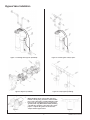 8
8
-
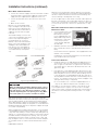 9
9
-
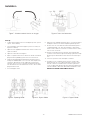 10
10
-
 11
11
-
 12
12
-
 13
13
-
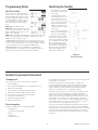 14
14
-
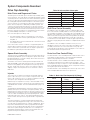 15
15
-
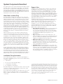 16
16
-
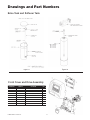 17
17
-
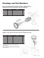 18
18
-
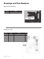 19
19
-
 20
20
-
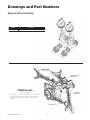 21
21
-
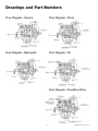 22
22
-
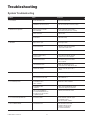 23
23
-
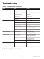 24
24
-
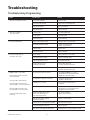 25
25
-
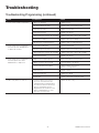 26
26
-
 27
27
-
 28
28


Watts Water Quality And Conditioning PWSR130 Installation guide
- Type
- Installation guide
Ask a question and I''ll find the answer in the document
Finding information in a document is now easier with AI
Other documents
-
 Water Right Sanitizer Plus ASP2-1044 Installation Instructions & Owner's Manual
-
Hellenbrand ProMate DMT Series Owner's manual
-
 Excalibur Water Systems CHLOROSOFT SERIES Installation guide
-
 Proficient H2O Pro315 Next Gen TA HE Alternating Manual
-
 Tahoe T../MA-BTB series Installer Manual
-
Genesis Premier Quick Start Instructions
-
CSI greensand plus IF15-S2 Installation & Operation Manual
-
-
-


