Craftsman 351226061 Owner's manual
- Category
- Power sanders
- Type
- Owner's manual
This manual is also suitable for
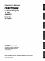
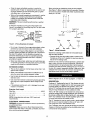
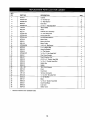
Craftsman 351226061 is a 6 x 48" Oscillating Belt 12" Disc Sander with maximum developed horsepower of 3 and runs at 3450 RPM. It comes with a miter gauge assembly, two handles, and a workstop. The sander can be used for various tasks such as sanding, shaping, and finishing wood, metal, and plastic. The oscillating belt allows for a smoother finish compared to a regular belt sander, and the 12" disc provides a large surface area for sanding. The sander also features a dust hood to help keep the work area clean.
Craftsman 351226061 is a 6 x 48" Oscillating Belt 12" Disc Sander with maximum developed horsepower of 3 and runs at 3450 RPM. It comes with a miter gauge assembly, two handles, and a workstop. The sander can be used for various tasks such as sanding, shaping, and finishing wood, metal, and plastic. The oscillating belt allows for a smoother finish compared to a regular belt sander, and the 12" disc provides a large surface area for sanding. The sander also features a dust hood to help keep the work area clean.


-
 1
1
-
 2
2
-
 3
3
-
 4
4
-
 5
5
-
 6
6
-
 7
7
-
 8
8
-
 9
9
-
 10
10
-
 11
11
-
 12
12
-
 13
13
-
 14
14


Craftsman 351226061 Owner's manual
- Category
- Power sanders
- Type
- Owner's manual
- This manual is also suitable for
Craftsman 351226061 is a 6 x 48" Oscillating Belt 12" Disc Sander with maximum developed horsepower of 3 and runs at 3450 RPM. It comes with a miter gauge assembly, two handles, and a workstop. The sander can be used for various tasks such as sanding, shaping, and finishing wood, metal, and plastic. The oscillating belt allows for a smoother finish compared to a regular belt sander, and the 12" disc provides a large surface area for sanding. The sander also features a dust hood to help keep the work area clean.
Ask a question and I''ll find the answer in the document
Finding information in a document is now easier with AI
Related papers
-
Craftsman 351226060 Owner's manual
-
-
-
-
-
-
-
-
-
Other documents
-
PowerTec BD4600 Owner's manual
-
-
Grizzly G1014Z Owner's manual
-
-
 Grizzly Industrial G1014Z User manual
-
Craftex CX Series CX series Owner's manual
-
Rikon Power Tools 50-114 Operating instructions
-
Grizzly G0864 Owner's manual
-
-
Woodstock Combination Model User manual
