Gigabyte GA-H97-GAMING 3 (REV. 1.0) User manual
- Category
- Motherboards
- Type
- User manual

GA-H97-Gaming 3
User's Manual
Rev. 1001
12ME-H97GM3-1001R

Motherboard
GA-H97-Gaming 3
May 9, 2014
May 9, 2014
Motherboard
GA-H97-Gaming 3

Copyright
© 2014 GIGA-BYTE TECHNOLOGY CO., LTD. All rights reserved.
The trademarks mentioned in this manual are legally registered to their respective owners.
Disclaimer
Information in this manual is protected by copyright laws and is the property of GIGABYTE.
Changes to the specications and features in this manual may be made by GIGABYTE
without prior notice.
No part of this manual may be reproduced, copied, translated, transmitted, or published in any
form or by any means without GIGABYTE's prior written permission.
Documentation Classications
In order to assist in the use of this product, GIGABYTE provides the following types of
documentations:
For detailed product information, carefully read the User's Manual.
For product-related information, check on our website at: http://www.gigabyte.com
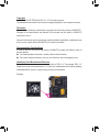
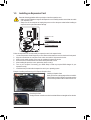
Identifying Your Motherboard Revision
The revision number on your motherboard looks like this: "REV: X.X." For example, "REV: 1.0"
means the revision of the motherboard is 1.0. Check your motherboard revision before updating
motherboard BIOS, drivers, or when looking for technical information.
Example:

- 4 -
Table of Contents
Box Contents ...................................................................................................................6
Optional Items .................................................................................................................6
GA-H97-Gaming 3 Motherboard Layout .........................................................................7
GA-H97-Gaming 3 Motherboard Block Diagram ............................................................8
Chapter 1 Hardware Installation .....................................................................................9
1-1 Installation Precautions ................................................................................... 9
1-2 ProductSpecications ................................................................................... 10
1-3 Installing the CPU and CPU Cooler............................................................... 13
1-3-1 Installing the CPU ..................................................................................................13
1-3-2 Installing the CPU Cooler ......................................................................................15
1-4 Installing the Memory .................................................................................... 16
1-4-1 DualChannelMemoryConguration ....................................................................16
1-4-2 Installing a Memory ................................................................................................17
1-5 Installing an Expansion Card ......................................................................... 18
1-6 Back Panel Connectors ................................................................................. 19
1-7 Internal Connectors ....................................................................................... 21
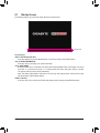
Chapter 2 BIOS Setup .................................................................................................. 31
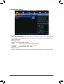
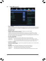
2-1 Startup Screen ............................................................................................... 32
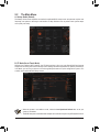
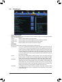
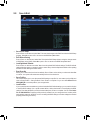
2-2 The Main Menu .............................................................................................. 33
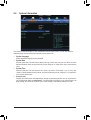
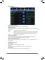
2-3 M.I.T. .............................................................................................................. 36
2-4 System Information ........................................................................................ 47
2-5 BIOS Features ............................................................................................... 48
2-6 Peripherals ..................................................................................................... 52
2-7 Power Management ....................................................................................... 56
2-8 Save & Exit .................................................................................................... 58

- 5 -
Chapter3 ConguringSATAHardDrive(s) ..................................................................59
3-1 ConguringSATAControllers ........................................................................ 59
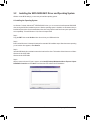
3-2 Installing the SATA RAID/AHCI Driver and Operating System ..................... 71
Chapter 4 Appendix ......................................................................................................75
Drivers Installation .................................................................................................... 75
Regulatory Statements ............................................................................................. 76
Contact Us ................................................................................................................ 79

- 6 -
Optional Items
2-portUSB2.0bracket(PartNo.12CR1-1UB030-6*R)
eSATAbracket(PartNo.12CF1-3SATPW-4*R)
3.5"FrontPanelwith2USB3.0/2.0ports(PartNo.12CR1-FPX582-2*R)
COMportcable(PartNo.12CF1-1CM001-3*R)
HDMI-to-DVIadapter(PartNo.12CT2-HDMI01-1*R)
The box contents above are for reference only and the actual items shall depend on the product package you
obtain. The box contents are subject to change without notice.
Box Contents
5
GA-H97-Gaming 3 motherboard
5
Motherboard driver disk
5
User's Manual
5
Four SATA cables
5
I/O Shield

- 7 -
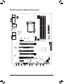
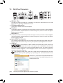
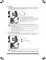
GA-H97-Gaming 3 Motherboard Layout
KB_MS_USB
CPU_FAN
ATX_12V_2X4
ATX
F_AUDIO
B_BIOS
PCIEX4
DDR3_2
DDR3_1
DDR3_4
DDR3_3
BAT
F_PANELCOMA
Intel
®
H97
PCIEX1_2
CLR_CMOS
CODEC
CPU_OPT
M_BIOS
PCI1
PCIEX16
PCIEX1_1
SPDIF_O F_USB2
LGA1150
GA-H97-Gaming 3
DVI
VGA
PCI3
F_USB30
PCI2
SYS_FAN3
SATA3
iTE
®
Super I/O
SYS_FAN2F_USB3 F_USB1TPM
1 0
3 2
SYS_FAN1
M.2
PCIe to
PCI Bridge
SATA_EXPRESS
SATA3
5 4
AUDIO
R_USB30
USB30_LAN
DP_HDMI_SPDIF
Qualcomm
®
Atheros Killer
E2201LAN

- 8 -
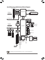
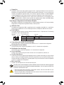
GA-H97-Gaming 3 Motherboard Block Diagram
Fordetailedproductinformation/limitation(s),referto"1-2ProductSpecications."
Dual Channel Memory
PS/2 KB/Mouse
DMI 2.0
FDI
CPUCLK+/-(100MHz)
Dual BIOS
DDR31600/1333MHz
COM
LPC
Bus
Intel
®
H97
iTE
®
Super
I/O
PCIe CLK
(100MHz)
PCIe CLK
(100MHz)
PCI Express Bus
1 PCI Express x16
x1
LAN
RJ45
Intel
®
GbE
LAN
3 PCI
PCI Bus
PCI CLK
(33MHz)
PCIe to PCI
Bridge
x1
PCI Express Bus
x16
D-Sub
4 SATA 6Gb/s
8 USB 2.0/1.1
6 USB 3.0/2.0
Center/Subwoofer Speaker Out
Line Out
MIC
Line In
S/PDIF Out
Side Speaker Out
Rear Speaker Out
CODEC
x1x1
2 PCI Express x1
1 PCI Express x4
Switch
or
x4
SATA Express
M.2
or
or
Switch
2 SATA 6Gb/s
DVI-D
HDMI
DisplayPort
LGA1150 CPU

- 9 -
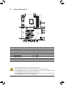
Hardware Installation
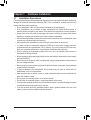
1-1 Installation Precautions
The motherboard contains numerous delicate electronic circuits and components which can become
damagedasaresultofelectrostaticdischarge(ESD).Priortoinstallation,carefullyreadtheuser's
manual and follow these procedures:
• Prior to installation, make sure the chassis is suitable for the motherboard.
• Priortoinstallation,donotremoveorbreak motherboard S/N (Serial Number) sticker or
warranty sticker provided by your dealer. These stickers are required for warranty validation.
• Always remove the AC power by unplugging the power cord from the power outlet before
installing or removing the motherboard or other hardware components.
• Whenconnectinghardwarecomponentstotheinternalconnectorsonthemotherboard,make
sure they are connected tightly and securely.
• Whenhandlingthemotherboard,avoidtouchinganymetalleadsorconnectors.
• Itisbesttowearanelectrostaticdischarge(ESD)wriststrap when handling electronic
components such as a motherboard, CPU or memory. If you do not have an ESD wrist strap,
keepyourhandsdryandrsttouchametalobjecttoeliminatestaticelectricity.
• Prior to installing the motherboard, please have it on top of an antistatic pad or within an
electrostatic shielding container.
• Before unplugging the power supply cable from the motherboard, make sure the power supply
has been turned off.
• Before turning on the power, make sure the power supply voltage has been set according to
the local voltage standard.
• Before using the product, please verify that all cables and power connectors of your hardware
components are connected.
• To prevent damage to the motherboard, do not allow screws to come in contact with the
motherboard circuit or its components.
• Make sure there are no leftover screws or metal components placed on the motherboard or
within the computer casing.
• Do not place the computer system on an uneven surface.
• Do not place the computer system in a high-temperature environment.
• Turning on the computer power during the installation process can lead to damage to system
components as well as physical harm to the user.
• If you are uncertain about any installation steps or have a problem related to the use of the
product,pleaseconsultacertiedcomputertechnician.
Chapter 1 Hardware Installation

- 10 -
Hardware Installation
1-2 ProductSpecications
CPU Support for Intel
®
Core
™
i7 processors/Intel
®
Core
™
i5 processors/
Intel
®
Core
™
i3 processors/Intel
®
Pentium
®
processors/Intel
®
Celeron
®
processors in
theLGA1150package(GotoGIGABYTE'swebsiteforthelatestCPUsupportlist.)
L3 cache varies with CPU
Chipset Intel
®
H97 Express Chipset
Memory 4 x DDR3 DIMM sockets supporting up to 32 GB of system memory
* DuetoaWindows32-bitoperatingsystemlimitation,whenmorethan4GBofphysical
memoryisinstalled,theactualmemorysizedisplayedwillbelessthanthesizeof
the physical memory installed.
Dual channel memory architecture
SupportforDDR31600/1333MHzmemorymodules
Support for non-ECC memory modules
SupportforExtremeMemoryProle(XMP)memorymodules
(GotoGIGABYTE'swebsiteforthelatestsupportedmemoryspeedsandmemory
modules.)
Onboard
Graphics
Integrated Graphics Processor:
- 1xD-Subport,supportingamaximumresolutionof1920x1200@60Hz
- 1xDVI-Dport,supportingamaximumresolutionof1920x1200@60Hz
* TheDVI-DportdoesnotsupportD-Subconnectionbyadapter.
- 1xHDMIport,supportingamaximumresolutionof4096x2160@24Hzor
2560x1600@60Hz
* SupportforHDMI1.4aversion.
- 1xDisplayPort,supportingamaximumresolutionof4096x2160@24Hzor
3840x2160@60Hz
* SupportforDisplayPort1.2version.
- Support for up to 3 displays at the same time
- Maximum shared memory of 1 GB
Audio Realtek
®
ALC1150 codec
SupportforSoundBlasterX-FiMB3
HighDenitionAudio
2/4/5.1/7.1-channel
Support for S/PDIF Out
LAN Qualcomm
®
AtherosKillerE2201LANchip(10/100/1000Mbit)
Expansion Slots 1xPCIExpressx16slot,runningatx16(PCIEX16)
(ThePCIEX16slotconformstoPCIExpress3.0standard.)
* Foroptimumperformance,ifonlyonePCIExpressgraphicscardistobeinstalled,
besuretoinstallitinthePCIEX16slot.
1xPCIExpressx16slot,runningatx4(PCIEX4)
* ThePCIEX4slotsharesbandwidthwiththePCIExpressx1slots.ThePCIExpress
x1 slots will become unavailable when a PCIe x4 expansion card is installed.
* Wheninstalling ax8 orabove cardinthe PCIEX4slot, makesure toset PCIE
SlotConguration(PCH)inBIOSSetuptox4.(RefertoChapter2,"BIOSSetup,"
"Peripherals,"formoreinformation.)
2 x PCI Express x1 slots
(ThePCIEX4andthePCIExpressx1slotsconformtoPCIExpress2.0standard.)
3 x PCI slots

- 11 -
Hardware Installation
Multi-Graphics
Technology
Supportfor2-WayAMDCrossFire
™
technology
Storage Interface Chipset:
- 1 x M.2 PCIe connector
- 1 x SATA Express connector
- 6 x SATA 6Gb/s connectors
(M.2,SATAExpress,andSATA34/5connectorscanonlybeusedoneatatime.
TheSATA34/5connectorswillbecomeunavailablewhenanM.2SSDisinstalled.)
- Support for RAID 0, RAID 1, RAID 5, and RAID 10
USB Chipset:
- 6xUSB3.0/2.0ports(4portsonthebackpanel,2portsavailablethrough
theinternalUSBheader)
- 8xUSB2.0/1.1ports(2portsonthebackpanel,6portsavailablethrough
theinternalUSBheaders)
Internal
Connectors
1x24-pinATXmainpowerconnector
1x8-pinATX12Vpowerconnector
1 x M.2 PCIe connector
1 x SATA Express connector
6 x SATA 6Gb/s connectors
1 x USB 3.0/2.0 header
3 x USB 2.0/1.1 headers
1 x CPU fan header
1xwatercoolingfanheader(CPU_OPT)
3 x system fan headers
1 x front panel header
1 x front panel audio header
1 x serial port header
1xTrustedPlatformModule(TPM)header
1 x S/PDIF Out header
1 x Clear CMOS jumper
Back Panel
Connectors
1 x PS/2 keyboard/mouse port
1 x D-Sub port
1 x DVI-D port
1 x HDMI port
1 x DisplayPort
4 x USB 3.0/2.0 ports
2 x USB 2.0/1.1 ports
1 x RJ-45 port
6xaudiojacks(Center/SubwooferSpeakerOut,RearSpeakerOut,SideSpeaker
Out,LineIn,LineOut,MicIn)
I/O Controller iTE
®
I/O Controller Chip

- 12 -
Hardware Installation
Hardware
Monitor
System voltage detection
CPU/System temperature detection
CPU/CPU OPT/System fan speed detection
CPU/System overheating warning
CPU/CPU OPT/System fan fail warning
CPU/CPU OPT/System fan speed control
* Whetherthefanspeedcontrolfunctionissupportedwilldependonthecooleryou
install.
BIOS 2x64Mbitash
Use of licensed AMI UEFI BIOS
Support for DualBIOS
™
PnP 1.0a, DMI 2.7, WfM 2.0, SM BIOS 2.7, ACPI 5.0
Unique Features Support for APP Center
* AvailableapplicationsinAPPCentermaydifferbymotherboardmodel.Supported
functions of each application may also differ depending on motherboard
specications.
- @BIOS
- EasyTune
- EZ Setup
- Fast Boot
- Game Controller
- ON/OFFCharge
- Smart TimeLock
- Smart Recovery2
- System Information Viewer
- USB Blocker
Support for Q-Flash
Support for Smart Switch
SupportforXpressInstall
Bundled
Software
Norton
®
InternetSecurity(OEMversion)
Intel
®
Rapid Start Technology
Intel
®
Smart Connect Technology
Intel
®
Smart Response Technology
Operating
System
SupportforWindows8.1/8/7
Form Factor ATXFormFactor;30.5cmx21.4cm
* GIGABYTEreservestherighttomakeanychangestotheproductspecicationsandproduct-relatedinformationwithout
prior notice.
* PleasevisittheSupport&Downloads\UtilitypageonGIGABYTE'swebsitetocheckthesupportedoperatingsystem(s)for
the software listed in the "Unique Features" and "Bundled Software" columns.

- 13 -
Hardware Installation
1-3 Installing the CPU and CPU Cooler
Read the following guidelines before you begin to install the CPU:
• Make sure that the motherboard supports the CPU.
(GotoGIGABYTE'swebsiteforthelatestCPUsupportlist.)
• Always turn off the computer and unplug the power cord from the power outlet before installing the
CPU to prevent hardware damage.
• LocatethepinoneoftheCPU.TheCPUcannotbeinsertediforientedincorrectly.(Oryoumaylocate
thenotchesonbothsidesoftheCPUandalignmentkeysontheCPUsocket.)
• Apply an even and thin layer of thermal grease on the surface of the CPU.
• Do not turn on the computer if the CPU cooler is not installed, otherwise overheating and damage
of the CPU may occur.
• SettheCPUhostfrequencyinaccordancewiththe CPUspecications. Itis notrecommended
thatthesystembusfrequencybesetbeyondhardwarespecicationssinceitdoesnotmeetthe
standard requirements for the peripherals. If you wish to set the frequency beyond the standard
specications,pleasedosoaccordingtoyourhardwarespecicationsincludingtheCPU,graphics
card, memory, hard drive, etc.
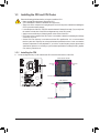
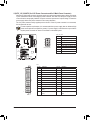
1-3-1 Installing the CPU
A. Locate the alignment keys on the motherboard CPU socket and the notches on the CPU.
Notch
Alignment
Key
Alignment
Key
Notch
LGA1150 CPU
LGA1150 CPU Socket
Pin One Corner of the CPU Socket
Triangle Pin One Marking on the CPU

- 14 -
Hardware Installation
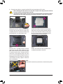
B. Follow the steps below to correctly install the CPU into the motherboard CPU socket.
Step 1:
Gently press the CPU socket lever handle down
andawayfromthesocketwithyournger.Then
completely lift the CPU socket lever and the metal
load plate/plastic cover will be lifted as well.
Step 2:
HoldtheCPUwithyourthumbandindexngers.
AligntheCPUpinonemarking(triangle)withthe
pinonecorneroftheCPUsocket(oryoumayalign
theCPUnotcheswiththesocketalignmentkeys)
and gently insert the CPU into position.
Step 4:
Finally, secure the lever under its retention tab to
complete the installation of the CPU.
NOTE:
Hold the CPU socket lever by the handle, not the lever base portion.
• Before installing the CPU, make sure to turn off the computer and unplug the power cord from
the power outlet to prevent damage to the CPU.
• To protect the socket contacts, do not remove the protective plastic cover unless the CPU is
inserted into the CPU socket. Save the cover properly and replace it if the CPU is removed.
Step 3:
Once the CPU is properly inserted, carefully
replacetheloadplate.Whenreplacingtheload
plate, make sure the front end of the load plate
is under the shoulder screw. Then press the CPU
socket lever. The protective plastic cover may
pop off from the load plate during the process of
engagingthelever.Removethecover.(Savethe
cover properly and always replace it when the
CPUisnotinstalled.)

- 15 -
Hardware Installation
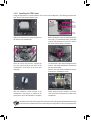
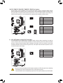
1-3-2 Installing the CPU Cooler
FollowthestepsbelowtocorrectlyinstalltheCPUcooleronthemotherboard.(Thefollowingprocedureuses
Intel
®
boxedcoolerastheexamplecooler.)
Use extreme care when removing the CPU cooler because the thermal grease/tape between the CPU
cooler and CPU may adhere to the CPU. Inadequately removing the CPU cooler may damage the CPU.
Step 5:
After the installation, check the back of the
motherboard. If the push pin is inserted as the
picture above shows, the installation is complete.
Step 6:
Finally, attach the power connector of the CPU
coolertotheCPUfanheader(CPU_FAN)onthe
motherboard.
Step 1:
Apply an even and thin layer of thermal grease on
the surface of the installed CPU.
Step 2:
Before installing the cooler, note the direction of the
arrow sign onthemalepushpin.(Turningthe
push pin along the direction of arrow is to remove
thecooler,onthecontrary,istoinstall.)
Step 3:
Place the cooler atop the CPU, aligning the
four push pins through the pin holes on the
motherboard. Push down on the push pins
diagonally.
Step 4:
You should hear a "click" when pushing down each
push pin. Check that the Male and Female push
pins are joined closely.
(RefertoyourCPUcoolerinstallationmanualfor
instructionsoninstallingthecooler.)
Male
Push Pin
Female
Push Pin
The Top
of Female
Push Pin
Direction of
the Arrow Sign
on the Male
Push Pin

- 16 -
Hardware Installation
1-4 Installing the Memory
Read the following guidelines before you begin to install the memory:
• Make sure that the motherboard supports the memory. It is recommended that memory of the same
capacity, brand, speed, and chips be used.
(GotoGIGABYTE'swebsiteforthelatestsupportedmemoryspeedsandmemorymodules.)
• Always turn off the computer and unplug the power cord from the power outlet before installing the
memory to prevent hardware damage.
• Memory modules have a foolproof design. A memory module can be installed in only one direction.
If you are unable to insert the memory, switch the direction.
DualChannelMemoryCongurationsTable:
(SS=Single-Sided,DS=Double-Sided,"--"=NoMemory)
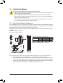
1-4-1 DualChannelMemoryConguration
This motherboard provides four DDR3 memory sockets and supports Dual Channel Technology. After the
memoryisinstalled,theBIOSwillautomaticallydetectthespecicationsandcapacityofthememory.Enabling
Dual Channel memory mode will double the original memory bandwidth.
The four DDR3 memory sockets are divided into two channels and each channel has two memory sockets as
following:
Channel A: DDR3_2, DDR3_4
Channel B: DDR3_1, DDR3_3
DDR3_4
DDR3_2
DDR3_3
DDR3_1
Due to CPU limitations, read the following guidelines before installing the memory in Dual Channel mode.
1. Dual Channel mode cannot be enabled if only one DDR3 memory module is installed.
2. WhenenablingDualChannelmodewithtwoorfourmemorymodules,itisrecommendedthatmemory
of the same capacity, brand, speed, and chips be used and installed in the same colored DDR3
sockets. For optimum performance, when enabling Dual Channel mode with two memory modules,
we recommend that you install them in the DDR3_1 and DDR3_2 sockets.
DDR3_4 DDR3_2 DDR3_3 DDR3_1
Two Modules
- - DS/SS - - DS/SS
DS/SS - - DS/SS - -
Four Modules DS/SS DS/SS DS/SS DS/SS

- 17 -
Hardware Installation
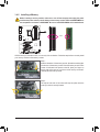
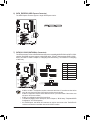
1-4-2 Installing a Memory
Before installing a memory module, make sure to turn off the computer and unplug the power
cord from the power outlet to prevent damage to the memory module. DDR3 and DDR2 DIMMs are
not compatible to each other or DDR DIMMs. Be sure to install DDR3 DIMMs on this motherboard.
Notch
DDR3 DIMM
ADDR3memorymodulehasanotch,soitcanonlytinonedirection.Followthestepsbelowtocorrectlyinstall
your memory modules in the memory sockets.
Step 1:
Notetheorientationofthememorymodule.Spreadtheretainingclips
at both ends of the memory socket. Place the memory module on the
socket.Asindicatedinthepictureontheleft,placeyourngerson
the top edge of the memory, push down on the memory and insert it
vertically into the memory socket.
Step 2:
The clips at both ends of the socket will snap into place when the
memory module is securely inserted.

- 18 -
Hardware Installation
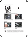
1-5 Installing an Expansion Card
Read the following guidelines before you begin to install an expansion card:
• Make sure the motherboard supports the expansion card. Carefully read the manual that came with
your expansion card.
• Always turn off the computer and unplug the power cord from the power outlet before installing an
expansion card to prevent hardware damage.
PCI Express x1 Slot
PCI Express x16 Slot
PCI Slot
Follow the steps below to correctly install your expansion card in the expansion slot.
1. Locate an expansion slot that supports your card. Remove the metal slot cover from the chassis back panel.
2. Align the card with the slot, and press down on the card until it is fully seated in the slot.
3. Make sure the metal contacts on the card are completely inserted into the slot.
4. Secure the card's metal bracket to the chassis back panel with a screw.
5. Afterinstallingallexpansioncards,replacethechassiscover(s).
6. Turn on your computer. If necessary, go to BIOS Setup to make any required BIOS changes for your
expansioncard(s).
7. Install the driver provided with the expansion card in your operating system.
Example: Installing and Removing a PCI Express Graphics Card:
• Installing a Graphics Card:
Gently push down on the top edge of the card until it is
fully inserted into the PCI Express slot. Make sure the
card is securely seated in the slot and does not rock.
• Removing the Card:
Gently push back on the lever on the slot and then lift the card straight out from the slot.

- 19 -
Hardware Installation
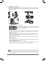
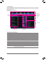
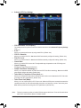
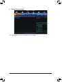
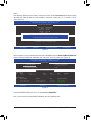
1-6 Back Panel Connectors
USB 2.0/1.1 Port
TheUSBportsupportsthe USB2.0/1.1 specication.Usethisportfor USBdevices suchas aUSB
keyboard/mouse,USBprinter,USBashdriveandetc.
PS/2 Keyboard/Mouse Port
Use this port to connect a PS/2 mouse or keyboard.
D-Sub Port
TheD-Subportsupportsa15-pinD-Subconnectorandsupportsamaximumresolutionof1920x1200@60Hz
(theactualresolutionssupporteddependonthemonitorbeingused).Connectamonitorthatsupports
D-Sub connection to this port.
DVI-D Port
(Note)
TheDVI-DportconformstotheDVI-Dspecicationandsupportsamaximumresolutionof1920x1200@60Hz
(theactualresolutionssupporteddependonthemonitorbeingused).Connectamonitorthatsupports
DVI-D connection to this port.
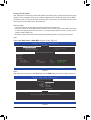
Optical S/PDIF Out Connector
This connector provides digital audio out to an external audio system that supports digital optical audio.
Before using this feature, ensure that your audio system provides an optical digital audio in connector.
HDMI Port
The HDMI port is HDCP compliant and supports Dolby True HD and DTS HD
MasterAudio formats.It alsosupports upto 192KHz/24bit8-channel LPCM
audio output. You can use this port to connect your HDMI-supported monitor. The maximum supported
resolutionis4096x2160@24Hzor2560x1600@60Hz,buttheactualresolutionssupportedare
dependent on the monitor being used.
After installing the HDMI device, make sure to set the default sound playback device to HDMI.
(Theitemnamemaydifferdependingonyouroperatingsystem.Thescreenshotbelowisfrom
Windows8.1.)
InWindows8.1,selectApps>ControlPanel>Hardwareand
Sound>Sound>Playback,setIntel(R)DisplayAudiotothe
default playback device.
(Note) TheDVI-DportdoesnotsupportD-Subconnectionbyadapter.

- 20 -
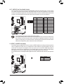
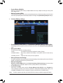
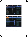
Hardware Installation
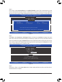
Center/Subwoofer Speaker Out Jack (Orange)
Usethisaudiojacktoconnectcenter/subwooferspeakersina5.1/7.1-channelaudioconguration.
Rear Speaker Out Jack (Black)
Thisjackcanbeusedtoconnectfrontspeakersina4/5.1/7.1-channelaudioconguration.
Side Speaker Out Jack (Gray)
Usethisaudiojacktoconnectsidespeakersina7.1-channelaudioconguration.
Line In Jack (Blue)
The line in jack. Use this audio jack for line in devices such as an optical drive, walkman, etc.
Line Out Jack (Green)
The line out jack. This jack supports audio amplifying function. For better sound quality, it is recom-mended
thatyouconnectyourheadphone/speakertothisjack(actualeffectsmayvarybythedevicebeingused).
Use this audio jack for a headphone or 2-channel speaker. This jack can be used to connect front speakers
ina4/5.1/7.1-channelaudioconguration.
Mic In Jack (Pink)
The Mic in jack. Microphones must be connected to this jack.
USB 3.0/2.0 Port
TheUSB3.0portsupportstheUSB3.0specicationandiscompatibletotheUSB2.0/1.1specication.
UsethisportforUSBdevicessuchasaUSBkeyboard/mouse,USBprinter,USBashdriveandetc.
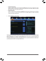
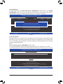
RJ-45 LAN Port
TheGigabit EthernetLAN portprovidesInternetconnectionatupto1Gbps datarate.Thefollowing
describesthestatesoftheLANportLEDs.
Theaudiojackscanbereconguredtoperformdifferentfunctionsviatheaudiosoftware(supported
functionsforeachjackmayvarybasedonhardwarespecication). Only microphones still MUST be
connected to the default Mic in jack.
Triple-DisplayCongurationsfortheOnboardGraphics:
Triple-displaycongurationsaresupportedafteryouinstallmotherboarddriversinOS.Onlydual-display
congurationsaresupportedduringtheBIOSSetuporPOSTprocess.
• Whenremovingthecableconnectedtoabackpanelconnector,rstremovethecablefromyour
device and then remove it from the motherboard.
• Whenremovingthecable,pullitstraightoutfromtheconnector.Donotrockitsidetosidetoprevent
an electrical short inside the cable connector.
DisplayPort
DisplayPort delivers high quality digital imaging and audio, supporting bi-directional audio transmission.
DisplayPort can support both DPCP and HDCP content protection mechanisms. You can use this port to
connectyourDisplayPort-supportedmonitor.Themaximumsupportedresolutionis4096x2160@24Hz
or3840x2160@60Hz,buttheactualresolutionssupportedaredependentonthemonitorbeingused.
After installing the DisplayPort device, make sure the default device for sound playback is the
DisplayPortdevice.(Theitemnamemaydifferfromoperatingsystem.RefertotheHDMIsettings
informationonthepreviouspageforthecongurationdialogbox.)
Activity LED
Connection/
Speed LED
LANPort
Activity LED:Connection/Speed LED:
State Description
Orange 1 Gbps data rate
Green 100 Mbps data rate
Off 10 Mbps data rate
State Description
Blinking Data transmission or receiving is occurring
Off Nodatatransmissionorreceivingisoccurring
Page is loading ...
Page is loading ...
Page is loading ...
Page is loading ...
Page is loading ...
Page is loading ...
Page is loading ...
Page is loading ...
Page is loading ...
Page is loading ...
Page is loading ...
Page is loading ...
Page is loading ...
Page is loading ...
Page is loading ...
Page is loading ...
Page is loading ...
Page is loading ...
Page is loading ...
Page is loading ...
Page is loading ...
Page is loading ...
Page is loading ...
Page is loading ...
Page is loading ...
Page is loading ...
Page is loading ...
Page is loading ...
Page is loading ...
Page is loading ...
Page is loading ...
Page is loading ...
Page is loading ...
Page is loading ...
Page is loading ...
Page is loading ...
Page is loading ...
Page is loading ...
Page is loading ...
Page is loading ...
Page is loading ...
Page is loading ...
Page is loading ...
Page is loading ...
Page is loading ...
Page is loading ...
Page is loading ...
Page is loading ...
Page is loading ...
Page is loading ...
Page is loading ...
Page is loading ...
Page is loading ...
Page is loading ...
Page is loading ...
Page is loading ...
Page is loading ...
Page is loading ...
Page is loading ...
Page is loading ...
-
 1
1
-
 2
2
-
 3
3
-
 4
4
-
 5
5
-
 6
6
-
 7
7
-
 8
8
-
 9
9
-
 10
10
-
 11
11
-
 12
12
-
 13
13
-
 14
14
-
 15
15
-
 16
16
-
 17
17
-
 18
18
-
 19
19
-
 20
20
-
 21
21
-
 22
22
-
 23
23
-
 24
24
-
 25
25
-
 26
26
-
 27
27
-
 28
28
-
 29
29
-
 30
30
-
 31
31
-
 32
32
-
 33
33
-
 34
34
-
 35
35
-
 36
36
-
 37
37
-
 38
38
-
 39
39
-
 40
40
-
 41
41
-
 42
42
-
 43
43
-
 44
44
-
 45
45
-
 46
46
-
 47
47
-
 48
48
-
 49
49
-
 50
50
-
 51
51
-
 52
52
-
 53
53
-
 54
54
-
 55
55
-
 56
56
-
 57
57
-
 58
58
-
 59
59
-
 60
60
-
 61
61
-
 62
62
-
 63
63
-
 64
64
-
 65
65
-
 66
66
-
 67
67
-
 68
68
-
 69
69
-
 70
70
-
 71
71
-
 72
72
-
 73
73
-
 74
74
-
 75
75
-
 76
76
-
 77
77
-
 78
78
-
 79
79
-
 80
80


Gigabyte GA-H97-GAMING 3 (REV. 1.0) User manual
- Category
- Motherboards
- Type
- User manual
Ask a question and I''ll find the answer in the document
Finding information in a document is now easier with AI
Related papers
-
Gigabyte GA-Z77P-D3 User manual
-
-
Gigabyte GA-H97-D3H User manual
-
Gigabyte GA-Z97-HD3 User manual
-
Gigabyte GA-Z270X-Gaming 5 Installation guide
-
Gigabyte G1.Sniper Z5 User manual
-
-
Gigabyte GA-H87N-WIFI Owner's manual
-
Gigabyte B365M GAMING HD Owner's manual
-
Other documents
-
ASRock Rack H97M WS Installation guide
-
ASROCK Z370 EXTREME4 Installation guide
-
Ewent EW9172 Datasheet
-
ASROCK C226 WS Quick start guide
-
SIIG LB-US0414-S1 Installation guide
-
ECS Q87H3-M6 User manual
-
Giada PC68 User manual
-
ECS B85H3-M User manual
-
Asus Z87-PRO User manual
-
BCM Advanced Research MX310H Installation guide