Page is loading ...

Manual # P80151147B - Date:2017/07/28
Failure to comply with these instructions could
result in a fire or explosion that could cause
serious bodily injury, death or property damage.
Whether this grill was assembled by you or
someone else, you must read this entire manual
before using your grill to ensure the grill is
properly assembled, installed and maintained.
Use your grill at least 3 feet away from any
wall or surface. Use your grill at least 3 feet
away from combustible objects that can melt or
catch fire such as vinyl or wood siding, fences
and overhangs or sources of ignition including
pilot lights on water heaters and live electrical
appliances.
THIS GAS APPLIANCE IS DESIGNED FOR
OUTDOOR USE ONLY.
Never use your gas grill in a garage, porch,
shed, breezeway or any other enclosed area.
Never obstruct the flow of ventilation air
around your gas grill housing.
Never disconnect the gas regulator or any gas
fitting while your grill is lit. A lit grill can ignite
leaking gas and cause a fire or explosion which
could result in property damage, personal injury
or death.
Ÿ
Ÿ
Ÿ
Ÿ
Ÿ
Ÿ
WARNING
! !
Ÿ
Grill Information Center:
Ÿ
Ÿ
NOTE TO ASSEMBLER / INSTALLER:
Leave this manual with the consumer.
NOTE TO CONSUMER:
Keep this manual for future reference.
RECORD YOUR SERIAL #
__________________
(see silver CSA label on main body of grill)
IMPORTANT:
Ÿ
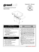
FREE HELP
FROM THE GRILL EXPERTS
Barbeques Galore is the expert on this
product and trained to help you with:
visit www.grandhall.com or call:
1-800-474-5587
Monday - Friday 8:00am-4:30pm PST
Assembly Questions
Grill Operation
Replacement of Damaged or Missing parts
Ÿ
Ÿ
Ÿ
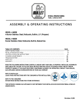
Liquid Propane Gas (LPG) Grill
Models BTE2616(A,B)LP, BTE3216(A,B)LP & BTE3816BLP
Natural Gas (NG ) Grill
Models BTE2616(A,B)NG, BTE3216(A,B)NG & BTE3816BNG
BTE3216BLP/NG
BTE3816BLP/NG
Operator's Manual
BTE3216ALP/NGBTE2616ALP/NG
BTE2616BLP/NG
(BTE2616B+UN2616ACT)
(BTE3216B+UN3216ACT)

Table of Contents
Primary Safety Warnings............................1-3
Pre-Assembly Instructions...............................3
Part Diagrams and Lists............................5-13
Assembly Instructions.................................15-18
Use & Care Instructions:
• Gas Safety and Leak Tests..............19-21
• Natural Gas Connection............................22
• Lighting Instructions and Light Operation.23
• Troubleshooting...........................................24
• Rotisserie Instruction..............................25-27
Cleaning and Maintenance........................28-29
Cooking Guide............................................A1-A4
Frequently Asked Questions...................A5-A6
Warranty...........................................Back Cover
2
Do not store or use gasoline or other
flammable liquids or vapors in the
vicinity of this or any other
appliances.
An LP cylinder not connected for
use shall not be stored in the vicinity
of this or any other appliance.
1.
2.
•
LPG models must be used with Liquid Propane
Gas and the regulator assembly supplied. Natural
Gas models must be used with Natural Gas only.
Any attempt to convert the grill from one fuel type
to another is extremely hazardous and will void the
warranty.
Keep gas regulator hose away from hot grill sur-
faces and dripping grease. Avoid unnecessary twist-
ing of hose. Visually inspect hose prior to each use
for cuts, cracks, excessive wear or other damage.
If the hose appears damaged do not use the gas
grill. Call 1-800-474-5587 for a certified replace-
ment hose.
California Proposition 65
Combustion byproducts produced when using this
product contain chemicals known to the State of Cali-
fornia to cause cancer, birth defects, or other reproduc-
tive harm.
Brass components on the grill, such as hose fittings,
propane cylinder valves (sold separately) and burner
valve stems, contain lead which is known to the State
of California to cause cancer, birth defects, or other
reproductive harm.
Never use charcoal or lighter fluid in this gas grill.
Failure to comply with these instructions could result
in a grease fire or explosion that could cause serious
bodily injury, death or property damage.
Before each use of your grill: Inspect the Grease Tray,
Grease Tray Heat Shield and inside of the Grill Bowl to
be sure there is no excessive grease and debris
buildup. Clean the Grease Tray, Grease Tray Heat
Shield and inside of the Grill Bowl frequently to elimi-
nate grease/debris build-up and to prevent grease
fires. Failure to comply with these instructions could
result in a grease fire and even a subsequent explo-
sion that could cause serious bodily injury, death or
property damage.
•
•
•
•
!
This appliance, when installed, must be electri-
cally grounded in accordance with local codes
or, in the absence of local codes, with the
National Electrical Code, ANSI/NFPA 70, or the
Canadian Electrical Code, CSA C22.1.
Keep any electrical supply cord and the fuel
supply hose away from any heated surfaces.
•
•
WARNING
!
DANGER
!
!
1.
2.
3.
4.
If you smell gas:
Shut off gas to the appliance.
Extinguish any open flame.
Open lid.
If odor continues, keep away from
the appliance and immediately call
your gas supplier or your fire
department.
WARNING
! !
WARNING
! !
CSA label located on
the bowl rear panel.
Never cover or wrap the Cooking Grids, bottom of
the Grill Bowl, Grease Tray with aluminum foil or
any other material that will absorb grease.
! !
WARNING

Pre-Assembly Instructions For Your Safety
WARNING
CAUTION
! !
Failure to comply with these instructions may result
in a hazardous situation which, if not avoided, may
result in injury.
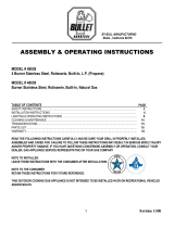
METHOD 1: Bend a stiff wire or wire coat hanger
into a small hook as shown and run the hook
through the Burner Tube and inside the Burner
several times to remove debris.
METHOD 2: Use a bottle brush with a flexible
handle and run the brush through the Burner
Tube and inside the Burner several times to
remove any debris.
METHOD 3: Use an air hose to force air through
each Burner Tube. The forced air should pass
debris or obstructions through the Burner and out
the Ports.
TO CLEAN BURNER TUBE,
INSERT HOOK
HERE
Burner Tube
9
3
Burner Port
Foot
1.
2.
3.
4.
Refer to the figure below and perform one of these
3 cleaning methods:
Carefully lift each Burner up and away from the Gas
Valve Orifice.
Check and clean Burner/Venturi Tubes for insects
and insect nests. A clogged tube can lead to a fire
beneath the grill.
Spiders and small insects can spin webs and nest
in the grill Burner Tubes during transit and ware-
housing which can lead to a gas flow obstruction
resulting in a fire in and around the Burner Tubes.
This type of "FLASHBACK FIRE" can cause serious
grill damage and create an unsafe operating con-
dition for the user.
To reduce the chance of FLASHBACK FIRE
you must clean the Burner Tubes as follows
before initial use. Also do this at least once a
month in summer and fall or whenever spiders are
active in your area, and if your grill has not been
used for an extended period of time.
Remove the screws from the rear of each Main Burner
using a Phillips head screwdriver or wrench.
WARNING: Grease can get very hot. Always handle the Grease
Tray with a flame retardant BBQ mitt. Before removing the
Tray, always be sure that the grill has properly cooled. Be
aware that the Tray does contain grease and be extremely
careful when removing the Tray to prevent spillage. Failure to
follow these instructions could cause serious bodily injury or
property damage.
Grill Installation Codes
The installation must conform with local codes or, in the
absence of local codes, with either the National Fuel Gas
Code, ANSI Z223.1/NFPA 54, Natural Gas and Propane
Installation Code, CSA B149.1, or Propane Storage and
Handling Code, B149.2.
•
•
•
PRE-ASSEMBLY
Read and perform the following pre-assembly instruc-
tions:
Tools Required for Assembly:
protective work gloves
protective eyewear
You will need assistance from another person to handle
the grill head and other large, heavy parts.
Open lid of shipping carton. Remove top sheet of
cardboard and packing materials. Lay cardboard sheet
on floor and use as a work surface to protect floor and
grill parts from scratches.
You may slice the carton front corners with a utility knife
to lay open the carton front panel. This allows you to
raise the Lid and remove the components packed inside,
making it easier to lift.
Use the Hardware and Part Diagrams to ensure all items
are included and free of damage.
Do not throw away the bags of hardware that are in-
cluded with boxed parts. These are required for assem-
bly.
Do not assemble or operate the grill if it appears
damaged. If there are damaged or missing parts when
you unpack the shipping box or you have questions dur-
ing the assembly process call 1-800-474-5587 M-F 8AM-
4:30PM PST for assistance.
CAUTION
!
When using electrical appliances, basic safety
precautions should always be used.
!
Phillips head screwdriver

4
*One AA Battery included in the Hardware Pack
Hardware Diagram for Models BTE2616BLP/NG & BTE3216BLP/NG & BTE3816BLP/NG
Hardware Parts List for Models BTE2616BLP/NG & BTE3216BLP/NG & BTE3816BLP/NG
Pan Head Screw 3/16"x3/8"
Part # S182G03061
Qty. 7 (For Models BTE2616BLP,BTE3216BLP, BTE3816BLP)
Qty. 2 (For Models BTE2616BNG, BTE3216BNG & BTE3816BNG)
PART # PART DESCRIPTION QTY PURPOSE OF PART
P06013018CHardware Pack 1 For use in assembly of Models BTE2616B, BTE3216B, BTE3816B
S182G03061Pan Head Screw 3/16" x 3/8" 2 Install the Transformer Bracket (BTE2616B, BTE3216B, BTE3816B)
S182G03061Pan Head Screw 3/16" x 3/8" 2 Install the Bracket with LP Regulator (LPG Model Only)
S182G03061Pan Head Screw 3/16" x 3/8" 3 Install the Tank Tray Set onto the Bottom Panel (LPG Model Only)
S313G0306BAA Battery 1

Parts Diagram for Models BTE2616BLP & BTE2616BNG
5
1
2a
3
5
6
13
15
4
7
8
6
9
9
32
27
20
16
18
28
17
26
14
14
10
10
11
12
19
21
22
23
24
25
31
29
30
41
46
47
50
40
44
39
38
43
42
48
49
45
37
35
36
34
33
37
53
52
55
51
54
2b
58
56
57

Parts List for Models BTE2616BLP & BTE2616BNG
6
KEY DESCRIPTION PART#
QTY.
1 Lid Assembly P0014644AA
1
2a Temperature Gauge P00601551A
1
2b Temperature Gauge Seat P00614031A
1
3 Lid Handle Bracket, Left P00307052E
1
4 Lid Handle Bracket, Right P00308052E
1
5 Lid Handle P00215041H
1
6 Protective Pad P05518002I
4
7 Lid Assembly Bracket, Left P03320007C
1
8 Lid Assembly Bracket, Right P03320008C
1
9 Lid Hinge with Nut P05501136L
2
10 Lid Trim Plate Bracket P03318007A
2
11 Lid Assembly Reinforcing Bracket, Left P033180084
1
12 Lid Assembly Reinforcing Bracket, Right P033180094
1
13 Lid Trim Plate P0011464A4
1
14 Warming Rack Bracket P01529002J
2
15 Warming Rack P01514023B
1
16 Cooking Grid P016060404
2
17 Flame Tamer with Ceramic P01720041A
3
18 Burner/Main P02001070B
3
Back Burner Cover (LPG) P06906107C
1
Back Burner Cover (NG) P06906108C
1
20 Trim Panel, Rear P07515030A
1
21
Bowl Side Panel, Rear/Upper
P0075822BC
1
22 Back Burner Thermocouple Protector P03328050C 1
23 Thermocouple for Back Burner P05305072B 1
24 Back Burner Electrode P02614071C 1
Back Burner Assembly (LPG) Y0030028
1
Back Burner Assembly (NG) Y0030029
1
26 Back Burner Extension Tube P03701011A 1
27 Bowl Side Panel, Rear/Lower P0073756FC 1
28 Burner Bracket P02208047A 1
29 Bowl Rear Panel Assembly P0077201B4 1
30 Bowl Front Panel P0076315BC 1
31 Bowl Side Panel, Left P007613564 1
32 Bowl Side Panel, Right P007623464 1
33 Bowl Side Trim Plate, Left / Upper P0077301R4 1
34 Bowl Side Trim Plate, Right / Upper P0077401R4 1
35 Bowl Side Trim Plate, Left / Lower P0077501R4 1
36 Bowl Side Trim Plate, Right / Lower P0077601R4 1
37 Grease Shield P069021414 2
38 Electric Wires Set P02615203A 1
39 Gas Collector Box with Electrode P02608061A 2
19
25

Parts List for Models BTE2616BLP & BTE2616BNG
7
KEY
DESCRIPTION PART#
QTY.
Gas Valve/Manifold Assembly (LPG) Y0060840
1
Gas Valve/Manifold Assembly (NG) Y0060841
1
41 Bowl Front Trim Plate Assembly P02917011S 1
42 Electric Wires Set P02627024A 1
43 LED Rectifier with Wire Assembly P05383020B 1
44 Control Panel P02917043S
1
45 Switch for Light P05360004B 1
46 Control Knob Seat with LED light P03445014A
3
47 Control Knob for Main Burner P03446024A 3
48 LED Light for Back Burner P05373011B
1
49 Control Knob for Back Burner P03418245U 1
50 Electric Ignitor - 4 Ports P02505014G 1
51 Grease Tray Heat Shield P06904064C
1
52 Grease Tray Handle P0272017CC
1
53 Grease Tray P02717923C
1
54 Grease Tray Slide Set P05516140M
1
55 Lighting Stick P05507140M
1
56 Transformer Bracket P03328057A
1
57 Transformer Wire Set P05352027B
1
58 Transformer P05374021B
1
59 Regulator Hose Connector (LPG) P03901056C
1
60 Regulator with Hose(LPG) P03635005A
1
61 Regulator with Connector (NG) P03614005C 1
62 Tank Tray Set (LPG) Y0340055
1
Rotisserie Assembly Y0250219 1
Hardware Pack P06013018C 1
Operator's Manual P80151147B 1
40

Parts Diagram for Models BTE3216BLP & BTE3216BNG
8
16
18
36
13
29
30
32
33
34
41a
41b
63
62
64
19
20
21
23
24
25
2b
43
52
26
27
46
31
42
51
65
48
53
21
20
55
28
17
3
2a
5
45
4
58
50
49
47
44
54
1
56
57
35
15
22
6
7
8
6
9
9
14
14
10
10
11
12
40
39
38
37
40
61
59
60

Parts List for Models BTE3216BLP & BTE3216BNG
9
KEY
DESCRIPTION PART#
QTY.
1 Lid Assembly P0014759AA 1
2a Temperature Gauge P00601551A 1
2b Temperature Gauge Seat P00614031A 1
3 Lid Handle Bracket, Left P00307052E 1
4 Lid Handle Bracket, Right P00308052E 1
5 Lid Handle P00215039H 1
6 Protective Pad P05518002I 4
7 Lid Assembly Bracket, Left P03320007C 1
8 Lid Assembly Bracket, Right P03320008C 1
9 Lid Hinge with Nut P05501136L 2
10 Lid Trim Plate Bracket P03318007A 2
11 Lid Assembly Reinforcing Bracket, Left P003180084 1
12 Lid Assembly Reinforcing Bracket, Right P033180094 1
13 Lid Trim Plate P0011465A4 1
14 Warming Rack Bracket P01529002J 2
15 Warming Rack P01515032B 1
16 Cooking Grid P01606041B 4
17 Flame Tamer with Ceramic P01720041A 4
18 Burner/Main P02001070B
4
Back Burner Cover(LPG) P06906107C 1
Back Burner Cover(NG) P06906108C 1
20 Lamp Cover P05352013E 2
21 Lamp Assembly P05352028B 2
22 Back Burner Frame P02011078B 1
23 Back Burner Thermocouple Protector P03328050C 1
24 Thermocouple for Back Burner P05305072B 1
25 Back Burner Electrode P02614071C 1
Back Burner Assembly (LPG) Y0030028 1
Back Burner Assembly (NG) Y0030029 1
27 Back Burner Extension Tube P03701011A 1
28 Trim Panel, Rear P07515027A 1
29 Bowl Side Panel, Rear/Lower P0073757BC 1
30 Burner Bracket P02204357A 1
31 Crosslight Channel P02212415A 1
32 Bowl Rear Panel assembly P0077701B4 1
33 Bowl Front Panel P0076316BC 1
34 Bowl Side Panel, Left P007613564 1
35 Bowl Side Panel, Right P007623464 1
36 Bowl Side Trim Plate, Left / Upper P0077301R4 1
37 Bowl Side Trim Plate, Right / Upper P0077401R4 1
38 Bowl Side Trim Plate, Left / Lower P0077501R4 1
39 Bowl Side Trim Plate, Right / Lower P0077601R4 1
40 Grease Shield P069021414 2
26
19

10
Parts List for Models BTE3216BLP & BTE3216BNG
KEY
DESCRIPTION PART#
QTY.
41a Gas Collector Box with Electrode P02608059C 1
41b Gas Collector Box with Electrode P02608060A 1
42 Electric Wires Set/Electrode P02615204A 1
Gas Valve/Manifold Assembly (LPG) Y0060842 1
Gas Valve/Manifold Assembly (NG) Y0060843 1
44 Bowl Front Trim Plate Assembly P02915781S 1
45 Electric Wires Set P02627025A 1
46 LED Rectifier with Wire Assembly P05383021B 1
47 Control Panel P02915993S 1
48 Switch for Lamp P05360003B 1
49 Control Knob Seat with LED Light P03445014A 4
50 Control Knob for Main Burner P03446024A 4
51 LED Light for Back Burner P05373011B 1
52 Control Knob for Back Burner P03418245U 1
53 Electric Ignitor, 4-Port P02505014G 1
54 Grease Tray Heat Shield P06904065C 1
55 Grease Tray Handle P0272018CC 1
56 Grease Tray P02717933C 1
57 Grease Tray Slide Set P05516140M 1
58 Lighting Stick P05507140M 1
59 Transformer Bracket P03328057A 1
60 Transformer Wire Set P05352029B 1
61 Transformer P05374021B 1
62 Regulator Hose Connector (LPG) P03901056C 1
63 Regulator with Hose(LPG) P03635005A 1
64 Regulator with Connector (NG) P03614005C 1
65 Tank Tray Set (LPG) Y0340055 1
Rotisserie Assembly Y0250220 1
Hareware Pack P06013018C 1
Operator's Manual P80151147B 1
43

Parts Diagram for Model BTE3816BLP & BTE3816BNG
11
63
57
64
58
9
3
5
4
6
7
8
40
41
43
42
44
48
46
47
52
56
28
59
20
25
26
27
24
19
20
62
61
1
2a
2b
10
10
11
12
13
14
14
16
17
29
22
23
18
21
21
9
34
33
30
31
36
35
32
37
38
39
39
45
60
53
50
51
49
54
55
15

Parts List for Model BTE3816BLP & BTE3816BNG
12
KEY
DESCRIPTION PART#
QTY.
1 Lid Assembly P0014807AA 1
2a Temperature Gauge P00601551A 1
2b Temperature Gauge Seat P00614031A 1
3 Lid Handle Bracket, Left P00307052E 1
4 Lid Handle Bracket, Right P00308052E 1
5 Lid Handle P00215040H 1
6 Protective Pad P05518002I 4
7 Lid Assembly Bracket, Left P03320007C 1
8 Lid Assembly Bracket, Right P03320008C 1
9 Lid Hinge with Nut P05501136L 2
10 Lid Trim Plate Bracket P03318007A
2
11 Lid Assembly Reinforcing Bracket, Left P033180084
1
12 Lid Assembly Reinforcing Bracket, Right P033180094
1
13 Lid Trim Plate P0011466A4 1
14 Warming Rack Bracket P01529002J 2
15 Warming Rack P01517008B 1
16 Cooking Grid P01606401B 5
17 Flame Tamer with Ceramic P01720041A 5
18 Burner P02001070B
5
Back Burner Cover (LPG) P06906107C
1
Back Burner Cover (NG) P06906108C
1
20 Lamp Cover P05352013E 2
21
Lamp Assembly P05352028B 2
22
Back Burner Frame P02011081B 1
Back Burner Assembly (LPG) Y0030028 1
Back Burner Assembly (NG) Y0030029 1
24 Back Burner Extension Tube P03701011A 1
25
Thermocouple for Back Burner P05305072B 1
26
Back Burner Electrode P02614072C 1
27
Thermocouple Protector P03328050C 1
28
Trim Panel, Rear P07515028R 1
29
Bowl Side Panel, Rear/Lower P0073758BC 1
30
Burner Bracket P02210057A 1
31
Bowl Rear Panel assembly P0077801B4 1
32
Bowl Front Panel P0076317BC 1
33
Bowl Side Panel, Left P007613564 1
34
Bowl Side Panel, Right P007623464 1
35
Bowl Side Trim Plate, Left / Upper P0077301R4 1
36
Bowl Side Trim Plate, Right / Upper P0077401R4 1
37
Bowl Side Trim Plate, Left / Lower P0077501R4 1
38
Bowl Side Trim Plate, Right / Lower P0077601R4 1
39
Grease Shield P069021414 2
40
Gas Collector Box with Electrode P02608061A 4
41
Electric Wires Set/Electrode P02615206A 1
Gas Valve/Manifold Assembly (LPG) Y0060844 1
19
23
Gas Valve/Manifold Assembly (NG)
Y0060845
1
42

Parts List for Model BTE3816BLP & BTE3816BNG
Important: Use only Barbeques Galore's replacement parts. The use of any part that is not Barbeques Galore's replacement
part can be dangerous and will also void your product warranty. Keep this Operator's Manual for convenient referral and
for part replacement.
For the repair or replacement parts you need:
Call 1-800-474-5587 M-F 8AM-4:30 PM PST
To obtain the correct replacement parts for your gas grill, please refer to the part numbers in this parts list. The
following information is required to ensure you receive the correct parts:
1. Model and Serial Number (see CSA label on grill)
2. Part Number
3. Part Description
4. Quantity of parts needed
13
KEY
DESCRIPTION PART#
QTY.
43 Bowl Front Trim Plate Assembly P02916061S 1
44 Electric Wires Set P02627026A 1
45 LED Rectifier with Wire Assembly P05383022B 1
46 Control Panel P02916163S 1
47 Switch for Lamp P05360003B 1
48 Control Knob Seat with LED Light P03445014A 5
49 Control Knob for Main Burner P03446024A 5
50 LED Light for Back Burner P05373011B 1
51 Control Knob for Back Burner P03418245U 1
52 Electric Ignitor, 6-Port P02505025G 1
53 Grease Tray Heat Shield P06904066C 2
54 Grease Tray Handle P0272019CC 1
55 Grease Tray P02717943C 1
56 Grease Tray Slide Set P05516140M 1
57 Lighting Stick P05507140M 1
58 Transformer Bracket P03328057A 1
59 Transformer Wire Set P05352030B 1
60 Transformer P05374021B 1
61 Regulator Hose Connector (LPG) P03901056C 1
62 Regulator with Hose(LPG) P03635005A 1
63 Regulator with Hose (NG) P03614005C 1
64 Tank Tray Set (LPG) Y0340055 1
Rotisserie Assembly Y0250221 1
Hardware Pack P06013018C 1
Operator's Manual P080151147B 1

KEY
1.
2.
3.
4.
5.
6.
7.
8.
PART#
DESCRIPTION
QTY
1
3
1
1
1
2
1
1
2
2
14
Customer Service Helpline: If you have questions about assembly or grill operation, or if there are damaged or
missing parts when you unpack this unit from the shipping box, call us 8:00 am - 4:30 pm PST, Monday through
Friday at 1-800-474-5587
Hardware for Rotisserie
Rot. Collar
Rot. Thumbscrew 1/4"x1/2"
Rot. Spit (for BTE2616(A,B)LP/NG Models)
Rot. Spit (for BTE3216(A,B)LP/NG Models)
Rot. Spit (for BTE3816BLP/NG Models)
Rot. Holding Fork
Rot. Motor Bracket
Rot. Motor/AC
Rot. Phillips Head Screw 3/16"x1/2" UNC
Rot. Washer 3/16"
P05508254A
S196G04081
P05508253A
P05508230A
P05508231A
P055082125
P03308029C
P07101039B
S112G03081
S411G03061
Rotisserie Screw
3/16"x1/2" UNC
Qty. 2
Part # S112G03081
Rotisserie Washer
3/16"
Qty. 2
Part # S411G03061
Rotisserie Thumbscrew
1/4"x1/2"
Qty. 3
Part # S196G04081
Rotisserie Assembly Parts Diagram for BTE2616(A,B)LP/NG, BTE3216(A,B)LP/NG & BTE3816BLP/NG
Rotisserie Assembly Parts List for BTE2616(A,B)LP/NG, BTE3216(A,B)LP/NG & BTE3816BLP/NG
1
2
2
4
4
2
3
6
8
5
7

Installation Instructions for Models BTE2616BLP/NG, BTE3216BLP/NG & BTE3816BLP/NG
CAUTION: Even though it is possible for one person to install this grill, it is better to obtain assistance from another
person when handling the large, heavy pieces.
1
Install Grill Head
Have your assistant to help you lift the grill up and place it into the cutout of your island (See Diagram)
The island shown in the diagram is for illustration purpose only. It is not in scale.
15
The left cabinet is for a gas
tank
Install Transformer. Connect the Transformer to Power Source.
2
Install the transformer bracket onto the underside of the right bowl panel using 2 Pan Head Screws
3/16"x3/8" and tighten securely (See Fig.1).
Pan Head Screw
3/16"x3/8"
Qty. 2
Part # S182G03061
Transformer Bracket
Note:The grill head you purchased is to be installed on the island which is not included in this purchase. You either
need to purchase a prebuilt island or you have to build your own island. Before building your grill island, please read
the construction guidelines and clearances in Fig.6 and on pages 16 & 17 carefully.
Right Bowl
Panel
Transformer
plug
Wire
Transformer
socket
AC-plug
Fig.1
Fig.2
Fig.3
Attach transformer to the transformer bracket by inserting the four stud bolts on the transformer into the
four key holes on the transformer bracket. Press the transformer downward until it rests firmly in place.
(See Fig. 2)
Insert the transformer-plug into the transformer-socket and tighten securely. (See Fig.3)
Depending on your island construction, you may need to make one hole on your island rear panel. Then
pull the transformer cord out through the hole and plug it into a properly grounded 120V AC outlet.
NOTE: In case nature gas from the house is used, please continue to step 3. If the gas tank is used, please
skip step 3 and go directly to step 4.

3
Install Natural Gas(NG) Regulator and 12 Foot Hose
Connect the NG regulator to the inlet of gas manifold. (See Fig. 4)
Connect the swivel nut of the 12 ft. NG hose to the vertical fitting of the NG Regulator.
WHEN YOU FINISHED THIS STEP, PLEASE SKIP TO STEP 6.
NOTE: Make sure the 12 ft. NG hose stays away from sharp edges.
Gas Manifold
NG Regulator
Swivel Nut
of 12' Hose
Vertical fitting
Fig. 4
Install Regulator, Tank Tray Set and Liquid Propane(LP) Gas Tank
4
Pan Head Screw
3/16"x3/8"
Qty. 5
Part # S182G03061
Island Bottom Panel
LP Gas Tank
Fig. 5
Regulator hose connector
5/8" UNF male thread
Clamp (Not provided)
Stainless Steel Flexible Connector (Not provided) must
compy with the Standard for connectors for Outdoor Gas
Appliances and Manufactured Homes, ANSI Z21.75•CSA
6.27, and suitable for outside installation. The maximum
length of the connection shall be 6ft.(1.82m).
On the proper location, drill 2 holes on the island left side panel for installing the regulator hose connector.
Then install the regulator using 2 Pan Head Screws 3/16"x3/8" and tighten securely.
On the proper location, drill 3 holes on the island left bottom panel for installing the tank tray set. Then install
tank tray set using 3 Pan Head Screws 3/16"x3/8" and tighten securely.
Connect the stainless steel flexible connector to the manifold and regulator, then use a clamp to hold the
stainless steel flexible connector as shown for securing.
Place the LP gas tank into the tank tray set. Make sure the tank valve facing the right rear corner of left island.
Tighten the wing bolt to secure the LP gas tank. (See Fig. 5)
Connect the LP regulator onto the LP gas tank.
CAUTION: There shall be a minimum clearance of 2 inches (50.8 mm) between the floor of the LP-gas cylinder
enclosure and the ground. Proper ventilation must be added to the island.
Gas Line
NOTE: To comply with the standarad, built-in appliance for use with a remote self-contained LP gas supply
system must use rigid pipe,semi-rigid pipe or a connector complying with the Standard for Connectors for
Gas Appliances, ANSI Z21.24/CSA 6.10, or the Standard for Connectors for Outdoor Gas Appliances and
Manufactured Homes, ANSI Z21.75/CSA 6.27 to connect the remote self-contained gas supply system. For
safety, we suggest to use a stainless steel flexible connector as shown. But, if using semi-rigid tubing, do
not use materials made of aluminum or aluminum alloy tubing. The connector should be installed at the location
visible when opening the door.
Tank Tray Set
16

17
5
Install Partition Panel
Ignitor Cap
Ignitor Slot
AA Battery
Spring
Install Ignitor Battery
Remove Ignitor Cap from Control Panel.
Place supplied AA battery into the Ignitor Slot with positive pole facing you.
Install the Cap and Spring over the AA battery and tighten securely.
6
Partition Panel
(above the Gas Tank)
Fig. 6
Tank Tray Set
5"
22-24"
21"
1"
17-19"
5"
Vent Openings must
be at least 1/8" wide
The gas grill is designed for use with a maximum of 20 lb tank. As per standard, a partition panel (not
included) or equivalent device is required to be installed in the left cabinet of the island for preventing
the use of 30 lb tank.
Note: Make sure there is 22~24" of clearance between the partition panel and tank tray set. The space
around the gas tank is not greater than 12".
5"
+
-

18
Final Grill Assembly Step
When you have finished assembling your grill,
be sure that all screws are tightened for safe
operation of your grill.
Before each use of the grill, make sure the
Grease Tray is fully seated under the Grill Bowl.
CAUTION: Before each use of your grill, inspect
the Grease Tray, Grease Tray Heat Shield and in-
side of the Grill Bowl to be sure there is no exces-
sive grease and debris buildup. Clean the Grease
Tray, Grease Tray Heat Shield and inside of the
Grill Bowl frequently to eliminate grease/debris
build-up and to prevent grease fires.
(for Model BTE3816(A,B)LP/NG)
Spark Electrode Tip
Spark Receiver
Spark Gap 3/16"
Gas Collector
Box
AA Battery may be installed backwards.
Electric wires may be loose. Remove the AA Battery
and inspect the Ignitor Junction Box found behind
the Control Panel and reconnect any loose wires.
-
-
Main Burner Electrode Check with the
assistance of another person, perform this
Electrode Check before proceeding.
Be sure all control knobs are set to "OFF"
and open the grill lid.
Have your assistant stand to the right of the grill
and look toward the front of the grill bowl. Never
put your face inside the grill head.
Push and turn burner control knob to and you
will hear a "clicking" sound and your assistant
would see a tiny blue spark within each gas
collector box. If a spark is present, the electrode
tips are properly positioned.
If no spark is seen, the spark gap needs to be
adjusted as follows:
This test will ensure that the Spark Electrode Tips
are properly positioned so your grill lights easily.
•
•
If the gap between the spark electrode tip and
receiver is more than 3/16" wide use needle nose
pliers to gently squeeze the gas collector box to
narrow gap.
Recheck the electrode again, if no "clicking" sound is
heard:
Rotisserie Burner Electrode Check
Push and turn rotisserie burner control knob to .
Look for spark between electrode tip and spark
receiver tip.
If you don't see a spark from the rotisserie burner,
adjust the gap between the electrode tip and spark
receiver tip to 3/16" wide.
Install Cooking Components
9
Place the flame tamer with ceramic onto the lower
ledge of the grill bowl above the burners.
Place the cooking grids onto the upper ledge of
the grill bowl above the flame tamer racks.
Place the warming rack onto the warming rack
brackets on the grill bowl side panels.
Warming Rack
Cooking Grids
Flame Tamer With Ceramic
(for Model BTE2616(A,B)LP/NG )
Warming Rack
Cooking Grids
Flame Tamer With Ceramic
(For BTE3216B: 4pcs)
(For BTE3816B: 5pcs)
7
8
9
(For BTE3216B: 4pcs)
(For BTE3816B: 5pcs)

19
USE AND CARE INSTRUCTIONS
CORRECT USE OF LP GAS TANK
The LP Gas tank must be constructed and marked in
accordance with the Specifications for LP-Gas Cylinders
of the U.S. Department of Transportation (D.O.T.) or the
National Standard of Canada, CAN/CSA-B339, Cylinders,
Spheres and Tubes for Transportation of Dangerous
Goods and Commission; as applicable.
The LP Gas tank must have a shutoff valve, terminating
in an LP Gas supply tank valve outlet, that is compatible
with a Type 1 tank connection device. The LP Gas tank
must also have a safety relief device that has a direct
connection with the vapor space of the tank.
The tank supply system must be arranged for vapor
withdrawal.
The LP Gas tank must have a collar to protect the tank
valve.
Never connect an unregulated LP gas tank to your gas
grill. The gas regulator assembly supplied with your gas
grill is adjusted to have an outlet pressure of 11" water
column (W.C.) for connection to an LP gas tank. Only
use the regulator and hose assembly supplied with your
gas grill. Replacement hose and regulator assembly
must be identical to those listed in the parts list of this
Operator's Manual as specified by Barbeques Galores.
Have your LP Gas dealer check the relief valve after every
filling to ensure it remains free of defects.
Always keep LP Gas tank in upright position.
Do not subject the LP Gas tank to excessive heat.
Never store an LP Gas tank indoors. If you store your
gas grill in the garage always disconnect the LP Gas
tank first and store it safely outside.
LP Gas tanks must be stored outdoors in a well-
ventilated area and out of the reach of children.
Disconnected LP Gas tanks must not be stored in a
building, garage or any other enclosed area.
The regulator and hose assembly can be seen by
opening the cabinet door and must be inspected before
each use of the grill. If the hose is damaged in any way,
it must be replaced prior to using the grill again.
Any attempt to convert the grill from one fuel type to
another is extremely hazardous and will void the war-
ranty.
Never light your gas grill with the lid closed or before
checking to ensure the burner tubes are fully seated over
the gas valve orifices.
Never allow children to operate your grill. Do not allow
children or pets to play near your grill. Always supervise
children and pets if they are in the vicinity of the unit.
Never use charcoal or lighter fluid in this grill.
Use of alcohol, prescription or non-prescription drugs
can impair your ability to properly assemble and
safely operate your grill.
Keep fire extinguisher readily accessible. In the event
of a oil/grease fire, do not attempt to extinguish with
water. Use type B extinguisher or smother with dirt,
sand or baking soda.
In the event of rain, turn off the burners and gas
supply. Wait for the grill to cool, and then place a
cover on it.
Use your grill on a level, stable surface in an area
clear of combustible materials.
LP Gas grill models are designed for use with a standard
20 lb. Liquid Propane Gas (LP Gas) tank (sold sepa-
rately). Never connect your gas grill to an LP Gas tank
that exceeds this capacity. A tank of approximately 12
inches in diameter by 18-1/2 inches high is the maximum
size LP Gas tank to use. You must use an "OPD" gas
tank which offers a listed Overfill Prevention Device.
This safety feature prevents tank from being overfilled
which can cause a malfunction of the LP Gas tank.
Do not leave grill unattended when in use.
Do not move the appliance when in use.
Allow the grill to cool before moving or storing.
Do not use your grill as a heater.
Never use your gas grill on a balcony, deck, patio
above the ground floor of your home.
This grill is not intended to be installed in or on
recreational vehicles and/or boats.
The grill is not intended for commercial use.
!
Do not store a spare LP-Gas tank under or near
this appliance.
Never fill the tank beyond 80 percent full; and
If the information in "(a)" and "(b)" is not followed
exactly, a fire causing death or serious injury may
occur.
A.
B.
C.
WARNING
!
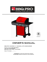
Refer to the this table when designing the island unit
for the BTE2616BLP/NG, BTE3216BLP/NG & BTE3816BLP/NG.
Side* and Rear* show the minimum amount of distance
the unit must be from combustibles (ex. Vinyl or wood
siding, fences and overhangs) or sources of ignition (ex.
Pilot lights on water heaters and live electrical
appliances). Height* shows the minimum height the
island unit must be starting from the ground up.
7" minimum clearance
from cutout (for lid)
Side*
Depth
Height
Width
Non-combustible
Construction
Rear*
Height*
Model Height Width Depth Side* Rear*Height*
BTE2616
BLP/NG
9-1/2"24-1/2"19-3/4" 36" 36" 29"
BTE3216
BLP/NG
9-1/2"30-1/2"19-3/4" 36" 36" 29"
BTE3816
BLP/NG
9-1/2" 38" 19-3/4" 36" 36" 29"
!
WARNING
!

20
USE AND CARE INSTRUCTIONS
Brush soapy solution onto LP Gas tank in the ar-
eas indicated by the arrows. See diagram.
If growing bubbles appear do not use or move the
LP Gas tank. Call an LP Gas Supplier or your Fire
Department.
NOTE about LP Gas Tank Exchange Programs
Many retailers that sell grills offer you the option of re-
placing your empty LP Gas tank through an exchange
service. Use only those reputable exchange compa-
nies that inspect, precision fill, test and certify their tanks.
Exchange your tank only for an OPD safety feature-
equipped tank as described in the LP Gas tank section
of this guide.
Ÿ
How to Leak Test your LP Gas Tank
Use a clean paintbrush and a 50/50 mild soap and
water solution.
Ÿ
Ÿ
Ÿ
For your safety:
Leak test new and exchanged LP Gas tanks BEFORE
connecting one to your grill.
Always keep new and exchanged LP Gas tanks in an
upright position during use, transit or storage.
All leak tests must be repeated each time your LP Gas
tank is exchanged or refilled.
When checking for gas leaks do not smoke.
Do not use an open flame to check for gas leaks.
Your grill must be leak tested outdoors in a well-ven-
tilated area, away from ignition sources such as gas
fired or electrical appliances. During the leak test, keep
your grill away from open flames or sparks.
Do not use household cleaning agents. Damage to
gas assembly components can result.
Ÿ
Ÿ
Ÿ
Ÿ
If growing bubbles appear do not use or move the
LP Gas tank. Contact an LP Gas Supplier or your
fire department!
WARNING
!
!
Secure a 20lb LP Gas Tank to Gas Grill
(for BTE2616
(A,B)
LP, BTE3216
(A,B)
LP & BTE3816BLP)
NOTE: When using Liquid Propane, EXTREME CAU-
TION should be used to provide ample ventilation of
vapor from the enclosure. LP Gas vapor is heavier
than air and SERIOUS INJURY from a DANGEROUS
EXPLOSION could occur if LP Gas is allowed to
accumulate in an enclosure and then ignited. Both the
Barbecue enclosure and LP cylinder enclosure re-
quire venting that must be provided at the floor level
of the enclosure to allow any leaking LP Gas vapor
to escape (see Fig. 1).
NOTE: When installing a barbecue equipped for liquid
propane(LP) in an island, the propane tank must be
in a separate enclosure that is completely isolated
from the barbecue. It must be cross-ventilated in
accordance with the current standards. The propane
tank MUST NEVER be installed directly under the
barbecue.
NOTE: The total of the upper ventilation openings
must be a minimum of 20 sq. inches. The total of
the lower ventilation openings must be a minimum
of 10 sq. inches. Upper and lower ventilation open-
ings MUST BE PROVIDED on both sides of built-in
construction. The top of the upper ventilation openings
must be located within 5" from the top of the island.
The bottom of the lower ventilation openings must be
at least 1" or less from the floor of the island. The
top of the lower ventilation openings cannot be more
than 5" from the floor of the island. Every ventilation
opening must be a minimum of 1/8". (See Fig. 6 on
page 17). Please ask Barbeques Galore's associate
for more details.
LP Gas Model only:
Note: You can only use a 20lb LP Gas Tank in this Gas
Grill.
Fig. 1
5/8" UNF Male
Thread
Air Vents
CSA Approved Stainless
Steel Flexible Connector
Air Vents
Non-Combustible
Construction, such as
stone, marble, cement
Clamp down
flexline
The built-in appliance for use with a remote self-contained LP
Gas supply system must use rigid pipe, semi-rigid tubing or a
connector complying with the Standard for Connections for
Gas Appliances, ANSI Z21.24/CSA6.10, or the standard for
Connectors Outdoor Gas Appliance and Manufactured Homes,
ANSI21.75/CSA 6.27 and suitable for outside installation. The
maximum length of the connection shall be 6 ft(1.82m).
The connector should be installed at the location visible
when opening the door.
The connector must be away from any sharp points or sharp
edges.
When using semi-rigid tubing, do not use materials made of
aluminium or aluminium alloy.
Note:
/