Page is loading ...

Intel
®
Server System
R1000BB Product Family
Technical Product Specification
Revision 2.0
December 2013
Platform Collaboration and Systems Division – Marketing

Intel
®
Server System R1000BB Product Family TPS
ii Revision 2.0
Revision History
Date
Revision Number
Modifications
April 2012
1.0
1
st
Production Release
June 2012 1.1
• Corrected LCP front Panel port definition
• Corrected LCP product code
• Added advisory note to AXXVRAIL feature list
• Corrected IO Module product code definitions in Table 1
January 2013 1.2
• Front bezel badge option diagrams added to section 2.5
• Rail Kit Caution and Advisory notes added to section 2.6
• Added DC power supply specification content to chapter 3
• Updated RSTe support sections in chapter 6
• Removed sections in Chapter 8 – LCP support. Added reference to
published LCP TPS
• Corrected Appendix B - POST Code LED Decoder – (E0h – E3h)
• Added Appendix D. – System Configuration Table for Thermal Compatibility
February 2013 1.2.1
Removed all content and references for DC power supply support.
December 2013 2.0
Added support for Intel
®
Xeon
®
processor E5-2400 v2 product family
Updated chassis air flow specification

Intel
®
Server System R1000BB Product Family TPS
Revision 2.0
iii
Disclaimers
INFORMATION IN THIS DOCUMENT IS PROVIDED IN CONNECTION WITH INTEL PRODUCTS. NO LICENSE, EXPRESS OR
IMPLIED, BY ESTOPPEL OR OTHERWISE, TO ANY INTELLECTUAL PROPERTY RIGHTS IS GRANTED BY THIS DOCUMENT.
EXCEPT AS PROVIDED IN INTEL'S TERMS AND CONDITIONS OF SALE FOR SUCH PRODUCTS, INTEL ASSUMES NO
LIABILITY WHATSOEVER AND INTEL DISCLAIMS ANY EXPRESS OR IMPLIED WARRANTY, RELATING TO SALE AND/OR USE
OF INTEL PRODUCTS INCLUDING LIABILITY OR WARRANTIES RELATING TO FITNESS FOR A PARTICULAR PURPOSE,
MERCHANTABILITY, OR INFRINGEMENT OF ANY PATENT, COPYRIGHT OR OTHER INTELLECTUAL PROPERTY RIGHT.
A "Mission Critical Application" is any application in which failure of the Intel Product could result, directly or indirectly, in personal injury
or death. SHOULD YOU PURCHASE OR USE INTEL'S PRODUCTS FOR ANY SUCH MISSION CRITICAL APPLICATION, YOU
SHALL INDEMNIFY AND HOLD INTEL AND ITS SUBSIDIARIES, SUBCONTRACTORS AND AFFILIATES, AND THE DIRECTORS,
OFFICERS, AND EMPLOYEES OF EACH, HARMLESS AGAINST ALL CLAIMS COSTS, DAMAGES, AND EXPENSES AND
REASONABLE ATTORNEYS' FEES ARISING OUT OF, DIRECTLY OR INDIRECTLY, ANY CLAIM OF PRODUCT LIABILITY,
PERSONAL INJURY, OR DEATH ARISING IN ANY WAY OUT OF SUCH MISSION CRITICAL APPLICATION, WHETHER OR NOT
INTEL OR ITS SUBCONTRACTOR WAS NEGLIGENT IN THE DESIGN, MANUFACTURE, OR WARNING OF THE INTEL PRODUCT
OR ANY OF ITS PARTS.
Intel may make changes to specifications and product descriptions at any time, without notice. Designers must not rely on the absence
or characteristics of any features or instructions marked "reserved" or "undefined". Intel reserves these for future definition and shall
have no responsibility whatsoever for conflicts or incompatibilities arising from future changes to them. The information here is subject
to change without notice. Do not finalize a design with this information.
The products described in this document may contain design defects or errors known as errata which may cause the product to deviate
from published specifications. Current characterized errata are available on request.
Contact your local Intel sales office or your distributor to obtain the latest specifications and before placing your product order.
Copies of documents which have an order number and are referenced in this document, or other Intel literature, may be obtained by
calling 1-800-548-4725, or go to: http://www.intel.com/design/literature
.

Intel
®
Server System R1000BB Product Family TPS
iv Revision 2.0
Table of Contents
1. Introduction ........................................................................................................................ 1
1.1 Chapter Outline ...................................................................................................... 1
1.2 Server Board Use Disclaimer ................................................................................. 1
1.3 Product Errata ........................................................................................................ 1
2. Product Family Overview ................................................................................................... 2
2.1 Chassis Dimensions ............................................................................................... 4
2.2 System Level Environmental Limits ........................................................................ 5
2.3 System Features and Options Overview ................................................................ 6
2.3.1 Hot Swap Hard Drive Bay and Front Panel Options ............................................... 6
2.3.2 Back Panel Features .............................................................................................. 7
2.3.3 Front Control Panel Options ................................................................................... 7
2.4 Server Board Features Overview ........................................................................... 8
2.5 Available Front Bezel Support .............................................................................. 11
2.6 Available Rack and Cabinet Mounting Kit Options ................................................ 12
3. Power Subsystem ............................................................................................................. 13
3.1 Mechanical Overview ........................................................................................... 13
3.2 Main Power Inter-Connect Layout ........................................................................ 15
3.3 Power Connectors ................................................................................................ 15
3.3.1 Power Supply Module Card Edge Connector ....................................................... 15
3.3.2 Riser Card Power Connectors .............................................................................. 16
3.3.3 Hot Swap Backplane Power Connector ................................................................ 16
3.3.4 Optical Drive Power Connector ............................................................................ 16
3.4 Power Supply Module Efficiency .......................................................................... 17
3.5 Power Cord Specification Requirements .............................................................. 17
3.6 Optional Chassis Grounding Support ................................................................... 17
3.7 AC Input Requirement .......................................................................................... 18
3.7.1 Power Factor ........................................................................................................ 18
3.7.2 AC Input Voltage Specification ............................................................................. 18
3.7.3 AC Line Isolation Requirements ........................................................................... 18
3.7.4 AC Line Dropout / Holdup .................................................................................... 18
3.7.5 AC Line Fuse ....................................................................................................... 19
3.7.6 AC Inrush ............................................................................................................. 19
3.7.7 AC Line Transient Specification ........................................................................... 19
3.7.8 Susceptibility Requirements ................................................................................. 19
3.7.9 Electrostatic Discharge Susceptibility ................................................................... 20
3.7.10 Fast Transient/Burst ............................................................................................. 20
3.7.11 Radiated Immunity ............................................................................................... 20
3.7.12 Surge Immunity .................................................................................................... 20

Intel
®
Server System R1000BB Product Family TPS
Revision 2.0
v
3.7.13 Power Recovery ................................................................................................... 20
3.7.14 Voltage Interruptions ............................................................................................ 20
3.7.15 Protection Circuits ................................................................................................ 20
3.7.16 Over-current Protection (OCP) ............................................................................. 20
3.7.17 Over-voltage Protection (OVP) ............................................................................. 21
3.7.18 Over-temperature Protection (OTP) ..................................................................... 21
3.8 Cold Redundancy Support ................................................................................... 21
3.8.1 Powering on Cold Standby supplies to maintain best efficiency ........................... 21
3.8.2 Powering on Cold Standby supplies during a fault or over current condition ......... 22
3.8.3 BMC Requirements .............................................................................................. 22
3.8.4 Power Supply Turn On Function .......................................................................... 22
3.9 Closed Loop System Throttling (CLST) ................................................................ 22
3.10 Smart Ride Through Throttling (SmaRT) .............................................................. 22
3.11 Power Supply Status LED .................................................................................... 23
4. Thermal Management ....................................................................................................... 24
4.1 Thermal Operation and Configuration Requirements ............................................ 24
4.2 Thermal Management Overview .......................................................................... 25
4.2.1 Set Throttling Mode .............................................................................................. 25
4.2.2 Altitude ................................................................................................................. 25
4.2.3 Set Fan Profile ..................................................................................................... 25
4.2.4 Fan PWM Offset ................................................................................................... 26
4.2.5 Quiet Fan Idle Mode ............................................................................................. 26
4.3 System Fans ........................................................................................................ 27
4.4 Power Supply Fans .............................................................................................. 29
4.5 FRUSDR Utility .................................................................................................... 29
5. System Storage and Peripheral Options ......................................................................... 30
5.1 2.5” Hard Disk Drive Support ................................................................................ 30
5.1.1 2.5” Drive Hot-Swap Backplane Overview ............................................................ 31
5.1.2 Cypress* CY8C22545 Enclosure Management Controller .................................... 32
5.2 3.5” Hard Disk Drive Support ................................................................................ 33
5.2.1 2.5” Drive Hot-Swap Backplane Overview ............................................................ 34
5.2.2 Cypress* CY8C22545 Enclosure Management Controller .................................... 35
5.3 Optical Drive Support ........................................................................................... 35
5.4 eUSB SSD Support .............................................................................................. 36
5.5 SATA DOM Support ............................................................................................. 36
5.6 mSATA SSD Support ........................................................................................... 37
6. Storage Controller Options Overview ............................................................................. 38
6.1 Embedded SATA / SAS Controller support .......................................................... 38
6.2 Embedded Software RAID Support ...................................................................... 39
6.2.1 Intel
®
Embedded Server RAID Technology 2 (ESRT2)
1
....................................... 39
6.2.2 Intel
®
Rapid Storage Technology (RSTe)
1
............................................................ 39

Intel
®
Server System R1000BB Product Family TPS
vi Revision 2.0
6.3 Intel
®
Integrated RAID Module Support (Available Option) ................................... 40
7. Front Control Panel and I/O Panel Overview .................................................................. 41
7.1 I/O Panel Features ............................................................................................... 41
7.2 Control Panel Features ........................................................................................ 42
8. Intel
®
Local Control Panel ................................................................................................ 45
9. PCI Riser Card Support .................................................................................................... 46
9.1 Architectural Overview of the Server Board Riser Slots ........................................ 46
9.2 Riser Card Support .............................................................................................. 48
9.3 Riser Card Options – Riser Slot #1 ....................................................................... 48
9.4 Riser Card Options – Riser Slot #2 ....................................................................... 49
9.4.1 1-Slot PCIe x8 Riser Card (default) ...................................................................... 49
9.4.2 1-Slot PCIe x16 Riser Card (option) ..................................................................... 50
9.4.3 2-Slot Butterfly Riser Card (option) ....................................................................... 50
10. Mezzanine Module Support .............................................................................................. 52
10.1 IO Module Support ............................................................................................... 52
10.2 Intel
®
Remote Management Module 4 (RMM4) Lite and Management NIC Support52
Appendix A: Integration and Usage Tips .............................................................................. 54
Appendix B: POST Code Diagnostic LED Decoder .............................................................. 55
Appendix C: POST Code Errors ............................................................................................. 60
Appendix D: System Configuration Table for Thermal Compatibility ................................ 65
Glossary .................................................................................................................................... 68
Reference Documents .............................................................................................................. 69

Intel
®
Server System R1000BB Product Family TPS
Revision 2.0
vii
List of Figures
Figure 1. Chassis Dimensions ..................................................................................................... 4
Figure 2. System Components Overview .................................................................................... 6
Figure 3. 3.5" Hard Drive Bay - 4 Drive Configuration ................................................................. 6
Figure 4. 2.5" Hard Drive Bay - 8 Drive Configuration ................................................................. 7
Figure 5. Back Panel Feature Identification ................................................................................. 7
Figure 6. Front Control Panel Options ......................................................................................... 7
Figure 7. Intel
®
Server Board S2400BB ....................................................................................... 9
Figure 8. Intel
®
Light-Guided Diagnostic LEDs - Server Board .................................................... 9
Figure 9. Optional Front Bezel .................................................................................................. 11
Figure 10. Front Bezel accessory with optionally installed wave feature.................................... 11
Figure 11. Front Bezel accessory with optionally installed wave and ID badge (1) .................... 11
Figure 12. Front Bezel accessory with optionally installed wave and ID badge (2) .................... 11
Figure 13. Front Bezel accessory ID Badge mechanical drawings ............................................ 12
Figure 14. Power Supply Module Mechanical Drawing .............................................................. 14
Figure 15. Power Supply Module .............................................................................................. 14
Figure 16. AC Power Supply - Connector View ......................................................................... 14
Figure 17. Main Power Connector Identification ........................................................................ 15
Figure 18. AC Power Cord ........................................................................................................ 17
Figure 19. Chassis Grounding Studs ......................................................................................... 17
Figure 20. Fan Control Model .................................................................................................... 27
Figure 21. System Fan Identification ......................................................................................... 27
Figure 22. Server Board System Fan Connector Locations ....................................................... 28
Figure 23. 2.5" Hard Drive Bay Drive Configuration .................................................................. 30
Figure 24. 3.5" Hard Drive Bay Configuration ............................................................................ 33
Figure 25. Optical Drive Support ............................................................................................... 35
Figure 26. Low Profile eUSB SSD Support ............................................................................... 36
Figure 27. InnoDisk* Low Profile SATA DOM ............................................................................ 36
Figure 28. mSATA Placement ................................................................................................... 37
Figure 29. AXXBBU09 and AXXRFMBU2 Installation ............................................................... 41
Figure 30. Front I/O Panel Features .......................................................................................... 41
Figure 31. Front Control Panel Features ................................................................................... 42
Figure 32. Intel
®
Local Control Panel Option ............................................................................. 45
Figure 33. Riser Slot Architecture – Intel® C600 Upgrade Key NOT installed ........................... 46
Figure 34. Riser Slot Architecture – Intel® C600 Upgrade Key Installed ................................... 46
Figure 35. Intel® Server Board S2400BB PCI Bus Layout Diagram .......................................... 47
Figure 36. Add-in Card Support ................................................................................................ 48
Figure 37. 1U Riser Card #1 Assembly Drawing ....................................................................... 49
Figure 38. 1U Butterfly Riser Card #2 Assembly – Back Side View ........................................... 50

Intel
®
Server System R1000BB Product Family TPS
viii Revision 2.0
Figure 39. 1U Butterfly Riser Card #2 Assembly - Front Side View ........................................... 51
Figure 40. Intel® RMM4 Lite Activation Key Installation ........................................................... 53
Figure 41. Intel® RMM4 Dedicated Management NIC Installation ............................................. 53
Figure 42. POST Diagnostic LEDs ............................................................................................ 55

Intel
®
Server System R1000BB Product Family TPS
Revision 2.0
ix
List of Tables
Table 1. System Feature Set ....................................................................................................... 3
Table 2. System Environmental Limits Summary ........................................................................ 5
Table 3. Power Supply Module Output Power Connector Pin-out ............................................. 15
Table 4. Riser Slot Power Pin-out ("OPT_12V_PWR_#") .......................................................... 16
Table 5. Hot Swap Backplane Power Connector Pin-out (“HSBP PWR") .................................. 16
Table 6. Peripheral Drive Power Connector Pin-out ("ODD/SSD PWR") ................................... 16
Table 7. 460 Watt AC Power Supply Efficiency ........................................................................ 17
Table 8. 750 Watt AC Power Supply Efficiency ......................................................................... 17
Table 9. AC Power Cord Specifications.................................................................................... 17
Table 10. AC Input Voltage Range ............................................................................................ 18
Table 11. AC Line Sag Transient Performance ........................................................................ 19
Table 12. AC Line Surge Transient Performance ..................................................................... 19
Table 13. Performance Criteria ................................................................................................ 19
Table 14. 460 Watt Power Supply Over Current Protection ...................................................... 20
Table 15. 750 Watt Power Supply Over Current Protection ....................................................... 20
Table 16. Over Voltage Protection (OVP) Limits ...................................................................... 21
Table 17. Example Load Share Threshold for Activating Supplies ........................................... 22
Table 18. LED Indicators ........................................................................................................... 23
Table 19. System Fan Connector Pin-out .................................................................................. 29
Table 20. Drive Status LED States ............................................................................................ 31
Table 21. Drive Activity LED States ........................................................................................... 31
Table 22. Intel® RAID C600 Upgrade Key Options ................................................................... 38
Table 23. Supported Intel® Integrated RAID Modules ............................................................... 40
Table 24. System Status LED State Definitions......................................................................... 43
Table 25. Power/Sleep LED Functional States .......................................................................... 44
Table 26. Enabling Advanced Management Features ............................................................... 53
Table 27. POST Progress Code LED Example ......................................................................... 55
Table 28. Diagnostic LED POST Code Decoder ....................................................................... 56
Table 29. MRC Progress Codes ............................................................................................... 58
Table 30. MRC Fatal Error Codes ............................................................................................. 59
Table 31. POST Error Messages and Handling ......................................................................... 60
Table 32. POST Error Beep Codes ........................................................................................... 64
Table 33. Integrated BMC Beep Codes ..................................................................................... 64

Intel
®
Server System R1000BB Product Family TPS
x Revision 2.0
< This page intentionally left blank. >

Intel
®
Server System R1000BB Product Family TPS
Revision 2.0 1
1. Introduction
This Technical Product Specification (TPS) provides system level information for the Intel
®
Server System
R1000BB product family. It describes the functions and features of the integrated server system which includes
the chassis layout, system boards, power sub-system, cooling sub-system, storage sub-system options, and
available installable options. Server board specific detail can be obtained by referencing the Intel
®
Server
Board S2400BB Technical Product Specification.
In addition, design-level information related to specific server board components / subsystems can be obtained
by ordering External Product Specifications (EPS) or External Design Specifications (EDS) related to this
server generation. EPS and EDS documents are made available under NDA with Intel and must be ordered
through your local Intel
representative. See the Reference Documents section at the end of this document for a
complete list of available documents.
1.1 Chapter Outline
This document is divided into the following chapters:
Chapter 1 – Introduction
Chapter 2 – Product Family Overview
Chapter 3 – Power Subsystem
Chapter 4 – Thermal Management
Chapter 5 – System Storage and Peripherals Drive Bay Overview
Chapter 6 – Storage Controller Options Overview
Chapter 7 – Front Control Panel and I/O Panel Overview
Chapter 8 – Intel
®
Local Control Panel
Chapter 9 – PCI Riser Card Support
Chapter 10 – Mezzanine Module Support
Appendix A – Integration and Usage Tips
Appendix B – POST Code Diagnostic LED Decoder
Appendix C – Post Code Errors
Appendix D – System Configuration Table for Thermal Compatibility
Glossary
Reference Documents
1.2 Server Board Use Disclaimer
Intel Corporation server boards support add-in peripherals and contain a number of high-density VLSI and
power delivery components that need adequate airflow to cool. Intel
®
ensures through its own chassis
development and testing that when Intel
®
server building blocks are used together, the fully integrated system
will meet the intended thermal requirements of these components. It is the responsibility of the system
integrator who chooses not to use Intel
®
-developed server building blocks to consult vendor datasheets and
operating parameters to determine the amount of airflow required for their specific application and
environmental conditions. Intel Corporation cannot be held responsible if components fail or the server board
does not operate correctly when used outside any of their published operating or
non-operating limits.
1.3 Product Errata
The products described in this document may contain design defects or errors known as errata which may
cause the product to deviate from published specifications. Product Errata are documented in the Intel
®
Server
Board S2400BB, Intel
®
Server System R1000BB, Intel
®
Server System R2000BB Monthly Specification Update
which can be downloaded from http://www.intel.com/support
.

Intel
®
Server System R1000BB Product Family TPS
2 Revision 2.0
2. Product Family Overview
This generation of Intel 1U server platforms offers a variety of system options to meet the varied configuration
requirements of high-density high-performance computing environments. The Intel
®
Server System R1000BB
product family is comprised of several available 1U rack mount server systems that are all integrated with an
Intel
®
Server Board S2400BB.
This chapter provides a high-level overview of the system features and available options as supported in
different platform SKUs within this server family. Greater detail for each major system component or feature is
provided in the following chapters.

Intel
®
Server System R1000BB Product Family TPS
Revision 2.0 3
Table 1. System Feature Set
Server System
Integrated Server Board
Intel
®
Server System R1000BB product family Intel
®
Server Board S2400BB
Feature
Description
Processor Support
Support for one or two processors:
Intel
®
Xeon
®
processor E5-2400 product family with TDP support of up to 95 W
Intel
®
Xeon
®
processor E5-2400 v2 product family with TDP support of up to 95 W
Memory
12 DIMM slots – 2 DIMMs / Channel – 3 memory channels per processor
Unbuffered DDR3 (UDIMM), registered DDR3 (RDIMM), and Load Reduced DDR3 (LRDIMM)
Memory DDR3 data transfer rates of 800, 1066, 1333, and 1600 MT/s
DDR3 standard I/O voltage of 1.5V and DDR3 Low Voltage of 1.35V
Chipset Intel
®
C602 chipset with support for optional Intel
®
RAID C600 Upgrade keys
External I/O
connections
Video (back and front video connectors)
RJ-45 Serial- A Port
Four RJ-45 Network Interface Connectors supporting 10/100/1000Mb
USB 2.0 connectors - 3 on back panel + 2 on front panel
Internal I/O
connectors / headers
One Type-A USB 2.0 connector
One DH-10 Serial-B port connector
I/O Module
Accessory Options
The following I/O modules utilize a single proprietary on-board connector. An installed I/O module can
be supported in addition to standard on-board features and any add-in expansion cards.
Quad port 1 GbE based on Intel® Ethernet Controller I350 – AXX4P1GBPWLIOM
Dual RJ-45 port 10GBase-T I/O Module based on Intel
®
Ethernet Controller x540 –
AXX10GBTWLIOM
Dual SFP+ port 10GbE module based on Intel® 82599 10 GbE controller – AXX10GBNIAIOM
Single Port FDR 56GT/S speed InfiniBand module with QSFP connector – AXX1FDRIBIOM
Dual port FDR 56GT/S speed infiniband module with QSFP connector – AXX2FDRIBIOM
System Fans
Five dual rotor managed system fans
One power supply fan for each installed power supply module
Riser Cards
Support for two PCIe riser cards. Riser cards for Riser #1 and Riser #2 are not the same.
• Riser Slot #1 (PCIe x16): Single add-in card slot – PCIe x16 lanes, x16 slot
• Riser Slot #2 (PCIe x24): Supported riser cards for this slot include:
o Single add-in card slot – PCIe x8 lanes, x16 slot
o Single add-in card slot – PCIe x16 lanes, x16 slot (dual CPU configurations only)
o Butterfly Riser Card (Accessory Option) -: Two add-in card slots: one PCIe x16
lanes, x16 slot and one PCIe x8 lanes, x8 slot. Note: The PCIe x8 add-in card slot is
designed specifically for an Intel® Integrated RAID Module.
Video
Integrated 2D Video Controller
16 MB DDR3 Memory
On-board storage
controllers and
options
One eUSB 2x5 pin connector to support 2mm low-profile eUSB solid state devices
One mSATA SSD connector
One 7-pin single port AHCI SATA connectors capable of supporting up to 6 Gb/sec
Two SCU 4-port mini-SAS connectors capable of supporting up to 3 Gb/sec SAS/SATA
o SCU 0 Port (Enabled standard)
o SCU 1 Port (Requires Intel RAID C600 Upgrade Key)
Intel
®
RAID C600 Upgrade Key support providing optional expanded SATA / SAS RAID capabilities
Security Intel
®
TPM module – AXXTPME5 (Accessory Option)
Server Management
Integrated Baseboard Management Controller, IPMI 2.0 compliant
Support for Intel® Server Management Software
Intel
®
Remote Management Module 4 Lite – Accessory option
Intel
®
Remote Management Module 4 Management NIC – Accessory option

Intel
®
Server System R1000BB Product Family TPS
4 Revision 2.0
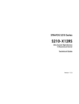
2.1 Chassis Dimensions
Power Supply
Options
The server system can have up to two power supply modules installed, providing support for the
following power configurations: 1+0, 1+1 Redundant Power, and 2+0 Combined Power
Three power supply options:
o AC 460W Gold
o AC 750W Platinum
Storage Bay Options
4x – 3.5” SATA/SAS Hot Swap Hard Drive Bays + Optical Drive support
8x – 2.5” SATA/SAS Hot Swap Hard Drive Bays + Optical Drive support (capable)
Supported Rack
Mount Kit Accessory
Options
Tool-less rack mount rail kit – Intel Product Code – AXXPRAIL
Value rack mount rail kit – Intel Product Code – AXXVRAIL
Cable Management Arm – Intel Product Code – AXX1U2UCMA (*supported with AXXPRAIL only)
2-post fixed mount bracket kit – Intel Product Code – AXX2POSTBRCKT
Figure 1. Chassis Dimensions

Intel
®
Server System R1000BB Product Family TPS
Revision 2.0 5
2.2 System Level Environmental Limits
The following table defines the system level operating and non-operating environmental limits.
Table 2. System Environmental Limits Summary
Parameter
Limits
Temperature
Operating ASHRAE Class A2 – Continuous Operation. 10º C to 35º C (50º F to 95º F) with the maximum
rate of change not to exceed 10°C per hour
ASHRAE Class A3 – Includes operation up to 40C for up to 900 hrs per year.
ASHRAE Class A4 – Includes operation up to 45C for up to 90 hrs per year.
Shipping -40º C to 70º C (-40º F to 158º F)
Altitude
Operating Support operation up to 3050m with ASHRAE class deratings.
Humidity
Shipping 50% to 90%, non-condensing with a maximum wet bulb of 28° C (at temperatures from 25° C
to 35° C)
Shock
Operating Half sine, 2g, 11 mSec
Unpackaged Trapezoidal, 25 g, velocity change is based on packaged weight
Packaged Product Weight: ≥ 40 to < 80
Non-palletized Free Fall Height = 18 inches
Palletized (single product) Free Fall Height = NA
Vibration
Unpackaged 5 Hz to 500 Hz 2.20 g RMS random
Packaged 5 Hz to 500 Hz 1.09 g RMS random
AC-DC
Voltage 90 Hz to 132 V and 180 V to 264 V
Frequency 47 Hz to 63 Hz
Source Interrupt No loss of data for power line drop-out of 12 mSec
Surge Non-
operating and
operating
Unidirectional
Line to earth Only AC Leads 2.0 kV
I/O Leads 1.0 kV
DC Leads 0.5 kV
ESD
Air Discharged 12.0 kV
Contact
Discharge
8.0 kV
Air Flow
Operation 10-55 CFM
Acoustics
Sound Power
Measured
Power in Watts <300 W ≥300 W ≥600 W ≥1000 W
Servers/Rack
Mount BA
7.0 7.0 7.0 7.0

Intel
®
Server System R1000BB Product Family TPS
6 Revision 2.0
See Appendix D in this document or the Intel
®
S2400BB Product Family Power Budget and Thermal
Configuration Tool for system configuration requirements and limitations.
2.3 System Features and Options Overview
Figure 2. System Components Overview
2.3.1 Hot Swap Hard Drive Bay and Front Panel Options
Figure 3. 3.5" Hard Drive Bay - 4 Drive Configuration

Intel
®
Server System R1000BB Product Family TPS
Revision 2.0 7
Figure 4. 2.5" Hard Drive Bay - 8 Drive Configuration
2.3.2 Back Panel Features
Figure 5. Back Panel Feature Identification
2.3.3 Front Control Panel Options
Label
Description
Label
Description
A System ID Button w/Integrated LED F System Status LED
B NMI Button (recessed, tool required for use) G Power Button w/Integrated LED
C NIC-1 Activity LED H Hard Drive Activity LED
D NIC-3 Activity LED I NIC-4 Activity LED
E System Cold Reset Button J NIC-2 Activity LED
Figure 6. Front Control Panel Options

Intel
®
Server System R1000BB Product Family TPS
8 Revision 2.0
2.4 Server Board Features Overview
The following illustration provides a general overview of the server board, identifying key feature and
component locations.

Intel
®
Server System R1000BB Product Family TPS
Revision 2.0 9
Figure 7. Intel
®
Server Board S2400BB
Figure 8. Intel
®
Light-Guided Diagnostic LEDs - Server Board

Intel
®
Server System R1000BB Product Family TPS
10 Revision 2.0
/