Page is loading ...


C320 Turbo/PCI User’s Manual
The software described in this manual is furnished under a license agreement and may be used only in accordance
with the terms of that agreement.
Copyright Notice
Copyright © 2008 Moxa Inc.
All rights reserved.
Reproduction without permission is prohibited.
Trademarks
MOXA is a registered trademark of Moxa Inc.
All other trademarks or registered marks in this manual belong to their respective manufacturers.
Disclaimer
Information in this document is subject to change without notice and does not represent a commitment on the part of
Moxa.
Moxa provides this document “as is,” without warranty of any kind, either expressed or implied, including, but not
limited to, its particular purpose. Moxa reserves the right to make improvements and/or changes to this manual, or to
the products and/or the programs described in this manual, at any time.
Information provided in this manual is intended to be accurate and reliable. However, Moxa assumes no
responsibility for its use, or for any infringements on the rights of third parties that may result from its use.
This product might include unintentional technical or typographical errors. Changes are periodically made to the
information herein to correct such errors, and these changes are incorporated into new editions of the publication.
Technical Support Contact Information
www.moxa.com/support
Moxa Americas:
Toll-free: 1-888-669-2872
Tel: +1-714-528-6777
Fax: +1-714-528-6778
Moxa China (Shanghai office)
:
Toll-free: 800-820-5036
Tel: +86-21-5258-9955
Fax: +86-10-6872-3958
Moxa Europe
:
Tel: +49-89-3 70 03 99-0
Fax: +49-89-3 70 03 99-99
Moxa Asia-Pacific
:
Tel: +886-2-8919-1230
Fax: +886-2-8919-1231

About This Manual
This manual is composed of six Chapters and one Appendix. This manual is written for installer, system
administrator and software programmer.
If you are a first-time installer and system administrator, we recommend you to go through the whole
manual except Chapter 4.
If you are a software programmer, you may refer to Chapter 4 “Serial Programming Tools”.
If you need cable wiring information, please see Chapter 5 “Connection Option (Opt8x) and Cable
Wiring”.
If you encounter any problem during installation, please refer to Chapter 6 “Troubleshooting”.
☞ In this manual, C320Turbo Series refers to C320Turbo and C320Turbo/PCI.
Chapter 1 Introduction
Overview and features for C320Turbo/PCI are described. Also check list and overall installation
guide.
Chapter 2 Hardware Installation
Hardware installation for C320Turbo/PCI .
Chapter 3 Software Installation
This Chapter details the software installation, configuration, driver loading/unloading, driver upgrade
and removal for various operating systems: Windows NT, Windows 95/98 and UNIX.
Chapter 4 Serial Programming Tools
This Chapter roughly describes the programming tools for various O.S. platforms, including PComm
under Windows NT, Windows 95/98 and standard UNIX system calls.
Chapter 5 Connection Option and Cable Wiring
This Chapter describes the RS-232/422 cable wiring for the connection options.
Chapter 6 Troubleshooting
This Chapter describes the problems and possible answers for C320Turbo/PCI.
Appendix
Specification details, PCI, Dual-Ported RAM, and UART are described.

Table of Contents
Introduction
IntroductionIntroduction
Introduction ............................................................................................... 1-1
Overview................................................................................................................1-1
Features................................................................................................................. 1-4
Check List..............................................................................................................1-5
Installation Guide...................................................................................................1-6
Hardware Installation
Hardware InstallationHardware Installation
Hardware Installation............................................................................. 2-1
Installing the Intellio C320Turbo/PCI Control Board...............................................2-1
Installing the External Modules ..............................................................................2-2
Installing the CPU and UART Modules (Desktop)...............................................................2-2
Installing the Basic and Extensive Modules (Rackmount)...................................................2-5
Operating LED Indicators.......................................................................................2-8
Mix of Various UART Modules............................................................................. 2-10
Software Installation
Software InstallationSoftware Installation
Software Installation.............................................................................. 3-1
Windows NT ..........................................................................................................3-1
Installing Driver....................................................................................................................3-2
Configuring Board and Port.................................................................................................3-7
Adding/Removing Board......................................................................................................3-9
Updating Driver....................................................................................................................3-9
Removing Driver..................................................................................................................3-9
Windows 95/98.................................................................................................... 3-10
Installing Driver..................................................................................................................3-10
Configuring Board and Port...............................................................................................3-19
Updating driver ..................................................................................................................3-23
Removing driver ................................................................................................................3-23
UNIX.................................................................................................................... 3-24
Installing Driver..................................................................................................................3-24
MOXA TTY Device Naming Convention............................................................................3-27
Administration Utility - mxadm...........................................................................................3-28
Checking Board Initialization Status..................................................................................3-34
Setting MOXA Ports to Terminal .......................................................................................3-34

Serial Programming Tools
Serial Programming ToolsSerial Programming Tools
Serial Programming Tools..................................................................... 4-1
Windows NT and Windows 95/98.......................................................................... 4-1
Installation............................................................................................................................4-1
PComm Programming Library.............................................................................................4-2
Utilities.................................................................................................................................4-2
UNIX...................................................................................................................... 4-5
Programming the MOXA Ports............................................................................................4-5
Extended UNIX Ioctl() Commands......................................................................................4-5
Utilities...............................................................................................................................4-11
Connection Option and Cable Wiring
Connection Option and Cable WiringConnection Option and Cable Wiring
Connection Option and Cable Wiring
....................................................... 5-1
RS-232 Cable Wiring for C32045T/C32047T/C32071T ......................................... 5-1
RS-422 Cable Wiring for C32061T/C32065T.........................................................5-7
RS-232 Cable Wiring for C32080T/81T/82T/83T & CN20040.............................. 5-10
C32020T Link Cable............................................................................................ 5-14
Troubleshooting
TroubleshootingTroubleshooting
Troubleshooting ....................................................................................... 6-1
General Troubleshooting........................................................................................ 6-1
Windows NT ..........................................................................................................6-5
Windows 95/98......................................................................................................6-7
UNIX...................................................................................................................... 6-8
Technical Reference
Technical ReferenceTechnical Reference
Technical Reference...............................................................................A-1
Specifications.........................................................................................................A-1
PCI.........................................................................................................................A-5
Dual-Ported RAM...................................................................................................A-5
TI550C in UART/Basic/Extensive Modules ............................................................A-6

Intellio C320Turbo/P User's Manual 1-1
1
11
1
1
11
1
1 Introduction
This manual covers both the hardware and software installation and configuration of
C320Turbo/PCI, which is the member of the Intellio Family. In addition, the
professional serial comm tools, PComm under Windows NT and Windows 95/98 and
extended UNIX system calls, and utilities are introduced.
Overview
The excellent features, described below, make Intellio C320Turbo/PCI the best
choice for medium to large-scale data communication systems from 8 to 128 serial
ports.
Intellio - The Intelligent 8-32 Port Serial I/O Solution
The Intellio C320Turbo/PCI is an intelligent dual-CPU high-speed expandable
multi-serial communication controller, which aims to gain higher speed, achieve
better performance and lessen the load of the host system.
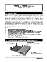
Port Expandable
The Intellio C320Turbo/PCI is composed of a Control Board, a DB25 to DB25
cable, some external modules. The Intellio C320Turbo/PCI supports expandability
from 8 to 32 ports for a single PC slot. Up to 128 ports could be used in the PC with
four Intellio C320Turbo/PCI installed.
PCI Solution
The board complies with PCI Spec. 2.1 and has neither switch nor jumper. Hardware
configuration for the IRQ number and memory addresses is automatically assigned
by PCI BIOS. Hence, it is a must to have the board plugged first before installing
software driver. For more PCI information, see appendix.

1-2 Intellio C320Turbo/PCI User's Manual
Low Host Processor Overhead
The Intellio C320Turbo/PCI is equipped with two high performance processors
(TMS320) on both the Control Board and the CPU/Basic Module and 512KB on-
board memory to relieve the host’s CPU workload of all data and I/O handling tasks.
The memory buffer holds transmitted and received data to prevent data loss.
ASIC Design, Compact Size
The Intellio C320Turbo/PCI is also equipped with MOXA custom-designed ASIC
chip, which replaces lots of conventional IC and hence reduces the board to half-
size, increases the operation performance, and lowers the failure rate of the board.
Distance Extensible
Normally, a standard 2-meter DB25 to DB25 cable with 25 signal pins links the
Control Board to the external module. However, for the purpose of extending the
distance between Control Board and external modules to above 2 m and up to 100 m
(328 ft) or improving power insufficiency problem of the PC host, external power
and the cable specially fabricated with only 10 signal pins should be used as
illustrated in chapter 2 and chapter 5.
Versatile Connection Options
There are two connection options, Desktop and Rackmount, for the external
modules to meet various connection requirements. For Desktop option, CPU Module
and UART Modules are provided. For Rackmount option, Basic Module and
Extensive Modules are provided with rack mount capability. Besides, you may
choose flexibly from modules with DB25/RJ45, male/female, or RS-232/RS-422.

Introduction
Intellio C320Turbo/PCI User's Manual 1-3
2
3
4
5
6
7
8
1
2
3
4
5
6
7
8
1
Extensive Module
Basic Module
UART
Module
CPU
Module
UART
Module
C320 Turbo/PCI
DB25 to DB25 Cable
Surge/Isolation Protection
To prevent the boards from damage caused by lightning or high potential voltage,
TVSS (Transient Voltage Surge Suppressor) and high potential difference protector
technologies are introduced in some connection options to protect the multiport
controller. This is critical to harsh environment such as factory, severe weather such
as lightning, or other high interference situations.
Status Indicator
The status of the communication lines is displayed on a row of diagnostic LED
indicators on the front panel of the external module, including TxD, RxD, DTR,
DSR, RTS, CTS, and DCD signals.
Major Operating System Support
It supports most popular O.S. platforms like Windows NT, Windows 95/98, SCO
UNIX/OpenServer, UNIX SVR4.2, Linux. MOXA device drivers feature easy
installation, configuration and better performance. In this manual, chapters for
MOXA Windows NT, Windows 95/98, and UNIX device drivers are included. For
other systems not mentioned, please contact Moxa dealer/distributor or Moxa or visit
the MOXA Web site for more information
about newly available device drivers.

1-4 Intellio C320Turbo/PCI User's Manual
Powerful Serial Comm Developing Tools
For application development, MOXA provides the easy-to-use while powerful serial
communication library, including PComm under Windows NT, Windows 95/98 and
extended UNIX system calls. You can use this library to develop applications with
programming languages like Visual C++, Visual Basic, Borland C++, Borland
Delphi, UNIX C, etc. Utilities, such as monitor, terminal emulator, and diagnostics,
are included for debugging or monitoring the communication status or for terminal
emulation or file transferring.
Easy Installation
No matter hardware or software, installation are made as easy as possible. Follow the
installation guide to install and configure the hardware and the driver. Then, you can
start to use Intellio C320Turbo/PCI to transmit/receive data to/from the connected
devices, such as terminals, modems and printers, with ready-made or self-written
application programs.
Broad Applications
The Intellio C320Turbo/PCI is suitable for many applications. Here are a few:
Internet/Intranet Connection
Remote Access Application
Multi-user Application
Industrial Automation
Office Automation
Telecommunication
PC-based (vending) Machine or Kiosk System
Point-of-Sale (POS) System
Features
The following is a summary of all the outstanding features of
Intellio C320 Turbo/PCI:
❖ High speed serial communication-Up to 460.8 Kbps
❖ Low host CPU's overhead-Dual RISC processor architecture
❖ Reliability-On-chip hardware flow control guarantees no data loss
❖ Modular expandability-Easy to add ports for a single PC slot
❖ Supports full communication status display for each port
❖ Long range extensibility-Easy for long distance cable layout

Introduction
Intellio C320Turbo/PCI User's Manual 1-5
❖ Rack mountable-Industrial standard 19” rack
❖ Supports most popular OS-Windows NT, Windows 95/98, UNIX, Linux
❖ Friendly user interface for configuration and utilities
❖ Powerful but easy serial programming library and illustrative examples
Check List
Upon unpacking Intellio C320Turbo/PCI package, you should find the following
items:
❖ One Intellio C320Turbo/PCI Control Board
❖ One CPU Module or Basic Module
❖ One 2-meter DB25 to DB25 cable for connecting Control Board and
CPU/Basic Module. This item may not be needed if long range extension
kit is purchased
❖ For Desktop option, at least one and up to four 8-port RS-232/RS-422
female/male UART Module(s). For Rackmount option, up to 32 ports
of combination of 8-port or 16-port RS-232 Basic/Extensive Module(s).
❖ For Rackmount option, DB-37 to DB-37 cable(s) for connecting
Basic/Extensive Modules, if Extensive Module is used
❖ For Rackmount option, one 1.5-meter RJ-45 to male DB25 RS-232 cable for
testing
❖ Device driver diskettes:
Windows NT and Windows 95/98 Version 4.9 or above×1
PComm Lite Version 2.2 or above×1
UNIX Version 4.10 or above×1
❖ This Intellio C320Turbo/PCI User's Manual
❖ Fixing Kit for Desktop option. Or Rack Mount Kit for Rackmount option.
The following item may be included if long range extension is needed:
❖ Long range extension kit
❖ A power adapter for CPU/Basic Module, 90-240V AC auto-select
❖ A DB25 to DB25 cable which contains only 10 signal pins for connecting
Control Board and CPU/Basic Module

1-6 Intellio C320Turbo/PCI User's Manual
Installation Guide
This section gives a brief summary of how to install the Intellio C320Turbo/PCI
under each supported operating system. Installation is simple and involves the
following stages:
Check the PCI BIOS settings
Install the Intellio C320Turbo/PCI board See chapter 2
and the connection option (cable/module)
Install the software from the diskette See respective O.S. Section
Configure the driver for the board and ports in chapter 3
Connect the devices with the cable See chapter 5 for cable wiring
Restart the system See chapter 3, “Software
Check the driver initialization status Installation”
If the system restarts successfully, you may
develop your applications or See chapter 4, “Serial
execute the desired applications Programming Tools”

Intellio C320Turbo/P User's Manual 2-1
2
22
2
2
22
2
2 Hardware Installation
Hardware InstallationHardware Installation
Hardware Installation
The installation of Intellio C320Turbo/PCI consists of hardware installation and
software installation. For software installation, please refer to the respective section
of operating systems in the next chapter. Hardware installation is stated in this
chapter. The no-switch-no-jumper Intellio C320Turbo/PCI board’s hardware
configuration for IRQ and memory addresses is automatically assigned by PCI
BIOS. Hence, it is a must to have the board plugged first before installing
software driver. After this, simply install the Control Board into the PC and then
connect one of the connection options, Desktop or Rackmount.
The Intellio C320Turbo/PCI hardware installation consists of Control Board
installation and external module installation. Make sure you have connected the
Control Board with proper number of external modules .
Installing the Intellio C320Turbo/PCI Control Board
Step 1: Power off the PC.
Warning ! Make sure you switch off the system before installing
any PCI board.If you don’t, you may risk damaging your
system and the board.
Step 2: Remove the PC’s cover.
Step 3: Remove the slot cover bracket if present.
Step 4: Plug the Intellio C320Turbo/PCI firmly into any free 32-bit PCI slot.
Step 5: Fasten the holding screw to make the Control Board fixed.

2-2 Intellio C320Turbo/PCI User's Manual
Step 6: Replace the system cover.
Note ! Each board must occupy one unique IRQ and one
unique memory address, which are assigned by PCI
BIOS automatically. However, you may select the free
IRQ number manually via PC’s BIOS setup for PCI slot,
but this method is not available for memory. The possible
IRQ numbers are 2(or 9), 3, 4, 5, 7, 10, 11, 12, and 15.
☞
☞☞
☞ Now the installation of the Control Board is complete. Continue to install
the external modules.
Installing the External Modules
There are two major connection options for the installation of external modules:
CPU and UART Modules for Desktop option or Basic and Extensive Modules for
Rackmount option.
Normally, a standard 2-meter DB25 to DB25 cable with 25 signal pins links the
Control Board to the external module. However, to extend the distance between
Control Board and external module to above 2 m and up to 100 m (328 ft) or to
improve power insufficiency problem of the PC host, external power for the
CPU/Basic Modules along with a cable specially fabricated with only 10 signal
pins should be used as illustrated in the next two subsections and in chapter 5 as well.
Otherwise, power degradation which comes from longer cable or power insufficiency
of PC host will cause system failure.
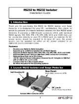
Installing the CPU and UART Modules (Desktop)
Step 7: Connect the Intellio C320Turbo/PCI Control Board to the CPU Module
with the shipped DB25 to DB25 cable as shown in the following picture.
If range extension or external power is required, please use 10-signal-pin
cable coming with long range extension kit, instead. Thus, there are two
types of installation: without power adapter and with power adapter,
which are described as follows:

Hardware Installation
Intellio C320Turbo/PCI User's Manual 2-3
Without power adapter (for normal condition)
In most cases, you need not a power adapter.
A: Set the CPU Module power switch to the OFF position. This is
absolutely necessary when installing or removing the cable, the CPU
Module or the UART Module(s). Power should not be switched on
until you installed all components.
B: Plug the DB25 male end of the shipped 2-meter 25-signal-pin cable
into the connector on the rear panel of the Intellio C320Turbo/PCI
Control Board. Refer to the chapter 5 for the cable pinout details.
2
3
4
5
6
7
8
1
2
3
4
5
6
7
8
1
25-signal-pin Cable
00
UART Module UART Module CPU Module
C320 Turbo/PCI
C: Plug the other DB25 female end into the CPU Module’s DB25
connector.
With
power
adapter
(for range extension/external power
condition)
In case of range extension or external power requirement, you need a
power adapter.
A: Set the CPU Module power switch to the OFF position. This is
absolutely necessary when installing or removing the cable, the CPU
Module or the UART Module(s). Power should not be switched on
until you installed all components.

2-4 Intellio C320Turbo/PCI User's Manual
B: Plug the DB25 male end of the shipped 2-meter 10-signal-pin cable
(the link cable comes with long range extension kit or the one
fabricated according to the pinouts in the chapter 5) into the connector
on the rear panel of the Intellio C320Turbo /PCI Control Board.
2
3
4
5
6
7
8
1
2
3
4
5
6
7
8
1
00
Power Adapter
UART Module
UART Module
CPU Module
10-signal-pin
Cable
C320 Tur bo/PCI
C: Plug the other DB25 female end into the CPU Module’s DB25
connector.
Warning! Do not use a 25-signal-pin cable to connect the
Intellio C320Turbo /PCI Control Board to the CPU
Module when using the power adapter as this will
cause power crash. (One power comes from the
power adapter while the other power comes from the
Intellio C320Turbo /PCI Control Board.)
D: Connect the power adapter to the CPU Module. Keep the CPU
Module’s power switch in the OFF position. If UART Module(s) is
(are) also required, keep the CPU Module’s power switch in the OFF
position until all necessary UART Module(s) is (are) installed.
E: Install the power adapter to a power source, either 110V or 220V AC.
Adjustment to the AC power specs is done automatically.

Hardware Installation
Intellio C320Turbo/PCI User's Manual 2-5
Step 8: Connect the first UART Module to the CPU Module. Connect the second
UART Module to the first one if necessary and so on.
For better fixation of modules, Fixing Kit is available and see the bottom
view of modules below to install.
Step 9: After making sure that each component has been correctly installed, you
are recommended to power on the CPU Module first and then power on
the PC system secondly.
☞
☞☞
☞ Now the installation of the external CPU/UART modules is complete.
Continue to install the software driver explained in the chapter 3.
Installing the Basic and Extensive Modules (Rackmount)
Step 7: Connect the Intellio C320Turbo/PCI Control Board to the Basic Module
with the shipped DB25 to DB25 cable as shown in the following picture.
If range extension or external power is required, please use 10-signal-pin
cable coming with long range extension kit, instead. Thus, there are two
types installation: without power adapter and with power adapter,
which are described as follows:
To Control Board
CPU Module
UART Module
UART Module
ScrewsMetal Plate

2-6 Intellio C320Turbo/PCI User's Manual
Without power adapter (for normal condition)
In most cases, you need not a power adapter.
Extensive Module
Basic Module
25-singal-pin Cable
C320 Tur bo/PCI
A: Set the Basic Module power switch to the OFF position. This is
absolutely necessary when installing or removing the cable, the Basic
Module or the Extensive Module(s). Power should not be switched on
until you installed all components.
B: Plug the DB25 male end of the shipped 2-meter 25-signal-pin cable
into the connector on the rear panel of the Intellio C320Turbo/PCI
Control Board. Refer to the chapter 5 for the cable pinout details.
C: Plug the other DB25 female end into the Basic Module’s DB25
connector.
With power adapter (
for range extension/external power condition
)
In case of range extension or external power requirement, you need a
power adapter.
A: Set the Basic Module power switch to the OFF position. This is
absolutely necessary when installing or removing the cable, the Basic
Module or the Extensive Module(s). Power should not be switched on
until you installed all components.
B: Plug the DB25 male end of the shipped 2-meter 10-signal-pin cable
(the link cable comes with long range extension kit or the one
fabricated according to the pinouts in chapter 5) into the connector on
the rear panel of the Intellio C320Turbo/PCI Control Board.

Hardware Installation
Intellio C320Turbo/PCI User's Manual 2-7
10-singal-pin Cable
Power Adapter
Extensive Module
Basic Module
C320 Turbo/PCI
C: Plug the other DB25 female end into the Basic Module’s DB25
connector.
Warning! Do not use a 25-signal-pin cable to connect the
Intellio C320Turbo/PCI Control Board to the
Basic Module when using the power adapter as this
will cause power crash. (One power comes from the
power adapter while the other power comes from
the Intellio C320Turbo/PCI Control Board)
D: Connect the power adapter to the Basic Module. Keep the Basic
Module’s power switch in the OFF position. If Extensive Module(s)
is(are) also required, keep the Basic Module’s power switch in the
OFF position until all necessary Extensive Module(s) is (are)
installed.
E: Install the power adapter to a power source, either 110V or 220V AC.
Adjustment to the AC power specs is done automatically.
Step 8: If one more Extensive Module is required, plug the DB37 to DB37 male
end of the shipped 1-meter cable into the DB37 female connector on the
rear panel of the Basic Module and the other end of the cable into the
DB37 male connector on the rear panel of the Extensive Module. If more
Extensive Module is needed, connect the next Extensive Module to the
previous one as described above.

2-8 Intellio C320Turbo/PCI User's Manual
To mount the module(s) on the industrial standard 19” rack, Rack Mount
Kit, including two L-type plates and eight screws, should be applied.
Multi
p
ort Controller with Rack Mount Kit installed
(
Front View
)
L-type Plate
L-type Plate
Multiport Controller
BA
S
I
C
M
O
DULE
P
owe
r
TxD
R
xD
D
TR
D
SR
R
T
S
CT
S
D
CD
M
odule Channe
l
Step 9: After making sure that each component has been correctly installed, you
are recommended to power on the Basic Module first and then power on
the PC system secondly.
☞ Now the installation of the external Basic/Extensive module is complete.
Continue to install the software driver explained in chapter 3.
Operating LED Indicators
After completing the installation and powering on the CPU/Basic Module and the
PC system, check the two-digit LED display on the CPU/Basic Module. These LEDs
show the results of the system self-diagnostic tests, which are run by the CPU/Basic
Module after startup.
The CPU/Basic Module will first test the ROM and RAM of itself, and then
UART/Extensive Module(s) if present. If any error is found, the LED display will
show one of the messages described in “Troubleshooting” chapter.
Multiport Controller with Rack Mount Kit installed ( Rear View )
L-t
yp
e Plate
L-type Plate
Screw

Hardware Installation
Intellio C320Turbo/PCI User's Manual 2-9
If the first test passed, the CPU/Basic Module will then display “Ld” waiting for
loading firmware from the Intellio C320Turbo/PCI Control Board. After loading
the firmware, the CPU Module will scan for the number of UART Modules or the
number of ports available. The LED will show the last accessible port.
CPU Module
The left digit shows the UART Module number and the right digit shows the last
port number within a UART Module. The UART Module closest to the CPU
Module is of number 1. The next module is of number 2, and so on. For example, if
“48” is displayed, it means that the last accessible port is the eighth port of the fourth
UART Module.
Basic Module
The left digit shows the number of 8-port unit that configured (if continuous 8 ports
are considered as an 8-port unit) and the right digit shows the last port number
within an 8-port unit. For example, if “48” is displayed, it means that the last
accessible port is the eighth port of the fourth 8-port unit.
To see a particular port’s line status, you can keep pressing Module Button and
Channel (Port) Button till the desired port is shown on LED display, then look at the
seven indicators TxD, RxD, DTR, DSR, RTS, CTS, and DCD. This provides a
convenient diagnostic ways for Intellio C320Turbo/PCI. Normally, DTR and RTS
CPU Module
4
8
CHANNEL
MODULE
TRDDRCD
XXTSTTC
DDRRSSD
Multi
p
ort Controlle
r
B
asi
c
﹙
o
﹙
d
﹙
u
﹙
le
P
owe
r
TxD
R
xD
D
TR
D
SR
R
T
S
CTS
D
CD
M
odule Channel
Basic Module
48
M
/