

Retain This Manual In A Safe Place For Future Reference
American Dryer Corporation products embody advanced concepts in engineering, design, and safety. If
this product is properly maintained, it will provide many years of safe, efficient, and trouble-free operation.
Only qualified technicians should service this equipment.
Observe all safety precautions displayed on the equipment or specified in the installation manual included
with the dryer.
The following FOR YOUR SAFETY caution must be posted near the dryer in a prominent location.
We have tried to make this manual as complete as possible and hope you will find it useful. ADC reserves
the right to make changes from time to time, without notice or obligation, in prices, specifications, colors,
and material, and to change or discontinue models.
Important
For your convenience, log the following information:
DATE OF PURCHASE __________________________ MODEL NO. _______________________________________
RESELLERS NAME _______________________________________________________________________________
Serial Number(s) ________________________________________________________________________________
________________________________________________________________________________
________________________________________________________________________________
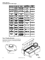
Replacement parts can be obtained from your reseller or the ADC factory. When ordering replacement parts
from the factory, you can FAX your order to ADC at (508) 678-9447 or telephone your order directly to the ADC
Parts Department at (508) 678-9000. Please specify the dryer model number and serial number in addition to
the description and part number, so that your order is processed accurately and promptly.
The illustrations on the following pages may not depict your particular dryer exactly. The illustrations are a
composite from the various dryer models. Be sure to check descriptions of the parts thoroughly before
ordering.
IMPORTANT NOTE TO PURCHASER
Information must be obtained from your local gas supplier on the
instructions to be followed if the user smells gas. These instructions
must be posted in a prominent location near the dryer.
FOR YOUR SAFETY
Do not store or use gasoline or other
flammable vapors or liquids in the
vicinity of this or any other appliance.
POUR VOTRE SÉCURITÉ
Ne pas entreposer ni utiliser
dessence ni dautres vapeurs ou
liquides inflammables dans le
voisinage de cet appareil ou de yout
autre appareil.

Important
You must disconnect and lockout the electric supply
and the gas supply or the steam supply before
any covers or guards are removed from the
machine to allow access for cleaning, adjusting,
installation, or testing of any equipment per OSHA
(Occupational Safety and Health Administration)
standards.
Please observe all safety precautions displayed
on the equipment and specified in the installation
manual included with the dryer.
For Your Safety
Do not store or use gasoline or other flammable
vapor and liquids in the vicinity of this or any other
appliance.
Do not dry mop heads in the dryer.do not use dryer
in the presence of dry cleaning fumes.
Caution
Dryers should never be left unattended while in
operation.
Warning
Children should not be allowed to play on or near
the dryers.
Children should be supervised if near dryer(s) in
operation.
The dryer must never be operated with any of the
back guards, outer tops, or service panels
removed. Personal injury or fire could result.
Dryer must never be operated without the lint filter
or screen in place, even if an external lint collection
system is used.
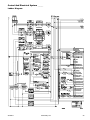
The wiring diagram for the dryer is located in the
front electrical control box area.
Table of Contents
Reference Guide (Front) ............................... 2
Reference Guide (Left Side) .......................... 3
Reference Guide (Right Side) ........................ 4
Reference Guide (Right Side) ........................ 5
Safety Precautions ........................................ 6
Routine Maintenance .................................... 7
Cleaning .................................................................. 7
Lubrication .............................................................. 7
Adjustments ........................................................... 8
Installation Requirements ............................ 8
Enclosure/Air Supply/Exhaust Requirements .......... 8
Electrical And Gas Requirements ............................ 8
Operational Service Check Procedure ..................... 9
Component Description/Replacement .......... 9
Gas Burner and Ignition System ............................. 9
Pilot Gas Supply Line ............................................ 11
Main Gas Supply Line ............................................ 11
Natural Gas and Liquid Propane (L.P.) Gas
Conversion Instructions ......................................... 15
Steam Heat System .............................................. 15
Tilting System Description .................................... 17
Air Jet System ...................................................... 20
Blower (Squirrel Cage Fan) Motor Assembly ......... 21
Blower (Squirrel Cage Fan)
Electrical Components .......................................... 23
Filter/Regulator Assembly ..................................... 24
Compressed Air System ....................................... 25
Door Systems ....................................................... 26
Control and Electrical System ............................... 29
Basket (Tumbler) System ..................................... 35
Safety Devices ...................................................... 39
Top of Tumbler (Basket) ........................................ 40
Phase 7 Non-Coin System Diagnostics ....... 41
Diagnostic L.E.D. Display Fault Messages ........... 41
Input/Output (I/O) Board L.E.D. Indicators ............. 41
Troubleshooting and Replacement ............. 44
Procedure for Functional Check of
Replacement Components ......................... 47
Sensor Activated Fire Extinguishing
(S.A.F.E.) System .......................................... 47

2 American Dryer Corp. 450260-1
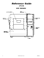
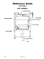
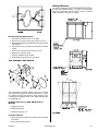
Reference Guide
(Front)

450260-1 www.amdry.com 3
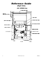
Reference Guide
(Left Side)

4 American Dryer Corp. 450260-1
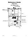
Reference Guide
(Right Side)

450260-1 www.amdry.com 5
Reference Guide
(Right Side)

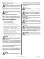
6 American Dryer Corp. 450260-1
SAFETY PRECAUTIONS __________
Warning
For your safety, the information in this manual must
be followed to minimize the risk of fire or explosion
or to prevent property damage, personal injury, or
loss of life.
The dryer must never be operated with any of the back guards,
outer tops, or service panels removed. Personal injury or fire
could result.
Caution
The dryer should never be left unattended while in
operation.
Do not store or use gasoline or other flammable vapors and
liquids in the vicinity of this or any other appliance.
Purchaser/user should consult the local gas supplier for
proper instructions to be followed in the event the user smells
gas. The instructions should be posted in a prominent
location.
What To Do If You Smell Gas ________
Do not try to light any appliance.
Do not touch any electrical switch.
Do not use any phone in your building.
Clear the room, building, or area of all occupants.
Immediately call your gas supplier from a neighbors
phone. Follow the gas suppliers instructions.
If you cannot reach your gas supplier, call the fire
department.
Installation and service must be performed by a qualified
installer, service agency, or gas supplier.
Dryer(s) must be exhausted to the outdoors.
Although ADC produces a very versatile dryer, there are
some articles that, due to fabric composition or cleaning
method, should not be dried in it.
Warning
Dry only water washed fabrics. Do not dry articles
spotted or washed in dry cleaning solvents, a
combustible detergent, or All Purpose cleaner.
Explosion could result.
Do not dry rags or articles coated or contaminated with
gasoline, kerosene, oil, paint, or wax. Explosion could result.
Do not dry mop heads. Contamination by wax or flammable
solvents will create a fire hazard.
Do not use heat for drying articles that contain plastic, foam,
sponge rubber, or similarly textured rubberlike materials.
Drying in a heated basket (tumbler) may damage plastics or
rubber and also may be a fire hazard.
A program should be established for the inspection and
cleaning of lint in the burner area, exhaust ductwork, and
area around the back of the dryer. The frequency of inspection
and cleaning can best be determined from experience at
each location.
Warning
The collection of lint in the burner area and exhaust
ductwork can create a potential fire hazard.
For personal safety, the dryer must be electrically grounded
in accordance with local codes and/or the National Electrical
Code ANSI/NFPA NO. 70-LATEST EDITION or in Canada, the
Canadian Electrical Codes Parts 1 & 2 CSA C22.1-1990 or
LATEST EDITION.
Note
Failure to electrically ground the dryer properly will
void the warranty.
Under no circumstances should the dryer door switches, lint
drawer switch, or heat safety circuit, ever be disabled.
Warning
Personal injury or fire could result should the dryer
door switches, lint drawer switch, or heat safety circuit,
ever be disabled.
This dryer is not to be used in the presence of dry cleaning
solvents or fumes.
Remove articles from the dryer as soon as the drying cycle
has been completed.
Warning
Articles left in the dryer after the drying and cooling
cycles have been completed can create a fire
hazard.
Read and follow all caution and direction labels attached to
the dryer.
Warning
YOU MUST DISCONNECT AND LOCKOUT THE
ELECTRIC SUPPLY AND THE GAS SUPPLY OR
THE STEAM SUPPLY BEFORE ANY COVERS OR
GUARDS ARE REMOVED FROM THE MACHINE TO ALLOW
ACCESS FOR CLEANING, ADJUSTING, INSTALLATION, OR
TESTING OF ANY EQUIPMENT PER OSHA (Occupational
Safety and Health Administration) STANDARDS.
Important
Label all wires prior to disconnection when servicing
the microprocessor controller (computer) and the
ignition module. Wiring errors can cause improper
and dangerous operation.
!
!
!
!
!
!
!
!
!

450260-1 www.amdry.com 7
ROUTINE MAINTENANCE _________
Cleaning ______________________________
A schedule should be established for periodic inspection,
cleaning, and removal of lint from various areas of the dryer,
as well as throughout the ductwork system. The frequency of
cleaning can best be determined from experience at each
location. Maximum operating efficiency is dependent upon
proper air circulation. The accumulation of lint can restrict
this airflow. If the guidelines in this section are met, an ADC
dryer will provide many years of efficient, trouble-free, and
most importantly safe operation.
Warning
Lint from most fabrics is highly combustible. The
accumulation of lint can create a potential fire
hazard.
Keep dryer area clear and free from combustible materials,
gasoline, and other flammable vapors and liquids.
Note
Remove power from the dryer before performing any
maintenance on the dryer.
Suggested time intervals shown are for average usage which
is considered six (6) to eight (8) operational (running) hours
per day.
Suggested Cleaning Schedule
Every Third or Fourth Load
Clean the lint screen. A clogged lint screen will cause poor
dryer performance. The lint screen is located in the lint drawer
in the base of the dryer. Pull out the lint drawer, brush the lint
off the lint screen, and remove the lint. Inspect the lint screen
and replace if torn.
Clean the lint screen from the power burner booster fan
located on the right side panel.
Note
The frequency of cleaning the lint screens can best
be determined from experience at each location.
Weekly
Remove the panels on each side of the basket (tumbler)
section and remove any lint accumulation from the basket
(tumbler) drive motor, drive shafts, gear reducer, drive belts,
drive wheels, and drive shaft bearings.
Warning
To avoid the hazard of electrical shock, discontinue
electrical supply to the dryer.
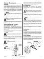
Monthly
Empty the compressed air filter
bowl.
Note
Regulator pressure is to
be set at 80 psi
(5.51 bar).
Clean any lint accumulation from the gas valve and burner
area at the top of the dryer, the fan (impellor) motor, and the
fan (impellor) bearings located in the dryer base.
Every 6 Months
Steam Models - Clean the steam coil fins. We suggest
using compressed air and a vacuum cleaner with brush
attachment.
Note
When cleaning steam coil fins, be careful not to bend
the fins. If fins are bent, straighten by using a fin
comb, which is available from any local air
conditioning supply house.
Inspect and remove any lint accumulation in customer
furnished exhaust ductwork system and from the dryers
internal exhaust ducting.
Note
The accumulation of lint in the exhaust ductwork can
create a potential fire hazard.
Do not obstruct the flow of combustion and
ventilation air. Check customer furnished back draft dampers
in the exhaust ductwork. Inspect and remove any lint
accumulation, which can cause the damper to bind or stick.
When cleaning the dryer cabinet(s), avoid using harsh
abrasives. A product intended for the cleaning of appliances
is recommended.
Clean off any lint accumulation on top of the temperature
probe and the hi-limit switch located above the lint basket.
Lubrication ___________________________
Monthly
The two (2) bearings that support the impellor/fan shaft must
be lubricated. Use Shell Alvania #2 grease or its equivalent.
Generically, this grease would be described as a NLGI Grade
2 multipurpose industrial grease with a lithium thickener and
mineral base oil.
Every 3 Months
The four (4) bearings that support the drive and idler shafts
must be lubricated. Use Shell Alvania #2 grease or its
equivalent. Generically, this grease would be described as a
NLGI Grade 2 multipurpose industrial grease with a lithium
thickener and mineral base oil.
!
!
!
!
!
!
!

8 American Dryer Corp. 450260-1
INSTALLATION REQUIREMENTS ____
Installation should be performed by competent technicians
in accordance with local and state codes. In the absence of
these codes, the installation must conform to applicable
American National Standards: ANSI Z223.1-LATEST EDITION
(National Fuel Gas Code) or ANSI/NFPA NO. 70-LATEST
EDITION (National Electrical Code) or in Canada, the
installation must conform to applicable Canadian Standards:
CAN/CGA-B149.1-M91 (Natural Gas) or CAN/CGA-B149.2-
M91 (Liquid Propane [L.P.] Gas) or LATEST EDITION (for
General Installation and Gas Plumbing) or Canadian
Electrical Codes Parts 1 & 2 CSA C22.1-1990 or LATEST
EDITION (for Electrical Connections).
Enclosure/Air Supply/Exhaust
Requirements ________________________
Note
The following information is very brief and general.
For a detailed description, refer to the installation
manual included with the dryer.
Bulkheads and partitions around the dryer should be made
of noncombustible materials. Allowances should be made
for the opening and closing of the control door and lint door.
Also, allowances should be made in the rear for ease of
maintenance. (Refer to the installation manual for
recommended distances and minimum allowances
required.)
When the dryer is operating, it draws in room air, heats it,
passes this air through the basket (tumbler), and exhausts it
out of the building. Therefore, the room air must be continually
replenished from the outdoors. If the make-up air is
inadequate, drying time and drying efficiency will be adversely
affected. Ignition problems and sail switch fluttering
problems on gas dryers may result, and you also could have
premature motor failure from overheating. The air supply
must be given careful consideration to ensure proper
performance of each dryer.
Important
Make-up air must be provided from a source free of
dry cleaning fumes. Make-up air that is
contaminated by dry cleaning fumes will result in
irreparable damage to the motors and other dryer
components.
Exhaust ductwork should be designed and installed by a
competent technician. Improperly sized ductwork will create
excessive back pressure which will result in slow drying,
increased use of energy, and shutdown of the burner by the
airflow (sail) switch, burner hi-limit, or lint chamber hi-heat
protector thermostat. (Refer to the installation manual for
more details.)
Caution
Improperly sized or installed exhaust ductwork can
create a potential fire hazard.
Electrical and Gas Requirements ___
It is your responsibility to have all electrical connections made
by a properly licensed and competent electrician to ensure
that the electrical installation is adequate and conforms to
local and state regulations or codes. In the absence of such
codes, all electrical connections, materials, and
workmanship must conform to the applicable requirements
of the National Electrical Code ANSI/NFPA NO. 70-LATEST
EDITION, or in Canada, the Canadian Electrical Codes Parts
1 & 2 CSA C22.1-1990 or LATEST EDITION.
!
!
!
Every 6 Months
Change gear oil in basket (tumbler) shaft gear reducer.
Remove the drain plug (located at the bottom rear of the
reducer).
After oil is completely drained, replace the drain plug.
Remove the vent plug and pour in 1.48 quarts (1.4 liters)
of Mobil Oil DTE HH5G (I.S.O. viscosity grade 460), SAE
90, or its equivalent.
Adjustments _________________________
7 Days After Installation and Every 6
Months Thereafter
Inspect bolts, nuts, screws, setscrews, nonpermanent gas
connections (unions, shutoff valves, orifices), and grounding
connections. Fan (impellor) V-belts, along with the motor
and drive belts should be examined and replaced if
necessary. Tighten loose V-belts when necessary. Complete
operational check of controls and valves. Complete
operational check of all safety devices (door switches, lint
drawer switch, sail switch, burner, and hi-limit thermostats).

450260-1 www.amdry.com 9
COMPONENT DESCRIPTION/
REPLACEMENT _________________
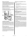
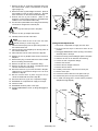
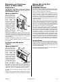
Gas Burner and Ignition System ____
The dryer's gas burner system operates on an On or Off
gas rate sequences to accurately control the tumblers
(basket's) drying temperature. Maximum firing rate is 2.8
million Btu/hr.
Upon a call from heat, the dryer computer sends a 120 volt
signal to the burner controller module (BCM) which initiates
and controls the ignition sequences. The BCM insures that
all the safety switches are closed before turning on the
combustion air burner fan, then checks to ensure that the
burner fan air switch has closed. The pilot gas flame is then
established, the flame rod, (which sits in this pilot flame),
comes in contact with the flame and signals the BCM. The
main motorized gas valves open in sequence, and full
operational flame is achieved.
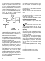
The BCM has five (5) light emitting diodes (L.E.D.) on its
cover and two (2) neons on the mounting base for ease of
troubleshooting, as well as dip switches inside for ease of
programming.
!
MAN2374
!
!
Important
Failure to comply with these codes or ordinances
and/or the requirements stipulated in this manual
can result in personal injury or component failure.
The dryer installation must meet the American National
Standard, National Fuel Gas Code ANSI Z223.1-LATEST
EDITION, or in Canada, the Canadian Electrical Codes Parts
1 & 2 CSA C22.1-1990 or LATEST EDITION (for Electrical
Connections) as well as, local codes and ordinances, and
must be done by a qualified technician.
Note
Undersized gas piping will result in ignition problems
and slow drying and can create a safety hazard.
The dryer must be connected to the type of gas (natural or
liquid propane [L.P.]) indicated on the dryer data label. If this
information does not agree with the type of gas available,
contact the reseller who sold the dryer or contact the factory.
The gas input ratings shown on the dryer data label are for
elevations up to 2,000 feet (609.6 meters), unless elevation
requirements of over 2,000 feet (609.6 meters) were specified
at the time the dryer order was placed with the factory. The
adjustment for dryers in the field for elevations over 2,000
feet (609.9 meters) is made by changing the burner orifices.
If this adjustment is necessary, contact the reseller who sold
the dryer or contact the factory.
Note
Any burner changes must be made by a qualified
technician.
Operational Service Check
Procedure ____________________________
After performing any service or maintenance function, an
operational check should be performed to ensure that all
components are performing properly.
Make a complete operational check of all the operating
controls to ensure that the timing is correct, temperature
selection switches are functioning properly.
Make a complete operational check of all safety related
circuits, door switches, hi-limit thermostat, sail switch, cycling
thermostats, etc.
The BCM controls all of the gas burner ignition components,
except for the motorized gas valve. When the drying set point
temperature is reached, the dryers computer closes the top
motorized gas valve, shutting off full flame.
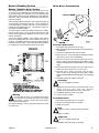
Major Burner Components
Burner Controller Module (BCM)
The BCM provides effective burner flame safeguard
control through adjustable purge and trial-for-ignition
timing. The BCM insures that all dryer safety switch
circuits are closed, delays ignition to allow the
combustion chamber to vent, and insures that a healthy
pilot flame is established before opening the main gas
valves. Five (5) L.E.D.s on the cover of the BCM allow for
easy troubleshooting. Dip switches on the back of the
module allow for easy programming.
Dip Switches Selections
Loosen the two (2) screws on the burner control module
cover and pull the module cover off of its base. The dip
switches are on the back of the cover.
Switch #1 - Recycling Mode
With this switch in the ON position, the burner will
recycle the ignition sequence once during each drying
cycle after a burner fan air switch or main flame failure,
but only if the failure occurs more than 35-seconds after
ignition. If this switch is OFF," the burner will lock out at
once.
Switch #2 - Intermittent Pilot
This switch is ON for intermittent pilot or OFF for
interrupted pilot. The dryer utilizes interupted pilot so
that the pilot flame doesnt stay lit during the entire drying
cycle. With interrupted pilot, the pilot flame goes out
once the main flame is established.
Switch #3 - Trial for Ignition (TFI) Time
When this switch is ON a Trial for Ignition (TFI) of ten
(10) seconds is set. If it is in the OFF position, the TFI
is five (5) seconds. The Trial for Ignition Time is the
length of time that the pilot is given to light. A ten (10)
second TFI is best for the dryer.
Switch #4, Switch #5, Switch #6, Switch #7- Purge Time
Switch #8 is for post purge selection. With switch #8 in
the "ON" position, the post purge time will be
15-seconds. When switch #4, switch #5, switch #6, and
switch #7 are in the OFF position, the post purge time
will be 0-seconds.

10 American Dryer Corp. 450260-1
Light Emitting Diode (L.E.D.) and Neon
Displays of the BCM (Burner Controller
Module)
Operating Interlock - L.E.D. is lit when:
All safety interlock switches are closed, applying a
110 VAC signal to terminal #7 of the burner controller
module (BCM).
Operating Interlock - L.E.D. is not lit when:
One (1) or more safety interlock switches (burner doors,
load door, optional unload door, gas pressure, lint
pressure, hi-temp alarm contacts, tumbler [basket]
stopped, and lint drawer) are open. If any of the safety
interlocks switches are open the burner ignition sequence
will not be attempted.
Air Failure - L.E.D. is lit if:
Burner fan air switch is not closed within 10 seconds of
start-up of blower
Burner fan air switch is open during firing cycle.
System Unsafe - L.E.D. is lit if:
A loose connection on the flame rod or spark plug.
All purge time dip switches are in the off position.
Flame is detected out of sequence.
Inductance is detected on sensor wires.
Wiring fault on terminals #3, #4, and #5.
An internal controller failure.
Air switch closed before start-up.
Flame Signal - L.E.D. is lit when:
The flame rod is in contact with the pilot flame and the
BCM converts a microampere (microamp) current
between the flame rod and ground into a three (3) 11 volt
DC signal that can be measured on the BCM. Inset one
(1) probe of a DC volt Meter into the flame signal port and
put the other probe to ground. The meter will read out the
three (3) 11 volt DC flame signal. If the flame signal
L.E.D. flickers on and off, this is a result of a weak flame
signal which can be caused by an intermittent wiring
connection between the flame rod and BCM, a faulty
ground connection, bad ground of the dryer, weak pilot
flame or dirty or defective flame rod.
Burner Controller Power On Indicator - Neon is lit when:
Burner Controller has its supply voltage of 120 VAC.
Burner for Air Switch Status Indicator - Neon is lit when:
Air switch is closed after start-up of blower (fan) and
interlocks are all closed.
Burner Fan Air Switch Status Indicator - Neon is not lit:
Air switch is not closed after start-up of burner fan.
Door interlocks are open.
A Combustion burner screen is clogged.
A door on the dryer is open.
Test/Reset Button
When this button is pushed in, the BCM will halt the
ignition sequence, once the pilot flame is established.
This allows the pilot flame to be adjusted.
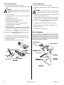
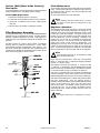
Flame Rod and Spark Plug
The pilot flame is lit by the spark plug, while flame sensing is
done through the flame rod. The spark plug is energized
when the pilot solenoid slave opens, igniting the pilot flame.
The pilot flame rod sits in the pilot flame and sends a 3 volt DC
to 11 volt DC signal to the BCM when it is in contact with the
pilot flame. The pilot flame should be about the size of a 3-
inch diameter ball and should heat the pilot flame rod so it is
red hot. When the main gas valve is turned on the flame
sensing will switch to main flame rod to confirm carry over to
the end of the burner.
Burner Fan System
The burner fan provides additional combustion air for proper
gas combustion. The fan provides approximately 900 cfm of
air in this burner box. The airflow is obtained when the air
pressure is measured at the air pressure tap on the gas burner
box approximately 1.25-inches water (3.1 millibars). The
combustion air system is comprised of the components
described on page 11 and page 12.

450260-1 www.amdry.com 11
Burner Fan Air Switch
The differential in air pressure is measured by the burner fan
air switch, which is located next to the burner fan motor. If the
combustion air is inadequate, this switch will prevent ignition.
The setting of this switch is adjustable, and it should be set
at approximately 0.59-inches (15 mm) of water column (W.C.)
because of slight variances in spring tension characteristics,
range settings, and markings are nominal.
Burner Fan and Motor
The combustion air is produced by a 6-1/4" squirrel cage fan
attached to a 1-1/2 hp, 3,600 rpm motor. The motor must
spin counterclockwise (CCW) as viewed from the rear of the
motor.
Combustion Air Lint Filter
The combustion air lint filter is made of a fine mesh stainless
steel screen which must be cleaned regularly. This screen
prevents any lint from entering the burner box.
Combustion Air Damper
To produce the required combustion airflow, this damper can
be adjusted. Remove the screen to get access to the damper.
Moving the damper closer to the blower inlet opening will
reduce the combustion airflow, and moving it away from the
blower inlet opening will increase the airflow. To measure
the combustion airflow, attached a manometer to the air
pressure tap on the burner box. The air pressure should
measure 1.25- inches (31.75 mm) to 1.5-inches (38.1 mm)
W.C.
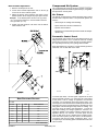
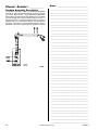
Pilot Gas Supply Line ________________
The pilot gas supply line consists of a manual shutoff valve,
pressure regulator, electric solenoid valve, back-loaded
pressure regulator, and an adjustable gas cock.
The gas pressure in this line should be approximately
3.5-inches (88.9 mm) W.C. for natural gas and 1.5-inches
(38.1 mm) W.C. for liquid propane (L.P.) gas. This will provide
a bushy pilot flame, which produces a signal through the
flame rod that is converted to 3 to 11 volts DC in the burner
controller module (BMC).
This flame can be adjusted in two (2)
ways
Pilot Inlet Pressure Regulator
Remove the cap and turn the slotted adjustment screw
clockwise (CW) for more gas and counterclockwise
(CCW) for less gas.
Adjustable Pilot Gas Cock
Remove the cap and turn the slotted adjustment screw
clockwise (CW) for less gas and counterclockwise (CCW)
for more gas.
The pilot line contains a back-loaded pressure regulator with
an impulse line connected to the gas burner inlet. The
regulator will maintain a constant pilot supply pressure in
the burner due to an increase in temperature. Do not adjust
this regulator.
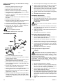
Main Gas Supply Line ________________
The main gas supply line consists of a pressure regulator,
two (2) motorized shutoff valves, HI/LO gas pressure switch,
manual shutoff valve.
The gas pressure at the burner should be 2.5-inches
(63.5 mm) W.C. for natural gas and 1.25-inches (31.8 mm)
water column for L.P. gas. This pressure is measured by a
manometer at the manual shutoff valve just top motorized
valve.
Motorized Gas Valve
The two (2) 2-inch F.P.T. motorized valve are ON/OFF gas
flow control valves. The valves motors operate on 120 VAC
and are electrically cascaded so that upper valve will not
open until lower valve has fully opened. A limit switch inside
the lower motorized valve provides the signal that the valve is
fully opened. These valves will open only when the BCM is
receiving a signal from the flame rod proving that the pilot
flame is established. The bypass of the second valve allows
for the low fire.
Top Motorized Gas Valve
The valve sets the gas rate of 2,800,000 Btu/hr (705,290
kcal/hr). To achieve this rate, the gas pressure must be set
for 2.5-inches (63.5 mm) water column for natural gas and
1.25-inches (31.8 mm) W.C. for L.P. gas. To adjust. loosen
the pan head screw located on the front of the top motorized
valve, while holding the valve body, turn the flow adjustment
clockwise (CW) for less gas and counterclockwise (CCW)
for more gas. Retighten the pan head screw when correct
gas flow is achieved. There is a switch located on the back of
the top gas valve that verifies valve closure. The BCM will go
into a system unsafe error and the burner will not begin a
burner sequence.

12 American Dryer Corp. 450260-1
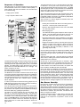
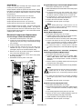
Sequence of Operation
With dryer power on, a 120 volt signal is sent to terminal #1
and terminal #2 of the burner controller module (BCM). A
power indicator light has been added to the controller base
for troubleshooting.
Drying cycle is started
Dryer computer calls for heat.
The BCM checks that all of the dryers safety circuits are closed
(terminal #7 of the BCM). If this is the case, then the green
operating interlocks light emitting diode (L.E.D.) on the BCM
will light. If a safety switch is open, the green L.E.D. will not
light, and the red SYSTEM UNSAFE L.E.D. will light. The
ignition sequence will stop.
If all safety switches are closed, the BCM will start the burner
fan motor (BCM terminal #8).
The BCM waits 10-seconds to allow the blower motor to get
up to speed, and then checks that the burner fan combustion
air switch (BCM terminal #6) circuit is closed. If this circuit is
open during the drying cycle, the Air Failure L.E.D. will light.
The gas valve will close, and a HEATER FAULT message
will be displayed.
In order to prevent this air switch from being jumped out, the
BCM checks to insure that this circuit is open prior to start-up,
then SYSTEM UNSAFE L.E.D. will light.
If the air flow switch closes after the burner fan is turned on,
the pilot solenoid valve (BCM terminal #3) is opened for ten
(10) seconds, and a spark is produced (BCM terminal #4) by
the burner spark plug, igniting the pilot flame.
The flame rod, which extends into the pilot flame, has
300 VAC on it from the BCM (terminal #S1). The flame lets
the current flow from the flame rod to ground, which is then
converted to 3 to 11 volts DC by the BCM. The flame signal
L.E.D. on the BCM lights up. Once the call for heat opens the
main valve, the flame rod circuit is switched to the opposite
side of the burner to confirm that the flame is across the
entire burner.
The spark plug will turn off 1.5-seconds after the pilot flame
is detected. If the pilot flame should fail during the
10-seconds period that the pilot solenoid is open. The BCM
will reenergize the spark. If the pilot flame is not established
at the end of this 10-second period, the system will lock out
and the FLAME FAILURE L.E.D. will light.
The 10-second period when the pilot solenoid opens and a
spark is produced is called the trial-for-ignition (TFI) time. It
is selected at either 5-seconds or 10-seconds by a dip switch
located on the back cover of the BCM.
The 3 volt DC to 11 volt DC signal from the flame rod to the
BCM can be measured by:
Closing the manual shutoff valve in the main gas line to
the burner. Leave the pilot manual valve open.
Push the Test and Reset button on the cover of the BCM
in to the test position.
Start a drying cycle
The BCM will halt the ignition sequence after the pilot is
ignited. The pilot flame should be about the size of a
tennis ball and should make the flame cord red hot.
Insert the positive probe of a DC Volt Meter in to the flame
signal port on the cover of the BCM. Connect the negative
probe to ground.
If signal is less than 3 volts DC, then the pilot may be too
small or too large, there may be a wiring connection
between the flame rod and BCM, the flame rod may be
dirty, (wash it with soap and water) or defective, or the
grounding may be faulty.
Once the flame probe signal is detected by the BCM, it waits
5-seconds to allow the pilot to stabilize and then opens the
main motorized gas valves (terminal #5 on the BCM) in
sequence.
The lower valve opens first. Upon full opening, its external
switch closes, enabling the second motorized valve to open
and full flame to be achieved.
At this time an 8-second delay timer is activated. After
8-seconds the flame sensor is switched from the pilot to the
main flame sensor on the opposite side of the burner box.
If flame failure occurs within 35-seconds, the system will
lock out and the FLAME FAILURE pilot will light.
Once main flame is established, the burner will remain in
the full fire mode until the drying set point temperature has
been reached. At this point, the dryer computer will cycle the
top motorized gas valve closed the position. The OFF mode
will be maintained until the dryers temperature falls below
the drying set point temperature. The motorized valve will
then be returned to the full fire position. The ON/OFF motor of
the motorized valve, it moves to the full fire position. OFF is
achieved when no voltage is applied to the motorized valve.
Gas Burner Start-Up
New gas lines are filled with air and must be purged before
the burner will light. To do this close the upper manual
shutoff valve, but leave the pilot line shutoff open. Push in the
test and reset button on the cover of the BCM. This will freeze
the ignition sequence when the pilot flame ignites. This
allows time to examine the pilot flame, and measure the
flame rod signal to the BCM.
Connect a pressure gauge or water tube to the pilot gas
pressure tap. Start the dryer. Follow the ignition process by
referring to the Sequence of Operation section of this
manual.
MAN7174

450260-1 www.amdry.com 13
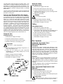
Burner Air Switch
The dryer uses a burner air switch on its burner components.
The differential air pressure is measured by this air switch,
which is located next to the burner fan motor. If the combustion
air is inadequate, this switch will prevent ignition. The setting
of this burner air switch is adjustable, and is preset at the
factory.
When the pilot flame is ignited, the pilot gas pressure should
measure 3.5-inches (38.1 mm) water column (W.C.) for
natural gas and 1.5-inches (88.9 mm) W.C. for liquid propane
(L.P.) gas. The pilot flame should be about the size of a
3-inch diameter ball.
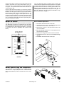
Once the pilot has been properly set, remove the pressure
gauge from the pilot line connect a differential pressure gauge
between the main gas pressure tap (HI port) and the air
pressure tap (LO port) on the side of the gas burner box. The
lines connecting the gauge to these taps must be long
enough to allow the gauge to sit outside of the dryer so that
the burner section access door can be closed when the dryer
runs. Running the dryer with these doors open will give an
incorrect air pressure reading.
MAN4398
Once this differential gauge is installed, open the main gas
shutoff valve and push the test and reset button on the BCM
so that the button springs out. Restart the dryer. The ignition
process should now continue to the full gas flow state. The
differential gauge should read 2.5-inches (63.5 mm) W.C. for
natural gas and 1.25-inches (31.8 mm) W.C. for L.P. gas. If it
does not, adjust the top gas valve as described in Top
Motorized Gas Valve on page 11.
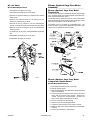
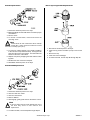
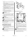
Burner Air Switch Replacement
1. Discontinue electrical service to the dryer.
2. Remove the two (2) 1/4" x 1/8" M.P.T. straight brass
connectors from the burner fan air switch.
3. Remove the 5/16-18 x 3/4" tap bolt as well as the
5/16" lock washer.
4. Mark and identify the wires for correct replacement on
the new burner air switch.
5. Remove the cord grip from the burner fan air switch.
6. To install new burner air switch, reverse Step #5 through
Step #2.
7. Reestablish electrical service to the dryer.
Burner Squirrel Cage Fan Components
The combustion air is produced by a 6-1/4" squirrel cage fan,
attached to a 1-1/2 hp, 3,600 rpm motor. This motor must
spin counterclockwise (CCW) as viewed from the rear of the
motor.

14 American Dryer Corp. 450260-1
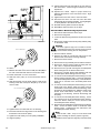
Burner Fan Motor
Burner Fan Motor Replacement
1. Discontinue electrical service to the dryer.
2. Remove the four (4) #8-18 x 7/16" TEK screws which
secure the inlet ring to the combustion air blower
housing.
3. Remove the two (2) 1/2-20 left hand jam nuts as well as
the 1/2-inch flat washer.
4. Remove the 6-1/4" squirrel cage fan.
5. Remove the motor cover plate to reveal the wiring.
6. Mark and identify wiring for correct replacement on to
the new motor.
7. Remove the cord grip and wiring harness from the motor.
8. Remove the four (4) 3/8-16 x 3/4" hex head bolts securing
the motor to the combustion air blower housing.
9. To install new burner fan motor, reverse steps.
10. Reestablish electrical service to the dryer.
Burner Fan Squirrel Cage
Burner Fan Squirrel Cage Replacement
1. Discontinue electrical service to the dryer.
2. For removal of the 6-1/4" squirrel cage fan, follow Step
#2 through Step #4 of the Burner Fan Motor Replacement
instructions above.
3. For replacement of new 6-1/4" squirrel cage fan, reverse
Step #4 through Step #2 of the Burner Fan Motor
Replacement instructions.
4. Reestablish electrical service to the dryer.
Burner Fan Electrical Components
Burner Fan Thermal Magnetic Starter (TMS)
The TMS is used as a safety device to manually disconnect
the motor so that it will be protected from damage in the
event of a locked rotor condition. The overload has a dial
setting on the face of the device. To set the overload, refer to
the specific electrical diagram. The overload is specifically
designed for motor applications. It has a current curve built
into it so the initial high current draw by the motor will not trip
the overload. On the face of the overload are two (2) push-
buttons; "START" (Black or Tan) and "STOP" (Red - 0). The
overload has to be in the "START" mode for the motor to run.
Thermal Magnetic Starter (TMS) Replacement
1. Discontinue electrical service to the dryer.
2. Mark L1, L2, L3, and T1, T2, T3 on the wires to the TMS
for correct replacements.
3. Set the amp (amphere) rating on the TMS according to
the electrical schematic supplied with the dryer.
4. To remove the TMS, pull the tab on the bottom of the
TMS and lift upwards.
5. To install the new TMS, reverse Step #4 through Step
#2.
6. Reestablish electrical service to the dryer.
Auxiliary Contact Block
The auxiliary contact block is mounted on the side of the
overload. Its function is to sense an overload trip, thereby
triggering a safety fault which will disable the drying cycle.
Auxiliary Contact Block Replacement
1. Discontinue electrical service to the dryer.
2. Remove the TMS from the din rail by pulling the tab on
the bottom of the auxiliary contact block and lift upwards.
3. Remove the two (2) wires going to the auxiliary contact
block and label them for correct reinstallation.
4. There are two (2) types of auxiliary contact blocks: one
type has a screw and the other type has a clip. In either
type, disassembly and assembly is recommended with
the TMS in the stop position.
5. To install the new auxiliary contact block, reverse Step
#4 through Step #2.
6. Reestablish electrical service to the dryer.
Varistor (Metal Oxide Varistor [MOV])
The metal oxide varistor (MOV) is used to suppress any
inductive electrical spikes produced by the energizing and
collapsing of coil voltage.
Varistor (Metal Oxide Varistor [MOV]) Replacement
1. Discontinue electrical service to the dryer.
2. Loosen the screws marked A1 and A2 on the contactor.
3. Verify that no additional wires were inadvertently
removed.
4. To install the new metal oxide varistor (MOV), reverse
Step #3 through Step #1.
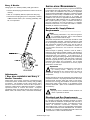
Burner Door Switch
The burner door switch is a part of the dryer's safety circuit. If
at any time during a drying cycle the burner doors are open,
the controller will shut the dryer down and display "FRONT
DOOR OPEN." (Verify that the burner door switches are not
out of adjustment.)
Burner Door Switch Adjustment
1. With burner doors closed, verify if PLC (Programmable
Logic Controller) Input #8 is ON or FDRC red light
emitting diode (L.E.D.) on control board is on.
2. If indicator shows that the door is open , then adjustment
is needed. Remove cover from the switch box.
Note
Adjust one switch at a time.
3. Adjust the switch until the magnet on the door activates
the switch.
4. Put the cover back and close the burner doors.
MAN7175
SC 04/1/04
!

450260-1 www.amdry.com 15
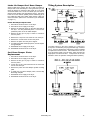
Heat Mode Air Flow
During a call for heat, solenoid S10 turns on and air first
enters the dryer on the bottom right side of the dryer. The air
then passes through the open inlet air damper, then passes
through the six (6) steam coils to heat the air. Next, the air
enters the tumbler (basket) heating the load inside. The air
then goes through the lint screen. Once the air is filtered by
the lint screen it is forced out of the exhaust by the blower. A
percentage of the air being exhausted gets reheated by the
heat reclaimer to be used again. (Refer to the Drying Cycle
illustration below).
Temperature Set Point/Cool Down Mode
During a cool down mode, solenoid S10 turns off and solenoid
S9 turns on. In this mode, the air enters through the cool
down damper on top of the dryer and enters the tumbler
(basket). The air then passes through the lint basket and
gets pushed out of the exhaust by the blower wheel. (Refer
to the Cool Down Cycle illustration below).
Natural Gas and Liquid Propane (L.P.)
Gas Conversion Instructions ________
Important
Conversion must be performed by competent
technicians in accordance with local and state
codes.
1. Loosen the screw on the high fire valve cap that doesnt
have the paint drop.
2. Turn the cap to the + to increase the pressure or to the
- to decrease the pressure.
3. Take the pressure reading at the outlet of the valve.
4. Tighten the screw to lock the cap once the pressure is
set to 1.25 inches of water column (W.C.) for L.P. gas.
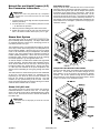
Steam Heat System _________________
The steam dryer uses six (6) steam coils to produce a heat
input of 60 Bhp (boiler horsepower). The dryer utilizes three
(3) separate dampers to direct air in the drying process or
cool down process of a cycle.
The first damper is the cool down damper located on the top
of the dryer, and is used to bring fresh, room temperature air
into the tumbler (basket). When the dryer is in the cool down
mode or has reached its set point temperature, the damper
will be in the open position further reducing increases in
tumbler (basket) temperature. When there is a call for heat,
the damper closes, thereby requiring all of the air entering
the tumbler (basket) to go through the steam coils.
An inlet air damper is located in the middle of the right hand
section of the dryer. During a call for heat, this damper opens,
which allows ambient air into the dryer, which then goes
through the steam coils, heating the air. During cool down,
or if the dryer has reached its set point temperature, the
damper closes eliminating air from going through the steam
coils.
The heat reclaimer is used to divert a portion of the exhausted
air and run it through the steam coil, reheating the air.
Depending on the stroke at which the heat reclaimer has
been set, the amount of reclaimed air will vary. The heat
reclaimer is only opened during a call for heat. Once the
dryers' set point temperature is reached or during a cool down
mode the heat reclaimer will be closed.
Steam Coil pH Level
The normal pH level for copper type steam coils must be
maintained between a value of 8.5 to 9.5. For steel type
steam coils the pH level must be maintained between a value
of 9.5 to 10.5. These limits are set to limit the acid attack of
the steam coils.
Important
Coil failure due to improper pH level will void the
warranty.
!
!

16 American Dryer Corp. 450260-1
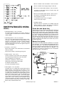
H
EAT
R
ECLAIMER
S
ETTINGS
Z = 1-5/8
Y+Z=X Y %HR Inches Reclaimed
1-1/8" 1/2" 7.46 1-1/4"
2-5/8" 1" 15.67 2-5/8"
3-1/8" 1-1/2" 25.37 4-1/4"
3-5/8" 2" 34.32 5-3/4"
4-1/8" 2-1/2" 43.28 7-1/4"
4-5/8" 3" 50.74 8-1/2"
5-1/8" 3-1/2" 58.95 9-7/8"
FULL OPEN 16-3/4"
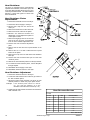
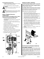
Heat Reclaimer
The dryer is equipped with a pneumatically
operated heat reclaimer, which when open, will
recirculate approximately fifteen percent (15%)
of the dryers' exhausted air. The heat reclaimer
damper is closed until ignition of flame has
been established.
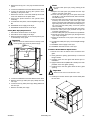
Heat Reclaimer Piston
Replacement
1. Discontinue electrical service to the dryer.
2. Discontinue the air supply to the dryer.
3. Remove the C-clip from one end of the
clevis pin.
4. Remove the setscrew from the clevis rod.
5. Remove the clevis rod from the piston.
6. Measure the distance between the
adjustment nut and adjustment plate for
correct piston stroke.
7. Remove the eight (8) 5/16-18 hex nuts as
well as the four (4) 5/16" lock washers
from the heat reclaimer adjustment rods.
8. Remove the heat reclaimer adjustment
plate.
9. Remove the air lines from the top and bottom of the
piston.
10. Remove the 1/4" x 1/4" M.P.T. elbow from the top and
bottom of the piston.
11. Remove the C-clip from one side of the heat reclaimer
base pin.
12. Remove the heat reclaimer base pin from the heat
reclaimer piston.
13. Remove the heat reclaimer piston from the eye bracket.
14. To install new heat reclaimer piston, reverse Step #13
through Step #3.
15. Reestablish the air supply to the dryer.
16. Reestablish electrical service to the dryer.
Heat Reclaimer Adjustment
1. Discontinue electrical service to the dryer.
2. Loosen the heat reclaimer nuts on all four (4) corners of
the heat reclaimer piston.
3. Adjust the bottom heat reclaimer nuts down to their
desired positions to obtain the proper piston stroke.
Example: If the desired piston stroke is 2-inches
(5.1 cm), then the distance "X" in the
illustration on the left must be 2-inches (5.1 cm).
4. Tighten the top heat reclaimer nuts down onto the bottom
heat reclaimer nuts.

450260-1 www.amdry.com 17
Tilting System Description __________
The tilting system in the dryer, whether it is 1-way tilt or
2-way tilt, is controlled by the programmable logic controller
(PLC). The PLC will determine if the dryer is safe to tilt based
on inputs from several sources. If all conditions are met, the
PLC will send a signal to the tilt relays, which energize the
appropriate tilt solenoid valve. Compressed air is then
allowed to enter the cylinders raising the basket (tumbler).
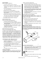
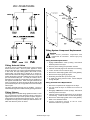
Intake Air Damper/Cool Down Damper
Steam model dryers require the use of both an intake air
damper and a cool down damper. During the heat cycle, the
intake air damper is opened to allow fresh air to be drawn
across the steam coils. On the cool down cycle, the inlet air
damper closes and the cool down damper opens. This draws
fresh air into the tumbler (basket) section exhausting all of
the 13,000 cfm (368 cmm) airflow, which insures a fast cool
down of the load. (Refer to the Cool Down Cycle illustration
on page 17.)
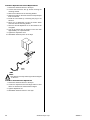
Intake Air Damper Replacement
1. Discontinue electrical service to the dryer.
2. Discontinue the air supply to the dryer.
3. Remove the character panel on the right hand side of
the dryer - the 464 perforated panel - to access the
pneumatic piston of the air intake damper.
4. Remove the two (2) 1/4" poly x 1/4" M.P.T. connectors
from the piston.
5. Remove the C-clip from one end of the 1/2" clevis pin.
6. Remove the 7/16-20 clevis rod from the piston.
7. Remove the piston from the piston support.
8. To install new intake air damper piston, reverse Step #7
through Step #3.
9. Reestablish the air supply to the dryer.
10. Reestablish electrical service to the dryer.
Cool Down Damper Piston
Replacement
1. Discontinue electrical service to the dryer.
2. Discontinue the air supply to the dryer.
3. Remove the two (2) 1/4" poly x 1/4" M.P.T. connectors
from the piston.
4. Loosen the 1/4-20 x 3/8" setscrew from the clevis and
remove the clevis pin.
5. Remove the piston from the damper cylinder mounting
plate.
6. To install new cool down damper piston, reverse Step
#5 through Step #3.
7. Reestablish the air supply to the dryer.
8. Reestablish electrical service to the dryer.
MAN5049

18 American Dryer Corp. 450260-1
Tilting System Component Replacement
Caution
Never service pneumatic components with
compressed air connected. Serious injury may
result.
Tilting Solenoid Replacement
1. Engage EMERGENCY STOP (E-Stop). Discontinue
electrical power to the dryer.
2. Remove panel covering the pneumatic controls.
3. Label the solenoid plugs as an aid when reconnecting.
4. Loosen screws from the solenoid plug.
5. Remove the solenoid plug (take notice of the gaskets).
6. Remove the E-clip by gently prying off.
7. Slide tilting solenoid valve up off of the post.
8. To install new tilting solenoid valve, reverse Step #7
through Step #3.
Tilting Solenoid Valve Replacement
1. Disconnect compressed air supply from the dryer.
2. Tilt, then level the dryer to exhaust as much air as
possible.
3. Disengage EMERGENCY STOP (E-Stop). Discontinue
electrical power to the dryer.
4. Label the solenoid plugs and air lines as an aid when
reconnecting. Loosen screws from the solenoid plug.
5. Remove the solenoid plug (take notice of the gaskets).
Refer to the illustration above.
6. Loosen compression fittings on the air lines.
Disconnect the three (3) air lines.
!
Tilting Solenoid Valve
The dryer uses a 3-position/4-way/5-port, spring centering
double solenoid valve. With no power applied to either
solenoid, the valve is in a spring centered blocked post state.
In this mode, the dryers tilting pistons will remain in their
present state, not being able to exhaust air or receive air.
When the left solenoid is energized with 24 VAC, the pilot air
pushes the shuttle to the right enabling air to flow into the #2
port and exhausts #4 port. On 2-way tilt models, this is
dependent on a supply of external pilot air from the #4 port of
the opposite solenoid valve. When the right solenoid of the
valve is energized, air flows through the #4 port and the #2
port exhausts the pilot air, the right side of the valve is always
internal pilot.
The tilting solenoid valve has two (2) mufflers. The air is
exhausted through these mufflers thereby quieting the airflow.
Tilting Pistons
The tilting piston is a double acting cylinder that has a 5-inch
(12.7 cm) bore and a 14-inch (35.56 cm) stroke. When air is
applied to the bottom port of the cylinder, the piston begins to
extend and air is exhausted through the top port. Then, if air
is applied to the top port, the bottom port will exhaust the air,
which will cause the piston to retract.
Page is loading ...
Page is loading ...
Page is loading ...
Page is loading ...
Page is loading ...
Page is loading ...
Page is loading ...
Page is loading ...
Page is loading ...
Page is loading ...
Page is loading ...
Page is loading ...
Page is loading ...
Page is loading ...
Page is loading ...
Page is loading ...
Page is loading ...
Page is loading ...
Page is loading ...
Page is loading ...
Page is loading ...
Page is loading ...
Page is loading ...
Page is loading ...
Page is loading ...
Page is loading ...
Page is loading ...
Page is loading ...
Page is loading ...
Page is loading ...
Page is loading ...
Page is loading ...
-
 1
1
-
 2
2
-
 3
3
-
 4
4
-
 5
5
-
 6
6
-
 7
7
-
 8
8
-
 9
9
-
 10
10
-
 11
11
-
 12
12
-
 13
13
-
 14
14
-
 15
15
-
 16
16
-
 17
17
-
 18
18
-
 19
19
-
 20
20
-
 21
21
-
 22
22
-
 23
23
-
 24
24
-
 25
25
-
 26
26
-
 27
27
-
 28
28
-
 29
29
-
 30
30
-
 31
31
-
 32
32
-
 33
33
-
 34
34
-
 35
35
-
 36
36
-
 37
37
-
 38
38
-
 39
39
-
 40
40
-
 41
41
-
 42
42
-
 43
43
-
 44
44
-
 45
45
-
 46
46
-
 47
47
-
 48
48
-
 49
49
-
 50
50
-
 51
51
-
 52
52


Ask a question and I''ll find the answer in the document
Finding information in a document is now easier with AI
Related papers
-
American Dryer AD-464 User manual
-
ADC ML-122 User manual
-
American Dryer Corp. AD-120ES User manual
-
-
American Dryer AD-410 User manual
-
-
-
-
-
Other documents
-
Kmart 43116782 User manual
-
American Dryer AD-330 User manual
-
-
Dometic AFM Furnace DSI Board Assembly Installation guide
-
-
-
-
-
American Dryer AD-15 User manual
-
 Dexter Laundry T-80 6-Cycle Express Programming Manual
