Eneo VKC-1327B-IR/W3 Installation And Operating Instructions Manual
- Category
- Security cameras
- Type
- Installation And Operating Instructions Manual
This manual is also suitable for

1
Installations- und Betriebsanleitung
1/3” Tag/Nacht Kamera
VKC-1327B-IR/W3, VKC-1327B/W3
Installation and Operating Instructions
1/3” Day/Night Camera
VKC-1327B-IR/W3, VKC-1327B/W3
Page is loading ...

3
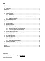
Contents
1. Safety Instructions .............................................................................................................................................26
2. General Description ...........................................................................................................................................
27
2.1 Supplied Items.........................................................................................................................................27
3. Part Names .......................................................................................................................................................
28
4. Installation Instructions ......................................................................................................................................
29
4.1 Power Supply Connections ......................................................................................................................29
4.2 Installation Procedure ..............................................................................................................................29
4.2.1 Installation on Wall......................................................................................................................30
4.2.2 Installation on Ceiling .................................................................................................................30
4.2.3 Assembly on a flush-mounted socket (with the installation kit W3 INST-KIT1, # 88148) ...............31
4.2.4 NOTE - Silicagel bag ...................................................................................................................32
4.3 Setup of the Image Sector .......................................................................................................................32
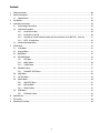
5. SETUP Menu .....................................................................................................................................................
33
5.1 In the Menu .............................................................................................................................................33
5.2 Entering Menu .........................................................................................................................................33
5.3 MAIN Menu..............................................................................................................................................33
5.4 EXPOSURE Menu .....................................................................................................................................34
5.4.1 BLC Menu...................................................................................................................................35
5.4.2 HSBLC Menu ..............................................................................................................................36
5.4.3 D-WDR Menu .............................................................................................................................37
5.5 DAY/NIGHT Menu .....................................................................................................................................37
5.5.1 DAY/NIGHT AUTO Menu...............................................................................................................37
5.6 3DNR Menu .............................................................................................................................................39
5.7 PICTURE Menu.........................................................................................................................................39
5.8 Special Menu...........................................................................................................................................40
5.8.1 CAM TITLE Menu ........................................................................................................................41
5.8.2 MOTION Menu ............................................................................................................................42
5.8.3 PRIVACY Menu ............................................................................................................................43
5.9 LENS Menu..............................................................................................................................................44
5.9.1 FOCUS ADJ. Menu ......................................................................................................................44
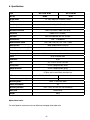
6. Specifications ....................................................................................................................................................45
7. Drilling Plan .......................................................................................................................................................
46
8. Dimensional Drawings .......................................................................................................................................
46
Page is loading ...
Page is loading ...
Page is loading ...
Page is loading ...
Page is loading ...
Page is loading ...
Page is loading ...
Page is loading ...
Page is loading ...
Page is loading ...
Page is loading ...
Page is loading ...
Page is loading ...
Page is loading ...
Page is loading ...
Page is loading ...
Page is loading ...
Page is loading ...
Page is loading ...
Page is loading ...
Page is loading ...
Page is loading ...

26
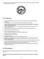
1. Safety Instructions
• Read these safety instructions and the operation manual first before you install and commission the camera.
• Keep the manual in a safe place for later reference.
• Protect your camera from contamination with water and humidity to prevent it from permanent damage.
Never switch the camera on when it gets wet. Have it checked at an authorized service center in this case.
• Never operate the camera outside of the specifications as this may prevent the camera functioning.
• Do not operate the cameras beyond their specified temperature, humidity or power ratings.
Operate the camera only at a temperature range of -20°C to +50°C and at a humidity of max. 85%.
• To disconnect the power cord of the unit, pull it out by the plug. Never pull the cord itself.
• Pay attention when laying the connection cable and observe that the cable is not subject to heavy loads, kinks, or
damage and no moisture can get in.
• The warranty becomes void if repairs are undertaken by unauthorized persons. Do not open the camera housing.
• Never point the camera towards the sun with the aperture open. This can destroy the sensor.
• Installation, maintenance and repair have to be carried out only by authorized service centers.
Before opening the cover disconnect the unit from mains input.
• The fitter is responsible for the system of protection being followed in accordance with the technical data, e.g. by
sealing of the cable outlet with silicone.
• Contact your local dealer in case of malfunction.
• Only use original parts and original accessories from Videor E. Hartig GmbH.
• Do not use strong or abrasive detergents when cleaning the dome. Use a dry cloth to clean the dome surface.
In case the dirt is hard to remove, use a mild detergent and wipe gently.
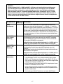
• It is unavoidable that, during manufacturing and also during subsequent use, the moisture contained in ambient air
is, to some extent, present in the housing. With strong temperature variations, the moisture may develop
condensation within the housing.
In order to avoid this in the tightly locked housing, the manufacturer has inserted silica gel bags inside the camera.
It is a physical fact that these silica gel bags do reach saturation after a while. They must therefore be replaced
with new silica gel bags.
• During assembly, care must be taken to ensure that existing seals are correctly inserted and are not
displaced as a result of assembly.
You must not continue to use damaged seals.
NOTE: This is a class A digital device. This digital device can cause harmful interference in a residential area;
in this case the user may be required to take appropriate corrective action at his/her own expense.
ATTENTION: The fastening screws (10) may be completely tightened only then if the accurate position
of the camera is adjusted. If the camera housing on the mount bracket is moved, after the fixing
screws are firm, leakage in the housing can develop.

27
2. General Description
• Weatherproof camera with swivel head bracket
• Sensitivity of 0.2Lux at F1,2 (colour)
• Powerful digital noise reduction (3D-DNR)
• Digital wide dynamic range (D-WDR)
• Removable IR cut filter (IRCF)
• Sensitivity enhancement up to 128x (DSS function)
• Highlight suppress backlight compensation (HSBLC)
• On-screen display (OSD)
• 32x Zoom
• Privacy Masking
• Motion detection
• IR corrected lens with „No-focus-shift”
• Power supply: 12VDC or 24VAC
2.1 Supplied Items
• Camera
• „Easy-Installation” adapter cable
• Service cable
• Heat shrink tube
• Allen key 3mm
• Kit for mounting
• Installation and Operating Instructions

28
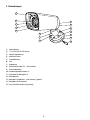
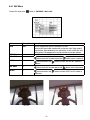
3. Part Names
(1) Housing body
(2) 17 IR LEDs (IR LED version)
(3) Lens hood
(4) Lexan window
(5) Front cover
(6) Neck
(7) Ball housing
(8) Rear cover screws, 2x (not visible)
(9) Rear cover
(10) Neck fastening screws, 3x
(11) Screws for installation kit, 3x
(12) Mount base
(13) Base plate assembly kit – (not visible), (optional)
(14) Panel assembly kit (optional)
(15) Easy-Installation cable (camera side)
1
2
3
4
5
6
7
8
9
10
12
13
14
11
15

29
4. Installation Instructions
• Make sure the power is removed before installation.
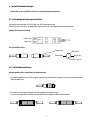
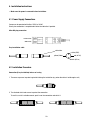
4.1 Power Supply Connections
Camera can be operated with either 12VDC or 24VAC.
Polarity free connection is acceptable but follow the indication if possible.
AC or DC plug connection
12VDC/24VAC
GND/24VAC
Easy Installation cable
4.2 Installation Procedure
Connection (Easy installation) in base of casing
1. The cover cap serves to protect against dirt during the installation (e.g. when the cable is led through a wall).
2. The attached shrink tube serves to protect the connection.
To use this, cut off a suitable amount, push it over the connection and shrink it.
red (AC-Hi)
yellow (Video)
black (AC-Lo)
white (GND)
cable side:

30
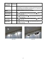
4.2.1 Installation on Wall
1) Loosen three neck fastening screws (10) a little (but not completely) so that camera body can move.
2) Secure the mount base (12) with screws supplied to the wall or ceiling.
Make sure that the cable is routed safely not to be damaged by the mount base (12) (see gap).
3) Separate the housing body (1) by loosening two rear cover screws (8) and place it at a safe area.
4) Set the camera direction roughly and fasten three neck fastening screws (10).
5) Apply the power to the camera.
6) Set the zoom and focus (s. 4.3).
After setting zoom and focus, secure the both knobs.
7) Adjust the parameters in the menu.
8) Remove the power again.
9) Repeat step 1).
This step is a preparation for an easy assembling for step 10).
10) Replace the existing silica-gel bag with new one after setting camera control parameters.
11) Assemble the housing body (1) to the rear cover by tighten two rear cover screws (8).
When securing two rear cover screws (8), do not complete one at a time and another next.
Both screws are recommended to be tightened evenly a little at a time in turn.
12) Trim the camera before the final secure and completely tighten three neck fastening screws (10).
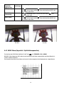
4.2.2 Installation on Ceiling
The camera is now upside down, i.e. the module and housing must be turned 180°.
The modification for upside down mounting must be carried out from the service department of
Videor E. Hartig GmbH.
3. If the camera is mounted with the bottom of its casing directly on a surface, the connection can be stowed in the
base, as shown in the diagram.

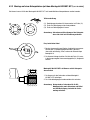
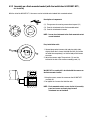
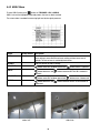
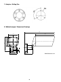
31
Description of components
(11) Fixing screws for securing camera base to panel (13)
(13) Panel for attachment to the flush-mounted socket
(14) Panel for attachment of camera
NOTE:
Screws for attachment to the flush-mounted socket
are not included.
Easy-Installation cable
1. Connect plug socket (camera side) and plug (cable side),
slightly loosen the 3 screws that hold the neck (10) (but do
not undo them completely!), so that the body of the camera
can move.
2. Adjust the camera angle. The panel nut (13) must be
inserted in the hole in the camera assembly panel (14).
13 14
11
W3 INST-KIT1 assembly kit is installed with the camera on
the flush-mounted socket.
1. Using the screws, secure the camera on the W3 INST-KIT1
assembly kit.
2. Re-tighten the 3 screws that hold the neck.
NOTE: Flush-mounted socket, screws for the kit assembly
panel and screws and rawl plugs for wall
attachment are not included.
4.2.3 Assembly on a flush-mounted socket (with the installation kit W3 INST-KIT1,
Art. No. 88148)
With the aid of the W3 INST-KIT1, the camera can be installed onto standard flush-mounted sockets.
Wall
Flush-mounted
socket

32
4.2.4 NOTE - Silicagel bag
As it is not always possible to avoid a situation where a certain amount of moisture remains in the opened casing, we
recommend using the enclosed bag of silicagel in such cases. It must be ensured that the gel is used appropriately,
i.e. opening the protective film too soon can lead to the silicagel becoming saturated in a very short period of time,
thereby making it ineffective.
1. Before inserting the silicagel pack, please remove the aluminium protective sleeve around the pack, as the
silica gel is only effective without the aluminum protective sleeve.
2. Insert the pack between the back of the casing and the camera holder.
3. The silica gel retains the residual moisture that accumulated in the casing during assembly in a moist climate.
4.3 Setup of the Image Sector
• Pull off the camera housing.
• Power up the camera and connect a monitor.
• Loosen Zoom adjustment knob and adjust the zoom setting.
• Loosen Focus is adjustment knob and adjust the focus.
• Tighten both locking screws when adjustment is done. Close the housing.
NOTE: For a precise adjustment of cameras installed outside it is recommended to place a ND (Neutral
Density) filter in front of the lens while settings are done. This opens up the iris and allows a setting
which is constant at changing light conditions due to the narrower depth of field.

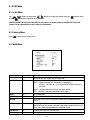
33
5. SETUP Menu
5.1 In the Menu
Use , buttons to move menu, , buttons to change the settings and press button to select
or enter. button stands for MENU or ENTER button.
FACTORY DEFAULT in this manual may NOT be the same as the default values by FACTORY SET due to the
changes for the improvements or the customers requirements.
5.2 Entering Menu
Press button on the back of camera.
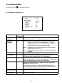
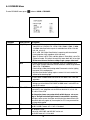
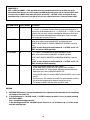
5.3 MAIN Menu
MAIN Factory Default Descriptions
EXPOSURE –
Sets SHUTTER, AGC, SENSE-UP, BLC and D-WDR.
DAY/NIGHT AUTO
Sets DAY / NIGHT to AUTO, NIGHT and DAY
AUTO – Camera switches DAY from/to NIGHT automatically.
DELAY, D –>N LEVEL, N –>D LEVEL and NIGHT MODE can be set in
the menu.
NIGHT – Forced to remove IR cut filter and switch to B/W
DAY – DAY/NIGHT is disabled and outputs colour video
3DNR ON
Sets 3DNR LEVEL
PICTURE –
Sets SHARPNESS, BLUE, RED, GAMMA and WHITE BAL
SPECIAL –
Sets CAM TITLE, D-EFFECT, MOTION, PRIVACY, SYNC, LANGUAGE and OSD
COLOR.
LENS DC
Selects DC or MANUAL lens.
BRIGHTNESS for both lenses can be set in the menu. Provides FOCUS ADJ. to
assist easy and sharp adjustments for ZOOM and FOCUS.
FACTORY SET NO
Restores and saves FACTORY DEFAULTS
EXIT –
Save and exit

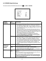
34
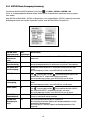
5.4 EXPOSURE Menu
To enter EXPOSURE menu, press button at MAIN > EXPOSURE.
EXPOSURE Factory Default Descriptions
SHUTTER 1/60 (1/50)
1) If LENS at MAIN menu was set to DC, a fixed shutter is selectable from
1/60 (NTSC) or 1/50 (PAL), FLK, 1/250, 1/500, 1/2000, 1/5000, 1/10000,
1/100000 and a fixed sense-up rate is selectable from x256, x128, x64,
x32, x16, x8, x4, x2.
At x2~x256, DSS (Digital Slow Shutter) is operating with the selected
frame integration rates regardless of the light level.
When TV system is NTSC (PAL) and Main power is 50Hz (60Hz), set to FLK
(Flickerless mode). FLK makes the sensitivity lower about 30% at low light.
DC lens must be used for these settings to get a proper video level.
AUTO
2) If LENS at MAIN menu was set to MANUAL, SHUTTER should be set to
AUTO to get a proper video level with the automatic shutter range between
1/60 (1/50)~1/100,000sec.
Colour rolling or Video level hunting under Fluorescent or similar lighting
may occur in this configuration.
Any other fixed shutter settings require a manual iris lens to control the
amount of the incoming light.
AGC –
1) If DAY / NIGHT at MAIN menu was set to AUTO or NIGHT, AGC is not user
adjustable.
Middle
2) AGC can be set to MIDDLE, HIGH, OFF or LOW.
Settings are not available if DAY /NIGHT at MAIN menu is set to AUTO for
non-IR LED version.
SENSE-UP OFF or AUTO
SENSE-UP is available only when SHUTTER is 1/60 (1/50) or AUTO.
If set to AUTO, max. integration rate for DSS can be set to x2, x4, x8, x16,
x32, x64, x128 or x256.
The integration frames vary automatically within the max. rate accor-
ding to the light level when light becomes low and DSS is operating.
The higher sense-up rate, the higher sensitivity but the slower refresh rate.
Some white dots may appear by sense-up due to CCD’s long accumulation
by a long shutter period.
BLC OFF
OFF, BLC and HSBLC are available.
See BLC & HSBLC menus at 5.4.1 & 5.4.2 for detail.
D-WDR OFF
OFF disables D-WDR.
If set to ON, LOW COMP. and HIGH SUP. can be set.
See D-WDR menu at 5.4.3 for detail.

35
5.4.1 BLC Menu
To enter BLC menu, press button at EXPOSURE > BLC > BLC.
BLC Factory Default Descriptions
GAIN LOW
Sets the compensation gain to LOW, MIDDLE or HIGH.
Setting to HIGH gets higher compensation for the back light. To get the best
compensation, adjust window for size and location as well as GAIN. BLC may
not be perfect if the background is varying continuously in bright and dark.
DEFAULT –
Loads the default for BLC settings.
HOR. MOVE 2
button moves BLC window leftward and button moves it rightward
WIDTH 4
button decreases and button increases WIDTH of BLC window at
rightmost.
VER. MOVE 4
button moves BLC window upward and button moves it downward.
HEIGHT 3
button decreases and button increases HEIGHT of BLC window at
bottommost.
BLC OFF BLC ON

36
5.4.2 HSBLC Menu
To enter HSBLC menu, press button at EXPOSURE > BLC > HSBLC.
HSBLC cuts out the highlighted video and process that area as black masked.
The cut out video is excluded in measuring light level by the signal processor.
HSBLC Factory Default Descriptions
LEVEL 8
Sets the threshold for highlight cut out between 0~8.
Lower setting is more sensitive and starts cutting out from lower level of
highlight. The cut out area is masked by black colour.
DEFAULT –
Loads the default for HSBLC settings.
HOR. MOVE 1
button moves BLC window leftward and button moves it rightward
WIDTH 6
button decreases and button increases WIDTH of BLC window at
rightmost.
VER. MOVE 2
button moves BLC window upward and button moves it downward.
HEIGHT 4
button decreases and button increases HEIGHT of BLC window at
bottommost.
HSBLC OFF HSBLC ON

37
5.4.3 D-WDR Menu
To enter D-WDR menu, press button at EXPOSURE > D-WDR > ON.
D-WDR enhances the dynamic range of video by means of digital compensation for the dark and highlight areas.
D-WDR Factory Default Descriptions
LOW COMP. 10
LOW COMP. is a compensation gain for the dark level (area).
Higher value gets higher compensation.
Noise is also increased by the compensation.
HIGH SUP. 95
HIGH SUP. is a suppression gain for the highlight level (area).
Higher value gets higher suppression.
DEFAULT –
Loads the default for D-WDR
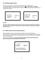
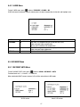
5.5 DAY/NIGHT Menu
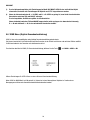
5.5.1 DAY/NIGHT AUTO Menu
To enter DAY/NIGHT AUTO menu, press button at MAIN > DAY/NIGHT > AUTO.
Threshold levels for D –> N and N –> D can be set.
When switched to NIGHT, camera removes its IR cut filter and switches to B/W mode.
IR LED version Non-IR LED version

38
DAY NIGHT AUTO Factory Default Descriptions
DELAY 5
DELAY is the duration which should maintain its status before making the
D –> N or N –> D switches. Camera checks the light level seamlessly if it
crosses over the threshold levels of D –> N LEVEL or N –> D LEVEL. To make
switching, the state must maintain unchanged for longer than DELAY time.
DELAY can avoid the unwanted/frivolous switching by a short term lights
such like the light from the passing car.
D –> N LEVEL 35
D –> N LEVEL is a threshold level to switch from DAY to NIGHT.
Higher value makes camera entered NIGHT at brighter light level.
TO ENTER NIGHT MODE AT LOWER ILLUMINATION, DECREASE it and vice
versa.
Try NOT to make the gap too small between D –> N LEVEL and N –> D
LEVEL to avoid the switch repeating.
N –> D LEVEL 85
N –> D LEVEL is a threshold level to switch from NIGHT to DAY.
Higher value makes camera exited NIGHT at brighter light level.
TO EXIT NIGHT MODE AT BRIGHTER ILLUMINATION, INCREASE it and vice
versa.
Try NOT to make the gap too small between D –> N LEVEL and N –> D
LEVEL to avoid the switch repeating.
NIGHT MODE B/W
• If set to B/W, camera outputs B/W video at NIGHT.
In B/W mode, BURST can be set to OFF (default)/ON in DAY/NIGHT
B/W menu. BURST OFF shows sharper and better resolution but some
equipments may have a problem with BURST OFF.
• If set to COLOR, video is in colour at NIGHT when DAY/NIGHT in main menu
is AUTO.
For ICR versions, ICR switches out at NIGHT for both mode but its colour
may be inaccurate because IR spectrum couldn’t be cut out.
The settings for BURST will also affect any NIGHT mode.
IMPORTANT !!!
DAY -> NIGHT and NIGHT -> DAY operations must be examined and verified at the final step of the
installation. Block the lens for a few seconds for NIGHT mode and release and let it return to DAY mode.
If camera stays at NIGHT mode more than 10sec, decrease N –> D LEVEL a little and repeat the fore-
mentioned steps. If the scene is too dim or lens iris was adjusted near close, it may not return to DAY.
CAUTION
1) DAY/NIGHT AUTO menu is strongly recommended to be adjusted for the actual object after completing
all settings of lens and P/T/Z.
2) If the gap between D –> N LEVEL and N –> D-LEVEL becomes too small, it is easy to repeat switching
DAY from/to NIGHT.
Gap is recommended bigger than 45.
If the switching between DAY and NIGHT repeats, decrease D –> N and increase N –> D a little in turn
until the repeating stops.

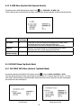
39
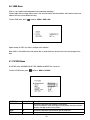
5.6 3DNR Menu
3DNR is a very sophisticated and powerful noise reduction technology.
Camera judges the real image and the noise in the unit of horizontal and vertical blocks and frame by frames and
reduces the noise in three dimensional way.
To enter 3DNR menu, press
button at MAIN > 3DNR > ON.
Higher settings in LEVEL will result in stronger noise reduction.
When 3DNR is ON in MAIN menu, short motion blur or comet effect may be seen for the fast moving target in the
dark.
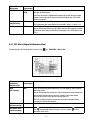
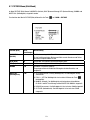
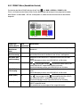
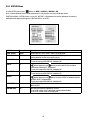
5.7 PICTURE Menu
In PICTURE menu, SHARPNESS, BLUE, RED, GAMMA and WHITE BAL. can be set.
To enter PICTURE menu, press
button at MAIN > PICTURE
PICTURE Factory Default Descriptions
SHARPNESS 13
Increases or decreases the sharpness of the picture.
Too much sharpness make the image harsh and shows more noise and line
flicker at the edge of object in the picture.
BLUE 90
Increases or decreases the blue colour gain of the picture
RED 70
Increases or decreases the red colour gain of the picture

40
PICTURE Factory Default Descriptions
GAMMA 0.45
Adjustable by 0.05.
Lower value increases the gain of the dark area and vice versa.
WHITE BAL ATW
1) ATW (Automatic Tracking White balance): WB is performed automatically.
2) PUSH –> SET: WB is performed only whenever
button is pressed.
3) MANUAL: Adjusts WB with the fixed values of BLUE and RED in
WHITE BAL MANUAL menu.
4) INDOOR: WB is fixed for about 3100K.
5) OUTDOOR: WB is fixed for about 5100K.
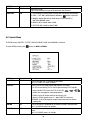
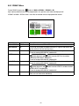
5.8 Special Menu
In SPECIAL menu, CAM TITLE, D-EFFECT, MOTION, PRIVACY, SYNC and LANGUAGE. can be set.
To enter SPECIAL menu, press
button at MAIN > SPECIAL
SPECIAL Factory Default Descriptions
CAM TITLE OFF
If set to ON, CAM TITLE is displayed on the screen.
See „5.8.1 CAM TITLE menu” for detail.
D-EFFECT –
FREEZE: If set to ON, image freezes and show the still image.
FLIP: OFF (normal display), H-FLIP (Left & right mirrored), V-FLIP (upside
down) and H/V FLIP. In case of V-FLIP or H/V-FLIP,
, , ,
buttons are rearranged to match the directions.
D-ZOOM: If set to ON, Digital zoom can be set up to x32.
When D-ZOOM is greater than x1.1, digital PAN/TILT can be set.
NEG.IMAGE: If set to ON, Negative image is output and useful to see the
negative film.
MOTION OFF
If set to ON, motion is displayed on the monitor by means of digital effect.
See „5.8.2 MOTION menu” for settings.
PRIVACY OFF
If set to ON, up to 8 privacy masks are displayed on the monitor by means of
blocks.
See „5.8.3 PRIVACY menu” for settings.

41
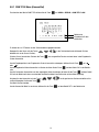
5.8.1 CAM TITLE Menu
To enter CAM TITLE menu, press button at MAIN > SPECIAL > CAM TITLE > ON
Command line
CAM TITLE input line
Up to 15 characters from the character table can be input.
Use
, , , buttons to move cursor (blink character is on the cursor position) in the character table.
Press
button to select and the selected character will be input and displayed on CAM TITLE input line.
To move the input position CAM TITLE input line, press
button on .
To clear CAM TITLE input line, press
button on CLR on command line.
To set the location of CAM TITLE to be displayed on the video, press
button on POS on command line
and then menu disappears and CAM TITLE will be displayed on the video.
Use , , , buttons to locate CAM TITLE at the proper position and press button to fix.
Menu will appear again.
To finish CAM TITLE menu, press
button on RET on command line.
SPECIAL Factory Default Descriptions
SYNC INT
Fixed to INTERNAL synchronization
LANGUAGE ENGLISH
ENGLISH, KOREAN, JAPANESE, CHINESE 1, CHINESE 2 are available.
When changing LANGUAGE, select language and press
button to load
new fonts. It takes about 8 seconds to load new language fonts.
OSD COLOR 3
OSD COLOR can be set to one of 16 colours.

42
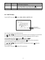
MOTION Factory Default Descriptions
AREA SELECT AREA1
Selects one of 4 areas, AREA1~AREA4, to be adjusted.
AREA DISPLAY ON
If set to ON, the window selected by AREA SELECT appears and enables the
motion detection for that area and vice versa.
HOR. MOVE 12
Moves the window selected by AREA SELECT leftward or rightward.
To see the moving, AREA DISPLAY should be ON.
WIDTH 32
button decreases and button increases WIDTH of the window
selected by AREA SELECT at rightmost
To see the change, AREA DISPLAY should be ON.
VER. MOVE 7
Moves the window selected by AREA SELECT upward or downward.
To see the moving, AREA DISPLAY should be ON.
HEIGHT 24
button decreases and button increases HEIGHT of window selected
by AREA SELECT at bottommost
To see the change, AREA DISPLAY should be ON.
SENSITIVITY 40
SENSITIVITY is adjustable between 0 and 40 for the window selected by
AREA SELECT.
MOTION VIEW OFF
MOTION VIEW setting is applied for all areas.
If set to ON, motion result is displayed as green coloured video.
If set to OFF, motion result is not displayed.
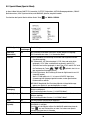
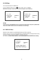
5.8.2 MOTION Menu
To enter MOTION menu, press button at MAIN > SPECIAL > MOTION > ON.
Up to 4 motion detection areas can be programmed in size, position, sensitivity and display on/off.
If MOTION in MAIN > SPECIAL menu is set to ON, „MOTION” is displayed on the monitor whenever the motion is
detected and the digital effect appears if MOTION VIEW is set to ON.

43
PRIVACY Factory Default Descriptions
AREA SELECT AREA1
Selects one of 8 areas, AREA1~AREA8, to be adjusted.
AREA DISPLAY ON
If set to ON, the window selected by AREA SELECT appears and enables the
privacy mask for that area and vice versa.
HOR. MOVE 8
Moves the window selected by AREA SELECT leftward or rightward.
To see the moving, AREA DISPLAY should be ON.
WIDTH 16
button decreases and button increases WIDTH of the window
selected by AREA SELECT at rightmost
To see the change, AREA DISPLAY should be ON.
VER. MOVE 12
Moves the window selected by AREA SELECT upward or downward.
To see the moving, AREA DISPLAY should be ON.
HEIGHT 16
button decreases and button increases HEIGHT of window selected
by AREA SELECT at bottommost
To see the change, AREA DISPLAY should be ON.
COLOR 0
Sets one of 16 colours for the mask window selected by AREA SELECT.
Each area can select colour individually.
5.8.3 PRIVACY Menu
To enter PRIVACY menu, press button at MAIN > SPECIAL > PRIVACY > ON.
Up to 8 privacy detection areas can be programmed in size, position, mask colour and display on/off.
If PRIVACY in MAIN > SPECIAL menu is set to ON, the masked areas are displayed on the monitor.
Page is loading ...
Page is loading ...
Page is loading ...
Page is loading ...
Page is loading ...
-
 1
1
-
 2
2
-
 3
3
-
 4
4
-
 5
5
-
 6
6
-
 7
7
-
 8
8
-
 9
9
-
 10
10
-
 11
11
-
 12
12
-
 13
13
-
 14
14
-
 15
15
-
 16
16
-
 17
17
-
 18
18
-
 19
19
-
 20
20
-
 21
21
-
 22
22
-
 23
23
-
 24
24
-
 25
25
-
 26
26
-
 27
27
-
 28
28
-
 29
29
-
 30
30
-
 31
31
-
 32
32
-
 33
33
-
 34
34
-
 35
35
-
 36
36
-
 37
37
-
 38
38
-
 39
39
-
 40
40
-
 41
41
-
 42
42
-
 43
43
-
 44
44
-
 45
45
-
 46
46
-
 47
47
-
 48
48


Eneo VKC-1327B-IR/W3 Installation And Operating Instructions Manual
- Category
- Security cameras
- Type
- Installation And Operating Instructions Manual
- This manual is also suitable for
Ask a question and I''ll find the answer in the document
Finding information in a document is now easier with AI
in other languages
- Deutsch: Eneo VKC-1327B-IR/W3
Related papers
-
Eneo HDB-2000MIR1080 Installation And Operating Instructions Manual
-
-
-
-
-
-
-
-
-
